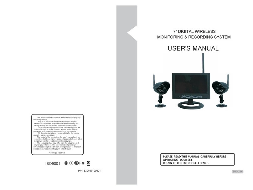
Sensocon Siren Air Flow Alarm User manual

1
www.sensocon.com
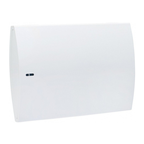
The SiREn™ is an air flow monitor that provides visual and audible indications for air flow status. During
normal operating conditions the SiREn™ will show green LED bars indicating a safe condition. If the air
flow drops below the set point, the SiREn™ LED bars will flash red and give an audible alarm until the
air flow returns to an acceptable condition or the silence button is pushed. The SiREn™ also has a
relay output, and night set back option.
Duct Mount Probe Installation
1. Drill a 5/8” (16mm) hole into the air duct at a minimum of 12”(30mm) above the exhaust and
12”(30mm) below any bends in the duct.
2. Determine the probe insertion depth (approx. center of exhaust duct) and tighten the probe gland
base (A) to that depth.
3. Insert the probe at an angle so that the duct is seated between the lip (B) and the fastener (C) of
the probe gland.
4. Ensuring that the opening of the probe is facing the direction of the air flow, rotate the probe the
rest of the way into the duct.
5. Tighten the probe to the duct by turning the fastener (C) counter-clockwise.
Operating Temperature: 60 - 100°F (16 - 37°C)
Velocity Range: 40 - 2000 fpm (0.2 - 10.2 mps)
Power: 12 - 24 VDC
Input Current: 0.5 A Max
Repeatability: 2%
Relay input: Night Set Back
Relay output: SPDT 2A @ 30 VDC
Audible Alarm: 87 dB
Probe Cable Length: 12ft (3.6m)
Power Adapter Cable Length: 6ft (1.8m)
Optional
Power Adapter Extension Cable: 6ft (1.8m)
Specifications Dimensions
3.14”
(79.8mm)
1.09”
(27.8mm)
2.45”
(62.2mm)
3.14”
(79.8mm)
2.73”
(69.4mm)
2.73”
(69.4mm)
0.37”
(9.4mm)
Duct Mount Probe
5.56” (141.2mm)
1.38”
(35.1mm)
Mounting Bracket
Bulletin 114-0
C
B
A
12”
12“

2
www.sensocon.com
TOP
Calibration Button
BOTTOM
Siren™ Installation
1. Select desired Dip Switch configuration (see Dip Switch Configuration).
2. Mount the unit either using the interlocking strips or the mounting bracket (See Mounting Options).
Be sure to place the unit in an easily visible and reachable location.
3. Connect the power adapter and sensor probe via the ports located underneath the unit. The groove
located on the back of the unit provides room for the cables to run behind the alarm.
4. Plug in the wall adapter and proceed to Calibration.
5. See the 6-Position Terminal below for hooking up the unit using a power source other than the wall
adapter, relay output, and night setback input.
Wall Adapter
Sensor Probe
Connection
FRONT
Dip Switch Configuration
• Dip 1- For calibration of set point- (ON)set point is at 80% of velocity at set-up, (OFF)calibrates the
set point to current velocity.
• Dip 2- (ON)alarm will auto reset when proper velocity is achieved; (OFF)alarm condition latches
(requires special reset).
• Dip 3- (ON)audible alarm will silence when button is pressed, but will sound again after 120
seconds; (OFF)audible alarm is permanently silenced when the silence button is pressed.
Dip Switch 123
On
OFF
Alarm point is
set at 80% of
velocity at
set-up
Alarm point is
set at the
velocity at
set-up
Alarm will automatically
reset when velocity
returns to an acceptable
range
Alarm will latch and
requires a 3 second
hold of the silence
button to reset Relay
and Red LED. Audible
alarm will automatically
reset.
When audible alarm
sounds and the mute
button is pushed, the
audible alarm will sound
again in 120 seconds if
the velocity remains in an
alarm condition.
When audible alarm
sounds, the mute button
will permanently silence
the audible alarm.
Alarm
Set Point Alarm Reset Alarm Silence
Use
ON
l2 3
ON
l2 3
Dip Switch
BACK
VIEW
1. Normally Open
2. Common
3. Normally Closed
4. Night Set Back
5. 24 VDC
6. Ground*
* ground is shared by power & Night Set Back
6-Position Terminal

www.sensocon.com
Calibration w/Dip Switch 1 on (Recommended)
1. Run the cabinet so that it achieves its normal operational air velocity.
2. Once the cabinet reaches operational air velocity, locate and hold down the calibration button found
on top of the unit.
3. The unit will indicate calibration in progress with purple blinking LED bars.
4. Once the unit has successfully calibrated, a green light will flash 3 times.
5. If the calibration is unsuccessful, a red light will flash 3 times, possibly indicating turbulent flow.
Calibration w/Dip Switch 1 off
1. Run the cabinet at the desired minimum flow rate.
2. Once the cabinet reaches the desired minimum flow rate, locate and hold the calibration button
found on top of the unit.
3. The unit will indicate calibration in progress with purple blinking LED bars.
4. Once the unit has successfully calibrated, a green light will flash 3 times.
5. If the calibration is unsuccessful, a red light will flash 3 times, possibly indicating turbulent flow.
6. Once the calibration is completed, return the cabinet to operational air velocity.
7. The unit will now alarm once the air velocity falls below the set minimum flow rate.
Light Color Configuration
Calibration in progress
Slowly Flashing
Slowly Flashing
Solid
Unit has not been calibrated
Night set back mode
Blue
Flashes 3 times Calibration is complete
Solid Operational velocity is above set point
Green
Flashes 3 times Calibration was not successful
Continuously flashing Velocity has dropped below set point
Red
Slowly Flashing
Solid Start Up
Sensor Fault
Yellow
Night Set Back
The night set back option is used to disable the alarm while the cabinet is not in use. The alarm will
illuminate blue while in night set back mode. To initiate night set back, provide a closure of pin 4 and 6
The alarm will go back into normal operation after the closure is removed.
Purple
3

4
www.sensocon.com
LIMITED WARRANTY
SENSOCON warrants its products to be free from defects in materials and workmanship for a period of
one (1) year from the date of shipment, subject to the following terms and conditions: Without charge,
SENSOCON will repair, replace, or refund the purchase price at SENSOCON’s option products found to
be defective in materials or workmanship within the warranty period; provided that:
i. the product has not been subjected to abuse, neglect, accident, incorrect wiring not our own, improp-
er installation or servicing, or use in violation of labels or instructions provided by SENSOCON;
ii. the product has not been repaired or altered by anyone except SENSOCON;
iii. the maximum ratings label and serial number or date code have not been removed, defaced, or
otherwise changed;
iv. examination discloses, in the judgment of SENSOCON, the defect in materials or workmanship
developed under normal installation, use and service; and
v. SENSOCON is notified in advance of and the product is returned to SENSOCON transportation
prepaid before expiration of the warranty period.
THIS EXPRESS LIMITED WARRANTY IS IN LIEU OF AND EXCLUDES ALL OTHER REPRESENTA-
TIONS MADE BY ADVERTISEMENTS OR BY AGENTS AND ALL OTHER WARRANTIES, BOTH
EXPRESS AND IMPLIED. THERE ARE NO IMPLIED WARRANTIES OF MERCHANTABLILTY OR OF
FITNESS FOR A PARTICULAR PURPOSE FOR GOODS COVERED HEREUNDER.
Mounting Options
1. With hooks facing upwards, use 3/8” hex self-drilling screws provided to mount the bracket to the
preferred location.
2. Place the holes located in the back of the unit over the bracket hooks. The interlocking strips will
not interfere with the mounting, as they fit within the groove of the bracket.
3. Gently pull the unit down onto the hooks until it clicks into place.
Bracket Mounting
Interlocking Strip Mounting
1. Remove the plastic backing of both interlocking strips so that the adhesive sides are exposed. (Do
not detach the interlocking strips)
2. With the interlocking strips still attached to the SiREn™, press the adhesive sides firmly to the
prefered mounting surface.
3. Should the SiREn™ need to be temporarily removed, detach one side of the strips from the other
and later reattach in a similar fashion.
ON
l2 3
ON
l2 3
