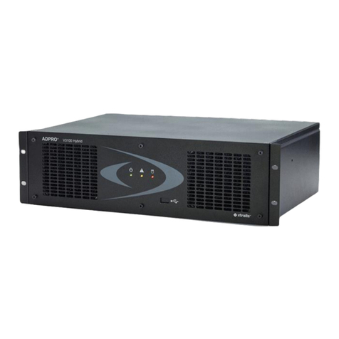
Xtralis ADPRO Presidium User manual

ADPRO Presidium by
Xtralis
(includes Presidium-Mini)
Installation and
User Manual
March 11, 2010
Part 201975.05


ADPRO Presidium by Xtralis Installation and User Manual
Doc. 12384_05 i
Disclaimer
The contents of this document are provided on an "as is" basis. No representation or warranty(either express or implied) is made as to the
completeness, accuracy or reliability of the contents of this document. The manufacturer reserves theright to change designs or
specifications without obligation andwithout further notice. Exceptas otherwise provided, all warranties, express or implied, including
without limitation any implied warranties of merchantability and fitness for a particular purpose are expressly excluded.
Intellectual Property and Copyright
This document includes registered and unregistered trademarks. All trademarks displayed are the trademarks of their respective owners.
Your use of this document does not constitute or create a licence or any other right to use the name and/or trademark and/or label.
This document is subject to copyrightowned by Xtralis AG ("Xtralis"). You agree not to copy, communicate to the public, adapt, distribute,
transfer, sell, modify or publishany contents of this document without the express prior written consent of Xtralis.
General Warning
This product mustonly be installed, configured and used strictly in accordancewith the General Terms and Conditions, UserManual and
product documents available from Xtralis. All proper health and safety precautions must be taken during the installation, commissioning
and maintenance of the product. The system should notbe connected to a power source until all the components have been installed.
Proper safety precautionsmust be taken during tests and maintenance of the products when these are still connected to the power source.
Failure to do so or tampering with the electronicsinside the products can result in an electricshockcausing injury or death and may cause
equipment damage. Xtralis is not responsible and cannot be held accountable for any liability that may arisedue to improper use of the
equipment and/or failure to take proper precautions.Only persons trained through an Xtralis accredited training course can install, test and
maintain the system.
Liability
You agree to install,configure and use the products strictly inaccordance withthe User Manual and product documents available from
Xtralis.
Xtralis is not liable to you or any other person forincidental, indirect, or consequential loss, expense or damages of any kind including
without limitation,loss of business, loss of profits or loss of data arising out of your use of the products. Without limiting this general
disclaimerthe following specific warnings and disclaimers also apply:
Fitness for Purpose
You agree that you have been provided with a reasonable opportunity to appraise the products and have made your own independent
assessment of the fitness or suitability of theproducts for your purpose. You acknowledge that you have not relied on any oral or written
information,representation or advice given by oron behalf of Xtralis or its representatives.
Total Liability
Tothe fullest extent permitted by law that any limitation or exclusion cannot apply,the total liability of Xtralis in relation to the products is
limited to:
(i) in the caseof services, the cost of havingthe services supplied again; or
(ii) in the caseof goods, the lowest cost of replacingthe goods,acquiring equivalent goods or having thegoods repaired.
Indemnification
You agree to fully indemnify and hold Xtralis harmlessfor any claim,cost, demand or damage (including legal costs on afull indemnity
basis) incurred or which may be incurred arising from your use of theproducts.
Miscellaneous
If any provision outlined above is found to be invalid or unenforceable by a court of law, such invalidity or unenforceability will not affect the
remainder which will continue in full forceand effect.All rights not expressly granted arereserved.
FCC Compliance Statement
This equipment has been testedandfoundto comply with the limits for a Class B digital device, pursuant to part 15 of the FCC Rules.
These limits are designedto provide reasonable protection against harmful interference in a residential installation. This equipment
generates,uses and can radiate radio frequency energy and, if not installed and used inaccordancewith the instruction, may cause
harmful interference to radio communications. However, there is no guarantee that interference will not occur in a particular installation. If
this equipment does cause harmful interference to radio or television reception, the user isencouraged to try to correct theinterference by
one or more of the following measures; re-orientate or relocate the receiving antenna, increase the separation between the equipmentand
receiver, connect the equipment to a power outlet which is on adifferent power circuit tothe receiver or consult the dealer or an
experienced radio/television technician for help.
Document Conventions
The following typographic conventions are used in this document.
Convention Description
Bold Used to denote: emphasis
Used for names of menus, menu options, toolbarbuttons
Italics Used to denote: references to other parts of this document or other documents. Usedfor the resultof an
action

Installation and User Manual ADPRO Presidium by Xtralis
ii Doc. 12384_05
The following icons are used in this document
Apple m DNSResponder Licence Agreement
Presidium uses Apple mDNSResponder open source software. This softwareis covered bythe Apple Public Source Licence. PApple
mDSNSResponder software is available from Apple website: http://developer.apple.com/opensource/internet/bonjour.html
The ADPRO Product Installation and Upgrade DVD contains a copy of all distribution licences relevant to Presidium.
Tradename statement
Xtralis ADPRO is a registered trademark of Xtralis AG Pty Ltd.
Lightning or Related Voltage Surges
Damage or malfunction caused by lightning or related voltage surges may be excluded from the manufacturer’s warranty at the
manufacturer’sdiscretion.
Safety Procedures
Installations in the United States of America and Canada
For systems installed in the United States of Americaand Canada the following requirement isapplicable:
All equipment installations are required to be in accordance with the National Electrical Code (NEC) ANSI/NFPA 70 and the Canadian
Electrical Code (CEC) Part 1, CAN/CSA C22.1.
Ifthe power cord is not supplied with the Presidiumselect the properpower cord according to your local national electricity code.
USA:use aULlisted type SVT or SJTdetachable powercord.
Canada: use a CSA certified detachable powercord.
Radio Interference
The Presidium complies with Part 15 of the FCC Rules. Operation is subject to the following twoconditions: (1) This device maynot cause
harmful interference, and (2) this device must accept any interference received, including interference that may cause undesired operation.
The Presidium complies with the electromagneticemission limit requirements of AS/NZS CISPR22and EN55022 Class A. In a domestic
environment this product may causeradiointerference in whichcase the user may be required to take adequate measures.
Internal Lithium Battery
Caution: The Presidium contains an internal lithium battery.
There is danger of explosion ifthe battery is incorrectly replaced.
The battery is not user replaceable and can only be replaced by Xtralis or their Authorised Service Representative.
Convention Description
Caution: This icon is used to indicate that there is a danger to equipment. The danger could be loss of data,
physical damage, or permanent corruption ofconfiguration details.
Warning: This icon is used to indicate that there is a danger of electric shock. This may lead todeath or
permanent injury.
Warning: This icon is used to indicate that there is a danger of inhaling dangerous substances. This may
lead to death or permanent injury.
Information: This icon is used to indicate that the particular feature or action is not available whenusingthe
Presidium Mini product.

ADPRO Presidium by Xtralis Installation and User Manual
Doc. 12384_05 iii
Compliance of Power Cord
Caution: If the power cord supplied with the Presidium or the Presidium Mini plug pack is not suitable for your local power
connection,do not modify the cordor plug pack. Please purchase a power cord that has the safety approvals
appropriatefor your country.
Connection to Other Equipment
Caution: All interface ports on thePresidium mustbe onlyconnected tootherequipment or systems that are Safety Extra Low
Voltage (SELV) rated. Failure to do so will invalidate the electrical safety approval and may cause injury or loss of life
Contact Us
The Americas +1 781 7402223 Asia +852 2916 8894 Australia and New Zealand +61 3 9936 7000
Continental Europe +32 56 24 19 51 UK and the Middle East +44 1442 242 330
www.xtralis.com

Installation and User Manual ADPRO Presidium by Xtralis
iv Doc. 12384_05
Declaration of Conformity
Manufacturer's Name: Xtralis AG Pty Ltd
Manufacturer's Address: 4 North Drive,
Virginia Park
236-262 East Boundary Road
Bentleigh East
VIC 3165
Australia.
Authorised EU Representative: Xtralis (UK) Ltd,
Vision House,
Focus 31, Mark Road
Hemel Hempstead
Hertfordshire HP2 7BW, UK
declares, that the product(s):
Product Name: ADPRO Presidiumby Xtralis IntelligentVideo System
Model Number: PDM-xx
VM-15
Product Options: All
Product Name: ADPRO Presidium-Mini Intelligent Video System
Model Number: PDM-Mini
meet the Standards detailed below.
EMC Emissions EN55022:1998 (CISPR 22:1997) + A1, A2, AS/NZS CISPR 22:2006 Class A
Conducted and radiated emissions.
FCC Part 15 Class A Conducted and radiated emissions.
EN 61000-3-2:2000 + A1 + A2 Current harmonic emissions.
EN 61000-3-3:1995 + A1 Voltage fluctuations and flicker.
EMC Immunity EN 50130-4:1995 +A1 + A2 Alarm systems immunity.
Safety EN 60950-1:2001 Safety of Information Technology Equipment
IEC 60950-1:2001 1991 Safety of Information Technology Equipment
Supplementary Information
The products listed comply with the requirements of the Low Voltage Directive 2006/95/EC (where applicable) and the
EMCDirective 2004/108/EC and carries the CE marking accordingly. The products were tested in a typical configuration.
The CE Mark first applied in 2002.

ADPRO Presidium by Xtralis Installation and User Manual
Doc. 12384_05
Contents
1 Introduction ......................................................................................................................................1
1.1 Features of the Presidium ..................................................................................................1
1.2 Unique Features of Presidium Mini ...................................................................................1
1.3 Installation Steps ................................................................................................................2
2 Design Guide ....................................................................................................................................3
2.1 Introduction .........................................................................................................................3
2.1.1 Purpose ....................................................................................................................3
2.1.2 Scope .......................................................................................................................3
2.1.3 Intended Audience ...................................................................................................4
2.1.4 Other Resources ......................................................................................................4
2.2 Quick Guide .........................................................................................................................4
2.3 The Role of Security ...........................................................................................................5
2.3.1 ADPRO Solutions ....................................................................................................5
2.3.2 Presidium - an ADPRO Solution ..............................................................................5
2.4 Presidium System Concept ................................................................................................6
2.4.1 Operational Concept ................................................................................................6
2.4.2 Basic Parameters .....................................................................................................6
2.5 System Design ....................................................................................................................6
2.5.1 Preliminary Information ............................................................................................7
Assess Site Plans ....................................................................................................7
Discuss Requirements .............................................................................................7
Recommendations ...................................................................................................7
2.5.2 Site Survey ...............................................................................................................7
Detailed Site Plan ....................................................................................................8
Site Images ..............................................................................................................8
Clarify Requirements .............................................................................................10
2.5.3 System Hardware ..................................................................................................11
Camera Selection and Location .............................................................................11
Other Detectors Selection and Location ................................................................15
PIR Alignment ........................................................................................................17
PIR Termination .....................................................................................................18
Camera/PIR Alignment ..........................................................................................19
Illumination Requirements .....................................................................................19
Equipment Room ...................................................................................................20
Monitoring Equipment ............................................................................................21
2.6 System Installation ...........................................................................................................22
2.6.1 Camera Installation ................................................................................................22
Alignment ...............................................................................................................22
Installation Hints .....................................................................................................23
Interference Caused by High Voltage or Ground Loops ........................................23
Installation Adjacent to Roads ...............................................................................23
2.6.2 PIR Installation .......................................................................................................23
Alignment ...............................................................................................................23
2.6.3 Instrument Racks and Cablings .............................................................................24
2.7 Site Commissioning ..........................................................................................................25
2.7.1 Presidium Configuration .........................................................................................25
2.7.2 Performance Assessment ......................................................................................25
Detection Tests ......................................................................................................25
Soak Tests .............................................................................................................26
2.7.3 System Tests .........................................................................................................26
2.7.4 Recording System Configuration ...........................................................................26

Installation and User Manual ADPRO Presidium by Xtralis
Doc. 12384_05
2.8 Site Maintenance ...............................................................................................................26
2.8.1 Routine Maintenance .............................................................................................27
2.8.2 Routine Site Maintenance ......................................................................................27
2.8.3 Routine Equipment Maintenance ...........................................................................28
2.8.4 Routine Detection Tests ........................................................................................28
2.8.5 Maintenance to Regulatory Requirements ............................................................28
3 Presidium Connectors ...................................................................................................................29
3.1 Presidium ...........................................................................................................................29
3.2 Presidium Mini .................................................................................................................. 30
3.3 Power Connection ............................................................................................................ 32
3.3.1 Presidium ...............................................................................................................32
3.3.2 Presidium Mini .......................................................................................................32
3.4 Earthing Screw .................................................................................................................. 32
3.5 Video Connections ........................................................................................................... 32
3.5.1 Inputs .....................................................................................................................32
3.5.2 Outputs ..................................................................................................................33
3.6 Alarm Inputs ......................................................................................................................35
3.7 Isolation .............................................................................................................................36
3.8 Alarm Outputs ................................................................................................................... 37
3.9 General I/O Connector ......................................................................................................37
3.9.1 Access/Secure Input ..............................................................................................38
3.9.2 Fault Relay .............................................................................................................39
3.9.3 General Alarm Relay Output ..................................................................................40
3.10 Network Communications ..............................................................................................40
3.10.1 Presidium .............................................................................................................40
3.10.2 Presidium Mini .....................................................................................................40
3.10.3 Network Connector LEDs ....................................................................................40
3.11 Status LEDs .....................................................................................................................41
4 Installation / Configuration ............................................................................................................43
4.1 Unpacking ..........................................................................................................................43
4.2 Install Setup Utility ............................................................................................................43
4.3 Configure the PC Network Connections .........................................................................45
4.4 Configure Presidium ......................................................................................................... 47
4.4.1 Connect to an Presidium .......................................................................................47
Presidium (standard) .............................................................................................48
Presidium Mini .......................................................................................................49
4.4.2 Setup Utility No Activity Timer ...............................................................................50
4.4.3 Using the Setup Utility ...........................................................................................50
4.4.4 System Status ........................................................................................................53
4.4.5 Configure Channels ...............................................................................................54
General Setup ........................................................................................................54
Camera Calibration ................................................................................................56
Areas .....................................................................................................................57
Trigger Area Properties .........................................................................................58
Detection Parameters ............................................................................................60
Alarm Behaviour ....................................................................................................63
Video Monitoring ....................................................................................................65
4.4.6 Network Tab ..........................................................................................................66
Device Name .........................................................................................................66
IP Address Configuration .......................................................................................66
4.4.7 High Level Interface Tab ........................................................................................67

ADPRO Presidium by Xtralis Installation and User Manual
Doc. 12384_05
4.4.8 Security Tab ...........................................................................................................68
Access/Secure Input Type .....................................................................................68
Authentication ........................................................................................................68
Default Settings ......................................................................................................69
4.4.9 Status Tab ..............................................................................................................69
4.5 Saving the Site Records ...................................................................................................69
4.5.1 Saving a Configuration toFile ................................................................................69
4.5.2 Loading a Configuration from File ..........................................................................71
4.5.3 Printing the Site Configuration ...............................................................................71
4.5.4 Upgrading Presidium Software ..............................................................................72
4.6 Troubleshooting ................................................................................................................73
4.6.1 Detection Problems ................................................................................................73
4.6.2 IP Address Forgotten .............................................................................................73
4.6.3 Presidium Will Not Connect ...................................................................................73
Presidium Appears in List of Local Units................................................................73
Presidium Does Not Appear in List of Local Units .................................................74
4.6.4 Password Forgotten ...............................................................................................74
4.6.5 HLI Connection to FastTrace Fails to Operate ......................................................75
4.6.6 Presidium Setup Utility cannot be Started .............................................................75
5 Connection to ADPRO FastTrace / FastTx / FastTrace-R by Xtralis ..........................................77
5.1 Entering the FastTrace / FastTx / FastTrace-R Setup Screen .......................................79
5.2 Presidium Inputs ...............................................................................................................80
5.2.1 Presidium Input Settings ........................................................................................81
Presidium Input Name ...........................................................................................81
Presidium Input Camera View Style .......................................................................81
Camera Behaviour Setup .......................................................................................81
5.3 Advanced Communication Properties ............................................................................82
5.3.1 Presidium High Level Interface Properties .............................................................83
5.4 IP Address Requirements ................................................................................................83
6 Connection to a Third-Party DVR .................................................................................................85
7 Adding a VM15 Module ..................................................................................................................87
8 Specifications .................................................................................................................................89
Appendix A False and Nuisance Alarms .........................................................................................91
Appendix B Site Survey Checklist ...................................................................................................93
Appendix C Example Site Plan ........................................................................................................95
Appendix D System Design and Equipment Checklist ..................................................................97
Appendix E Camera / Lens Selection ..............................................................................................99
Appendix F Commissioning Checklist ..........................................................................................101
Appendix G Site Detection Tests ...................................................................................................103
Appendix H Site Maintenance Tables ............................................................................................105
Appendix I Installation Quick Reference .......................................................................................107
Appendix J Presidium Do’s and Don’ts ........................................................................................109

Installation and User Manual ADPRO Presidium by Xtralis
Doc. 12384_05
List of Figures
Figure 1: Suitable/Unsuitable Perimeter Conditions ..............................................................................9
Figure 2: Suitable/Unsuitable Area Detection Scenes.........................................................................10
Figure 3: Required Video Signal..........................................................................................................11
Figure 4: Camera Dead Zone ..............................................................................................................13
Figure 5: Camera Dead Zone Coverage..............................................................................................13
Figure 6: Recommended Presidium Pole Installation..........................................................................14
Figure 7: Presidium Pole Front View....................................................................................................15
Figure 8: FOV of Curtain PIR with Camera..........................................................................................16
Figure 9: FOV of Wide angle PIR with Camera ...................................................................................16
Figure 10: Camera/PIR Mounting Details ............................................................................................16
Figure 11: Camera/PIR Dead Zone Comparison.................................................................................17
Figure 12: Optimal PIR Angle ..............................................................................................................17
Figure 13: PIR Alignment on Fenceline ...............................................................................................18
Figure 14: Example PIR Barrier...........................................................................................................18
Figure 15: Camera/PIR Alignment.......................................................................................................19
Figure 16: Correctly Illuminated Scenes..............................................................................................20
Figure 17: Typical Connections to a standard Presidium.....................................................................22
Figure 18: PIR Alignment on Fenceline ...............................................................................................24
Figure 19: Rear View of the Presidium................................................................................................29
Figure 20: Cable Entry Requirements.................................................................................................. 30
Figure 21: Rear View of the Presidium Mini enclosure........................................................................30
Figure 22: Typical Connections to a standard Presidium.....................................................................31
Figure 23: Typical Connections to a Presidium Mini............................................................................31
Figure 24: Connection to the VM15 Video Module..............................................................................33
Figure 25: PIR Connections (VM15 shown).........................................................................................35
Figure 26: Alarm and Isolate Input Configuration.................................................................................36
Figure 27: Alarm Outputs.....................................................................................................................37
Figure 28: Pinouts for Presidium General I/O Connector.....................................................................37
Figure 29: Pinouts for Presidium Mini I/O connector............................................................................38
Figure 30: Access/Secure Input Configuration..................................................................................... 39
Figure 31: Installation Screen ..............................................................................................................43
Figure 32: Presidium Setup Utility........................................................................................................44
Figure 33: Presidium Licence Agreement............................................................................................44
Figure 34: Choose Setup Type............................................................................................................45
Figure 35: Local Area Connection Properties......................................................................................46
Figure 36: Internet Protocol Properties................................................................................................46
Figure 37: Establish Connection to the Presidium...............................................................................47
Figure 38: Establish Connection to the Presidium...............................................................................48
Figure 39: Entering IP Address and Port Number................................................................................48
Figure 40: Port Redirection Example...................................................................................................49
Figure 41: Enter Password...................................................................................................................50
Figure 42: Select Function...................................................................................................................51
Figure 43: Change Video Standard......................................................................................................51
Figure 44: Presidium Setup..................................................................................................................52
Figure 45: General Tab........................................................................................................................54
Figure 46: Contrast Level Indicator......................................................................................................55
Figure 47: Camera Calibration.............................................................................................................55
Figure 48: Areas...................................................................................................................................56
Figure 49: Trigger Area Properties.......................................................................................................58
Figure 50: Alarm Logic.........................................................................................................................59
Figure 51: Detection Parameters.........................................................................................................60
Figure 52: Customise Detection Sensitivity..........................................................................................61
Figure 53: Alarm Behaviour .................................................................................................................63
Figure 54: Video Monitoring.................................................................................................................65
Figure 55: Network Tab........................................................................................................................66

ADPRO Presidium by Xtralis Installation and User Manual
Doc. 12384_05
Figure 56: IP Address Configuration....................................................................................................66
Figure 57: Advanced Communication..................................................................................................67
Figure 58: High Level Interface............................................................................................................67
Figure 59: Security Tab........................................................................................................................68
Figure 60: Status Tab...........................................................................................................................69
Figure 61: Presidium Setup Screen .....................................................................................................70
Figure 62: Saveto File.........................................................................................................................70
Figure 63: Load Settings from File.......................................................................................................71
Figure 64: Print Settings.......................................................................................................................71
Figure 65: Software Upgrade option ....................................................................................................72
Figure 66: Enter Password Window.....................................................................................................74
Figure 67: Reset Password..................................................................................................................74
Figure 68: Complete standard Presidium Installation...........................................................................77
Figure 69: Typical Connections to a standard Presidium.....................................................................78
Figure 70: Installer Menu Icon..............................................................................................................79
Figure 71: Typical Video Transmitter User Settings.............................................................................79
Figure 72: Presidium Inputs List...........................................................................................................80
Figure 73: Unallocated Icon .................................................................................................................80
Figure 74: Presidium Input Settings.....................................................................................................81
Figure 75: Mapping the camera inputs.................................................................................................82
Figure 76: FastTrace / FastTx / FastTrace-R Communications...........................................................82
Figure 77: Advanced CommunicationProperties.................................................................................83
Figure 78: Typical Connections to a Third Party DVR..........................................................................85
Figure 79: VM15 Module Installation....................................................................................................87
List of Tables
Table 1: Quick Guide..............................................................................................................................4
Table 2: Video Output Display..............................................................................................................34
Table 3: Fault Relay.............................................................................................................................39
Table 4: Network Connection Indicators ..............................................................................................41
Table 5: Video Motion Thresholds Explanation....................................................................................62
Table 6: Presidium Specifications........................................................................................................89
Table 7: Horizontal FOV - 20 Metres (66 Feet)....................................................................................99
Table 8: Horizontal FOV - 22 Metres (75 Feet)....................................................................................99
Table 9: Horizontal FOV - 25 Metres (83 Feet)....................................................................................99
Table 10: Horizontal FOV - 30 Metres (98 Feet)................................................................................100
Table 11: Camera Maintenance Table...............................................................................................105
Table 12: PIR Maintenance Table......................................................................................................105

Installation and User Manual ADPRO Presidium by Xtralis
Doc. 12384_05

ADPRO Presidium by Xtralis Installation and User Manual
Doc. 12384_05 1
1 Introduction
The Presidium Intelligent Video System is a high performance, modular, multi channel video
movement detection system. It is optimised for maximum protection and reliability in the outdoor
environment.
Presidium Mini is a high performance, DC powered, 2-channel video movement detection
system in a desktop/wallmount enclosure for the protection of smaller properties.
Note: For consistency in this manual, the generic term “Presidium” is used to refer
to both standard Presidium and Presidium Mini.
Important: This symbol is shown next to the section where a feature or procedure
is not applicable to the Presidium Mini.
Presidium employs state of the art digital signal processing hardware and software to provide a
high level of performance by reducing unwanted alarms without compromising detection.
The Presidium has been designed to be fully compatible with all CCIR/PAL and RS170/NTSC
CCTV systems (monochrome and colour). It is simple to include in new designs or to retrofit to
existing CCTV systems to improve security.
1.1 Features of the Presidium
• Modular expansion from 2 to 20 channels per Presidium chassis
• Advanced algorithms to maximise target acquisition and tracking under a wide range of
environmental conditions
• Low probability of false alarms from small animals, clouds, wind and rain
• Multiple free form detection zones
• Additional functionality to enhance the Presidium detection capability and reduce unwanted
alarms to near zero such as directional object detection, dual edge trigger areas used to
qualify alarms, single edge target detection and timer enabled detection for sterile zone
loitering.
• Contrast alarms for sabotage detection
• No video detection for camera, lens or cable failure
• Easy to commission via quick setup feature
• Single cable, High Level Interface to ADPRO FastTrace, ADPRO FastTx and ADPRO
FastTrace-R, reducing wiring and setup time, providing seamless integration (standard
Presidium only)
• External access control input for easy integration into a security system
• External detection inhibit input to reset all alarms
• External alarm inputs for integration of other alarm sensors
• Over temperature alarm (standard Presidium only).
1.2 Unique Features of Presidium Mini
• Two channels
• Small size footprint via desktop/wallmount enclosure
• 12V DC power supply supports battery based operation.

Installation and User Manual ADPRO Presidium by Xtralis
2 Doc. 12384_05
1.3 Installation Steps
The following steps must be followed to install a Presidium system:
• Design the system
- Gather site information (refer to Preliminary Information on page 7)
- Discuss requirements with client
- Survey the site (refer to Site Survey on page 7)
- Select the equipment (refer to System Hardware on page 11)
• Install the system
• Commission the system
- Install Presidium Setup Utility software on PC (refer to Install Setup Utility on page 43)
- Configure the Presidium (refer to Configure Presidium on page 47)
- Assess the system performance (refer to Performance Assessment on page 25)
- Soak test the system (refer to Soak Tests on page 26)
- Perform system tests (refer to System Tests on page 26)

ADPRO Presidium by Xtralis Installation and User Manual
Doc. 12384_05 3
2 Design Guide
2.1 Introduction
The Presidium Intelligent Video System is designed to provide reliable and predictable detection
of intrusion into secure areas. The system analyses images from strategically placed CCTV
cameras to detect 'human-like1’ movement, and if the movement fulfils a number of criteria,
alarms are generated. These alarms can be handled locally or, coupled with ADPRO FastTrace,
ADPRO FastTx and ADPRO FastTrace-R and Monitoring Software, can be transmitted to a
remote central monitoring station, assessed and managed by experienced security personnel. A
well designed, installed and maintained Presidium system can remove the need for onsite
guards or patrols, or provide an adjunct to local monitoring, improving the effectiveness of the
overall site security.
2.1.1 Purpose
The purpose of this Design Guide is to describe the specification, design, installation,
commissioning and maintenance of Xtralis’s ADPRO Presidium Intelligent Video System. The
recommendations presented are designed to achieve optimal system performance and high
reliability.Although there are many variations to the recommended scenarios, any departurefrom
these recommendations may result in less than ideal system performance.
This document describes a typical installation scenario for a medium security Presidium system.
To provide a high security installation, where the intrusion is expected to be covert, detailed
consultation with Xtralis staff is required.
2.1.2 Scope
The following items are addressed in this Design Guide:
• Presidium Operational Background
• Site Survey and System Design
• Equipment Installation
• System Commissioning
• Site and Equipment Maintenance
The following items are not discussed in detail in this guide:
• Design, installation, configuration or maintenance of complementary detection technologies
excepting PIRs supplied by ADPRO (refer to other manufacturer's technical and application
information).
• Installation or configuration of ADPRO FastTrace, ADPRO FastTx or ADPRO FastTrace-R
(refer to the FastTrace / FastTx / FastTrace-R Installation and User Manuals).
• Installation or configuration of Xtralis’s ADPRO VideoCentral Monitoring Software (refer to
Central Monitoring Station Design Guide, Part No: 201700).
• Any relevant Application Notes, Tech Tips and FAQs. Refer to Xtralis website -
www.xtralis.com.
1.Human-like: a feature that is able to differentiate between human and non-human movement for intru-
sion detection.

Installation and User Manual ADPRO Presidium by Xtralis
4 Doc. 12384_05
2.1.3 Intended Audience
The intended audience for this Design Guide includes the following key stakeholders:
• Security Consultants
• System Integrators
• System Installers
• Facilities / Building / Site Managers
2.1.4 Other Resources
A number of other resources should also be used in conjunction with this Design Guide.
• Presidium Design Forms - refer to System Design and Equipment Checklist on page 97.
• Presidium Commissioning Forms - refer to Commissioning Checklist on page 101.
• Presidium Maintenance Forms - refer to Site Maintenance Tables on page 105.
Where Remote Monitoring is a requirement, the Central Monitoring Station Design Guide should
be used in conjunction with this Design Guide.
2.2 Quick Guide
This guide divides the implementation of an Presidium system into four main areas:
• System Design
• System Installation
• Site Commissioning
• Site Maintenance
The Quick Guide shown in Table 1 provides an overview of key design considerations allocated
in each step and may be used as a quick reference. It should be used in conjunction with the
entire Presidium Manual to produce a robust system design.
Table 1: Quick Guide
Area Key Design Considerations Reference
Site Survey & Checklist Conducting a site survey and what
information should be gathered Site Survey on page 7 and Site Survey Checklist on
page 93
Illumination Illumination selection and location for
use with Presidium Illumination Requirements on page 19
Cameras Camera selection and location for
use with Presidium Camera Selection and Location on page 11,
Camera/PIR Alignment on page 19, Camera
Installation on page 22and Camera / Lens Selection
on page 99
PIRs Design and installation of PIRs with
Presidium OtherDetectors Selection and Location on page 15,
PIR Alignment on page 17, Camera/PIR Alignment
on page 19 and PIR Installation on page 23
Presidium Configuration Configuring the Presidium system for
operation Presidium Configuration on page 25
Commissioning and
System Test Testing the system and checking the
detection performance Performance Assessment on page 25, System Tests
on page 26 and Site Detection Tests on page 103
System Maintenance Ensuring the system continually
operates to the required criteria Site Maintenance on page 26, Site Detection Tests
on page 103 and Site Maintenance Tables on
page 105

ADPRO Presidium by Xtralis Installation and User Manual
Doc. 12384_05 5
2.3 The Role of Security
Security is becoming an increasingly accepted part of every day living. It is imperative for
organisations toconsider physical andinformation security as a fundamentally important element
of their overall management strategy. Suitable security must include detailed Risk Analysis and
Management as well as an awareness of Business Continuity Management, ensuring that the
system instituted provides the organisation with the best approach to achieve ongoing success.
The key elements to instituting a security solution are:
• Identify and Evaluate Risks
• Develop Strategy to Remove or Reduce Risks
• Test and Monitor Strategy
2.3.1 ADPRO Solutions
ADPRO provides a range of video security solutions that focus on remote monitoring of facilities,
but also provide excellent onsite monitoring capabilities. The product range features video
transmission, video recording and video detection systems that link to an industry leading
software package, VideoCentral, for remote management and control. A typical approach to
security is to provide an indication when an intrusion has occurred, ADPRO, however,
recognises the value in being able to immediately identify the cause, evaluate the situation and
respond accordingly.
ADPRO's combination of onsite detectors, audio/video recording and transmission to monitoring
stations, provides security in a wide varietyof markets and application areas. Presidium forms an
important element of security solutions where automatic detection and verification of an intrusion
is paramount.
2.3.2 Presidium - an ADPRO Solution
ADPRO Presidium and Presidium Mini, in conjunction with the other Xtralis products, are ideally
suited for security solutions where the risk is illegal intrusion into a high value asset. The
Presidium approach provides reliable protection of a perimeter or sterile area, with rapid
identification of the cause of any intrusion within that perimeter.
The Presidium system, coupled with other ADPRO technologies, can form an important link in
responding to different scenarios:
• A remotely monitored standard Presidium System, linked to a FastTrace or FastTx provides
rapid remote response, with an option for local response follow up. The response from a
remote monitoring station, followed by dispatch of security guards or law enforcement
provides a powerful, flexible and effective solution to many site security problems.
• The presence of a Presidium System at a site can provide rapid local response. When local
notification via standard CCTV monitors is linked to alarm systems for visual and audible
notification at a local monitoring station, it is possible for guards to respond appropriately in
the minimum timeframe. Automatic monitoring of multiple video channels provides
significant security and cost benefits.

Installation and User Manual ADPRO Presidium by Xtralis
6 Doc. 12384_05
2.4 Presidium System Concept
This section provides a brief description of how Presidium performs image processing to
determine if an intruder is present in the protected area.
2.4.1 Operational Concept
Presidium analyses video from CCTV cameras to detect movement that is likely to be an
intruder. A number of criteria, used in conjunction with complex image processing routines, are
used to distinguish between an intruder and some other form of movement. The same
techniques are used to reduce other factors such as changes in contrast from shadows cast by
clouds and moving trees.
Presidium monitors contrast changes and rate of contrast change within the defined detection
areas. This information on contrast changes and rates of change is fed into a number of
computational routines that analyse the changes and extract valid targets from the images whilst
rejecting changes from background movement. The detected targets are further analysed to
ensure that they meet criteria based on size and speed. If the criteria is met, an alarm is
generated.
What is actually considered a target will depend on your particular security requirements. In a
high security environment, the maximum horizontal Field of View (FOV) should be less than for
that in a medium security environment.
2.4.2 Basic Parameters
To achieve high detection probability and effective nuisance alarm rejection, the field of view at
the maximum detection distance should be no more than 16.7 times the target size.
For example, to detect a 1.8m high human target, the recommended maximum field of view at
the maximum detection distance is:
FOV = 16.7 x 1.8m = 30m
If a larger field of view is used, then the detection probability is reduced.
In this scenario, increasing Presidium's sensitivity can only partially compensate for the reduced
detection probability and may lead to an increase in the number of false alarms. It is not
recommended.
The maximum horizontal FOV, and the required target size to be detected determines the
required camera and lens configuration.
2.5 System Design
The system design phase consists of three elements:
•Preliminary Information: Gather general site information and discuss the security
requirements with the customer to ensure that the Presidium meets the customer's
requirements.
•Site Survey: Conduct a site survey to determine site requirements such as the positioning
of cameras and other detectors, lighting, and existing and required communications
infrastructure.
•Equipment Selection: Conduct a comprehensive analysis to determine equipment
requirements, such as camera types and lenses, level and type of illumination, and
communications and control room equipment.

ADPRO Presidium by Xtralis Installation and User Manual
Doc. 12384_05 7
The system design is critical to ensure that the Presidium system performs as expected. A well-
designed system can deliver exceptional performance, whereas a system that has not had a
rigorous design process will not perform to expectations. Presidium provides a high level of
flexibility in its configuration, but is dependent on the quality of video signals and scene content
to deliver a high performance solution.
2.5.1 Preliminary Information
Gather site information to determine Presidium's suitability for the site. If possible, obtain a copy
of the site plans to check the layout and suitability of Presidium.
Assess Site Plans
Assessing the site plans prior to visiting the site allows a quick overview, as knowledge of this is
important for a good Presidium system design. If unable to obtain site plans prior to visiting the
site, then once on site prepare a sketch of the site, remembering to include the immediate
external environment, such as roads and location of neighbouring buildings.
Discuss Requirements
During the preliminary stages, discuss the security requirements and expectations with the
customer's representative. Different areas of the site may have varying security requirements
and knowledge of the external environment is critical in understanding the customer's
requirements and performance expectations from the system. Collect information about the
customer's response requirements, such as use of local guards and/or remote monitoring.
Recommendations
If, after the preliminary investigation phase, the site is deemed suitable for Presidium and the
customer's performance expectations can be met, a site survey should be conducted. The
following criteria determine the site's suitability for a Presidium System:
1. Sterility of protected area, i.e. how well defined is the border surrounding the protected
area, is the area free from general or expected activity, and are there clear areas in which
detection can occur.
2. Customer requirements for response (onsite or remote).
3. Customer expectations of system performance, such as false alarms or integration intothird
party systems.
4. Possible addition of other detection technology, e.g. PIR.
5. At the maximum distance from the camera where a target is expected to be detected, the
horizontal field of view should not exceed 25m, or 20m for high security.
2.5.2 Site Survey
Once preliminary information is collected and the site considered suitable for protection with
Presidium, a site survey can be conducted. Conduct the site survey taking into account any
customer tender or requirements documents to ensure that the survey and subsequent design
meet the customer's specifications and requirements. The site survey draws on the preliminary
information to design a complete system. Determine all necessary criteria for the system and
ensure all relevant information is collected. Where clarification is required, ensure that this is
received from the customer (or their representative). Appendix B contains a checklist for a Site
Survey.
The items required to performa detailed site survey include (1) Digital Camera (2) Tape measure
(3) Workbook, and (4) Site Plans (accurate engineering drawings of the site).
The different stages of a site survey are described below.

Installation and User Manual ADPRO Presidium by Xtralis
8 Doc. 12384_05
Detailed Site Plan
The production of a detailed site plan annotated with key information (refer to Appendix C for an
example) is the key element in completing a successful site survey. As a minimum, the following
information must be included:
1. Location and type of existing illumination, including coverage, to determine its suitability. If
necessary specify additional illumination.
2. The location for the installation of the Presidium system, to confirm cable run lengths for
cameras.
3. If remote monitoring is to be used, confirm the location and type of any existing
communications infrastructure.
4. Location of trees, and other vegetation that may affect detection performance, camera
positioning and field of view.
5. Type and height of fences or barriers to check where intrusion is likely to occur. Also
determine if any concealment of intruders may occur, and what is visible through fences.
6. Any other permanent or semi-permanent structures not already marked on the site plan,
e.g. semi-permanent location of large cable drums, which may obscure camera views.
7. Location of any nearby roads, to determine whether street lighting or car lights from any
roads nearby may present a lighting problem.
8. Location and description of nearby buildings or structures to understand whether lighting
may spill from adjacent properties, or shadows from industrial equipment may affect
performance, e.g. a shadow from a moving crane cast across the FOV of a camera may
cause nuisance alarms.
9. Location of any existing CCTV cameras or other detectors and their suitability with the
Presidium system, or incorporation as a third party detector.
10. Special requirements within protected areas, i.e. high security critical areas within the site,
or special requirements due to dangerous chemicals and/or service reliability.
11. If audio is considered for offsite response, identify the location of any noisy equipment, e.g.
generators, to ensure that any microphones to be installed will not be affected by the noise.
This also relates to onsite audio broadcast equipment, i.e. speakers and horns should be
appropriately located and specified with appropriate power.
Site Images
Collect a detailed set of site images covering all protected areas. The site images provide a
visual reminder when assessing the site plan offsite.These also provide a reference point during
installation and commissioning. Ideally the digital images should be taken under a variety of
lighting conditions, i.e. dawn, daylight, dusk and night. The most challenging lighting conditions
for CCTV systems can occur at dawn and/or dusk. It is vitally important to be aware of the
variable lighting conditions under different circumstances and in different seasons.
The detailed site survey must consider the likely occurrence of seasonal variations. Shedding or
sprouting of new leaves on nearby trees may affect lighting conditions and camera views. Ideally
there should be no trees in any camera views, however this is not always possible. Lighting and
views change as foliage grows or drops, affecting nuisance alarm rates or detection probability.
The following images illustrate some suitable and unsuitable perimeter and area protection
scenarios for a Presidium system.
This manual suits for next models
1
Table of contents
Other Xtralis Security System manuals