Sensorex TX105 User manual

TX105 PH/ORP Transmitter
User Manual
REV B.15T
Sensorex Corporation
11751 Markon Drive
Garden Grove, CA. 92481
www.sensorex.com

2
IMPORTANT SAFETY INFORMATION
Please read and observe the following:
Remove line power before wiring transmitter connections.
Wiring or repairs should only be performed by qualified personnel and only to an
unpowered transmitter.
Whenever it appears that Transmitter safety is questionable, disable the transmitter to
ensure against any unintended operation. For example, an unsafe condition is likely
when:
1)The transmitter appears visibly damaged.
2)The transmitter fails to operate properly or provide the intended measurements.
3)The transmitter has been stored for long periods at temperatures above 176F (80C).
The transmitter must be installed by specially trained personnel in accordance with
relevant local codes and instructions contained in this user manual. Observe the
transmitter’s specifications and relative parameter’s ratings.

3
Table of Contents
1 Introduction ..............................................................................................................................4
2 Dimension Drawings .................................................................................................................4
2.1 Front and Side View ......................................................................................................4
2.2 Installation.....................................................................................................................4
2.2.1 Panel Installation Instructions...........................................................................4
2.2.2 Field Mount Installation ....................................................................................6
3 Specifications ............................................................................................................................7
4 Electrical Connections...............................................................................................................8
4.1 System Power & Loop Connections ..............................................................................8
4.2 Sensor Input Connections .............................................................................................9
4.3 OC Output .....................................................................................................................9
4.3.1 Open Collector Output Connections .................................................................9
4.3.2 Open Collector Output Operation...................................................................10
5 Menu.......................................................................................................................................11
5.1 View Menu for pH .......................................................................................................11
5.1.1 EasyCal Details.................................................................................................11
5.2 View Menu for ORP.....................................................................................................13
5.3 Editable Menu .............................................................................................................13
5.3.1 Editing Procedure............................................................................................13
5.3.2 Main Menu......................................................................................................14
5.3.3 Calibration Menu for pH..................................................................................14
5.3.4 Output Menu for pH........................................................................................15
5.3.5 Calibration Menu for ORP ...............................................................................17
5.3.6 Output Menu for ORP .....................................................................................17
5.3.7 Options Menu .................................................................................................17
6 Troubleshooting ......................................................................................................................19
7 Ordering information ..............................................................................................................20
4
1Introduction
The TX105 pH/ORP transmitter is a 2-wire
transmitter designed for industrial process monitoring,
measurement, and control applications. This user’s
manual contains the information needed to install, set up,
operate, and maintain the transmitter.
2Dimension Drawings
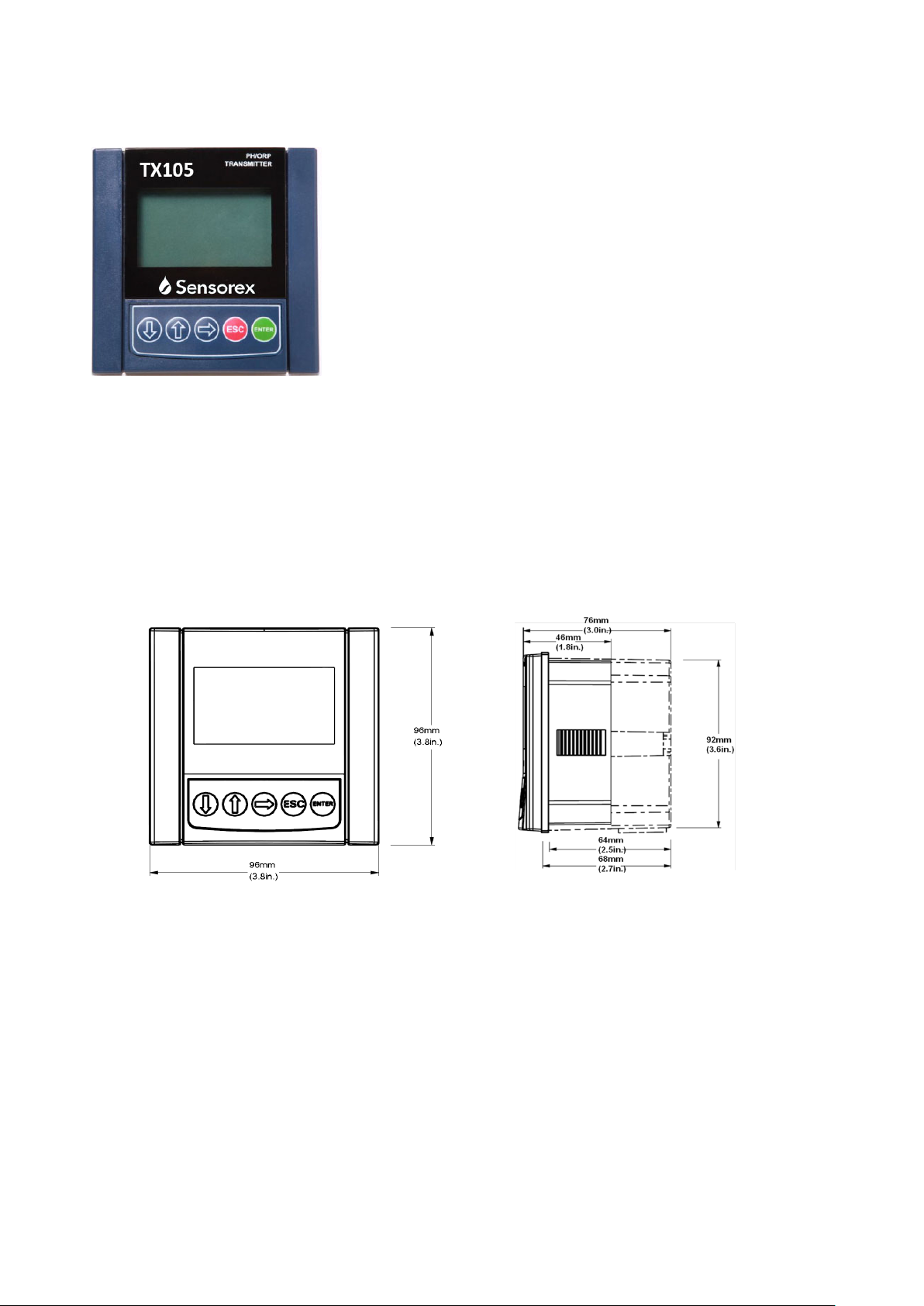
2.1 Front and Side View
Front view Side view
Panel Mount& Field Mount
2.2 Installation
TX105 pH/ORP transmitters are available in two installation styles: panel mount and field
mount.
2.2.1 Panel Installation Instructions
1) The panel mount version is designed for installation using a 1/4 DIN Punch.
2) Recommended clearance on all sides between instruments is 1 inch.

5
3) Slide the gasket over the back of the instrument.
4) Place the instrument into the panel cut-out.
5) Attach the mounting bracket to the back of the instrument by pulling apart the quick clips
and sliding it over the back of the instrument. Make sure that the quick clips are securely
attached to the latches.
6) Inspect the instrument to make sure that the instrument and the gasket are secured to the
panel appropriately.
7) To disassemble, press the clips of the mounting bracket against the panel and pull the
instrument away from the front.
Diagrammatic sketch:
Panel mount installation detail schematic
2.2.1.1 Panel Cut-Out

6
2.2.2 Field Mount Installation
The field mount version requires a wall mounting kit, which includes a plastic wall mounting rear
cover with gasket as well as fixing screws. This makes it possible to install the transmitter on a
variety of surfaces.
1) Place the gasket on the instrument.
2) Thread electrical cables through the connectors on the wall mounting rear cover.
3) Connect the power, sensor and OC output wires.
4) Secure the wall mounting rear cover to the front enclosure with screws.
5) Fix the wall mounting rear cover to the surface by using screws or cables.
Diagrammatic sketch:
Field mount installation detail schematic

7
3Specifications
Display:
LCD: 128*65 dot matrix, figure or alphabet: 12x8, 28x15, 32x18, etc.
Update rate: 1 second
Contrast: User selected, 5 levels
Measurement:
pH: 0.00 to 14.00 pH
ORP: -2000mv~+2000mv
Temperature: PT1000: 0 ~ 60 °C (32~ 140 °F)
Accuracy: ± 0.5% of reading
Repeatability*: ± 0.05% of span
Temperature drift*: Zero and Span: ± 0.02% of span per℃
*These performance specifications are typical at 25C
Electrical:
Power: 19 -48VDC, regulated, 30mA maximum
Current Output:
Isolated 4-20 mA output with 0.004 mA (12-bit) resolution
Update rate: 1 second
Maximum loop impedance: 250Ω@24V; 600Ω@31V; 1500Ω@48V
Memory:
Non-volatile: All user settings are retained indefinitely without battery backup
Open-Collector Output:
Isolated, 50 mA sink, 40 VDC maximum pull-up voltage
The OC output can be configured to be one of three modes below:
High mode
Low mode
Proportional pulses
Ambient Conditions:
8
Operation: -10 °C to 70 °C (14 °F to 158 °F); 0-95% relative humidity, non-condensing
Transport/storage: 15°C to 80°C (5°F to 176°F); 0-95% relative humidity, non-condensing
Standards and Approvals
CE: Certified Compliant to European Community Standards.
4Electrical Connections
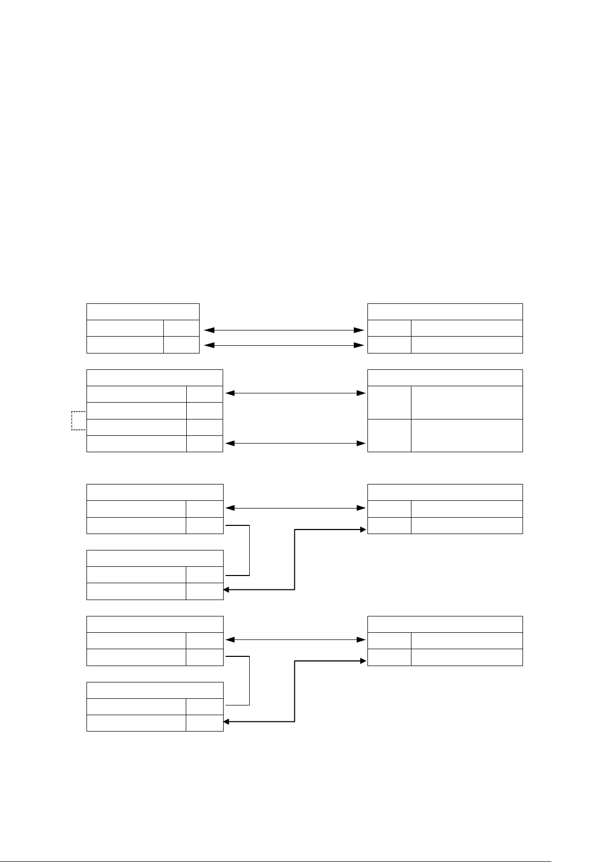
4.1 System Power & Loop Connections
Standalone application, loop current isn’t used
Power Supply
Transmitter Terminals
24VDC+
+
2
V+/Loop+
24VDC-
-
1
V-/Loop-
Connection to a PLC with built-in power supply.
PLC Terminals
Transmitter Terminals
24VDC+
+
2
V+/Loop+
24VDC-
-
4-20mA Loop Input
-
1
V-/Loop-
4-20mA Loop Input
+
Connection to a PLC with separate power supply
Option A
Power Supply
Transmitter Terminals
24VDC+
+
2
V+/Loop+
24VDC-
-
1
V-/Loop-
PLC
4-20mA Loop Input
-
4-20mA Loop Input
+
Option B
PLC
Transmitter Terminals
4-20mA Loop Input
-
2
V+/Loop+
4-20mA Loop Input
+
1
V-/Loop-
Power Supply
24VDC+
+
24VDC-
-

9
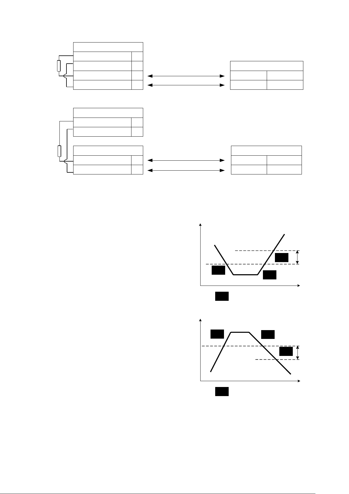
4.2 Sensor Input Connections
CAUTION:
• As electrical noise may interfere with electrode signal, please do not route the electrode cable in a
conduit containing AC power wiring.
PH Sensor Input Connections:
Sensor Input
Transmitter Terminals
TC-
coax center
9
Temp-
TC+
8
Temp+
REF
7
REF
PH
6
PH/ORP
Input
ORP Sensor Input Connections:
Sensor Input
Transmitter Terminals
10K Ohm Resistor customer
supplied
9
8
REF
7
REF
ORP
6
PH/ORP
Input
TX105
4.3 OC Output
4.3.1 Open Collector Output Connections
Connection to a PLC with built-in power supply
10K Ohm Resistor customer
supplied
10K Ohm Resistor
10K Ohm Resistor
Note: If sensor does not have
ATC, short TC- to TC+
coax braid
Red
Black
coax center
coax braid
10
PLC
Power Supply+
+
Power Supply-
-
Transmitter Terminals
OC input+
+
4
O.C.+
OC input-
-
3
O.C.-
Connection to a PLC, separate supply
Power Supply
24VDC+
+
24VDC-
-
PLC
Transmitter Terminals
OC input+
+
4
O.C.+
OC input-
-
3
O.C.-
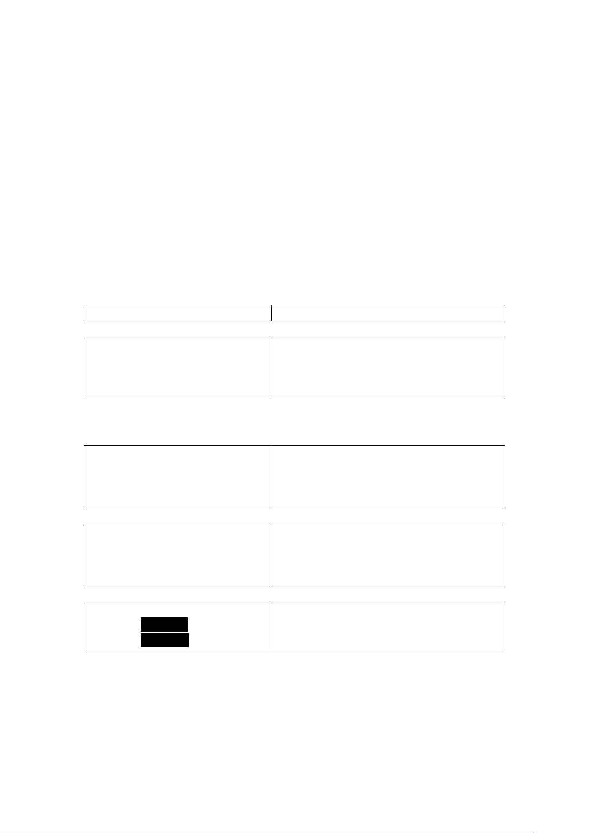
4.3.2 Open Collector Output Operation
The open collector output can be used as a switch or a warning that responds when the process value
moves above or below a set point, or it can be used
to generate a pulsing signal with a rate proportional
to the process value. The output can be disabled if
not used (select “OFF” in the OC OUTPUT menu).
The “parameter” mentioned below could be any of
the three: pH, ORP, or temperature.
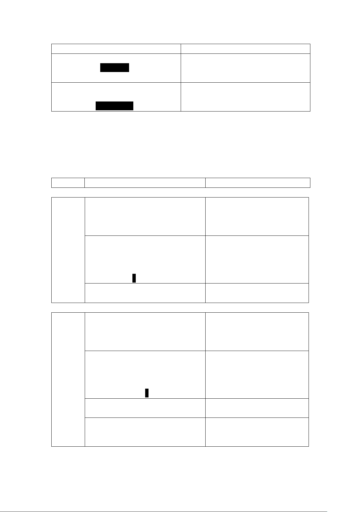
Low Mode:
In this mode, the OC output is only active when the
parameter is less than a user set point. The output
will be inactive when the parameter is larger than
the set point plus the hysteresis value.
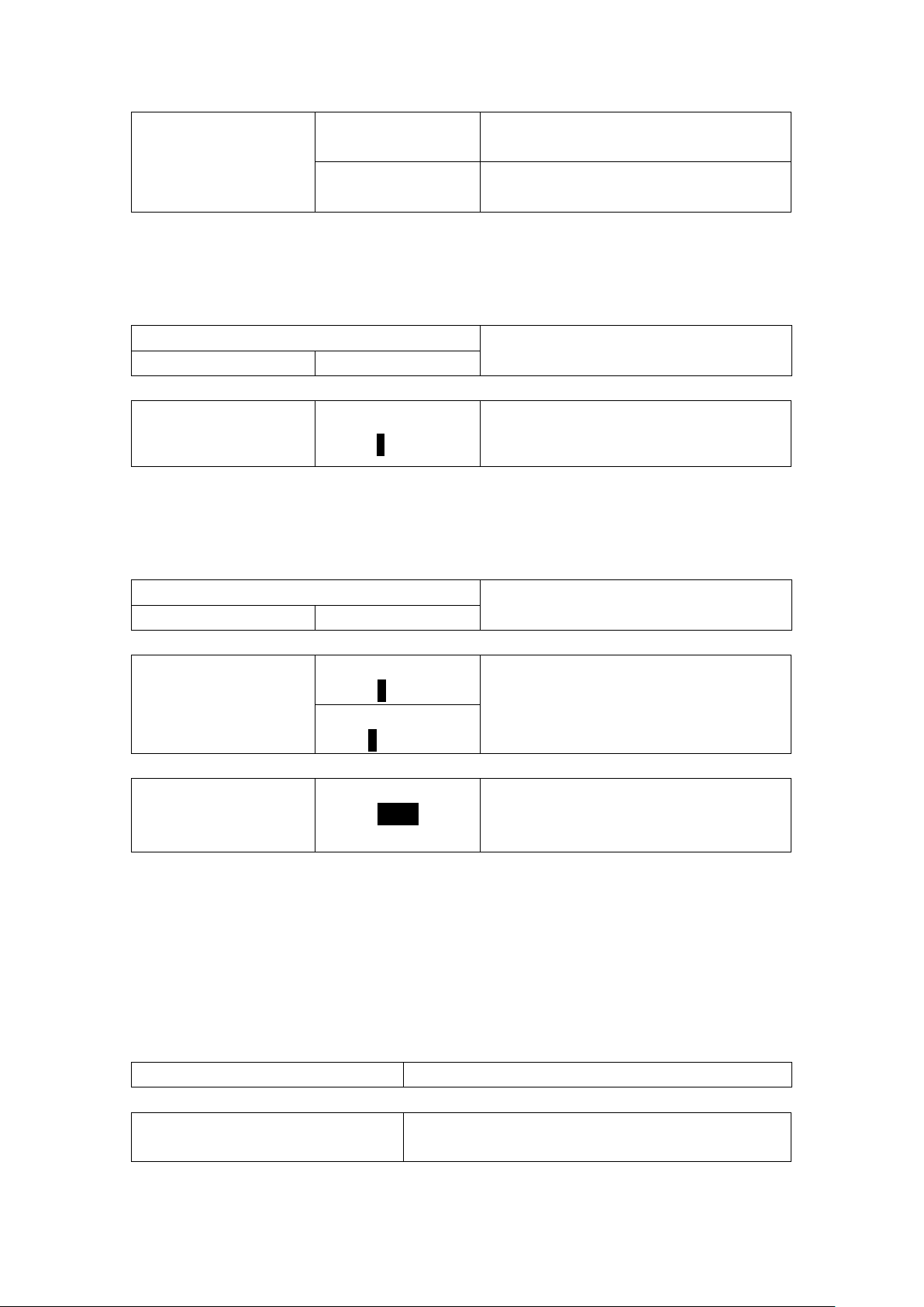
High Mode:
In this mode, the OC output is only active when the
parameter is larger than a user set point. The output
will be inactive when the parameter is smaller than
the set point minus the hysteresis value.
Proportional Pulsing
In this mode, the OC output will generate a pulse
sequence at the rate defined by the setting in the
OC OUTPUT menu.
In the example below, the starting point is pH=0.00,
the end point is pH=10.00 and the maximum frequency is 200 pulses/min:
• The output will be 0 pulses/min at pH values less than 0.0.
• The output will be 100 pulses/min at 5.00pH.
• The output will be 200 pulses/min at pH values above 10.00pH.
OC
OC
OC Low Setpoint
Hysteresis
Time
Value
N.O.
N.O.
OC
N.O.
:OC Output Active
:OC Output Inactive
OC OC
OC
High Setpoint
Hysteresis
Time
Value
N.O.
N.O.
OC
N.O.
:OC Output Active
:OC Output Inactive
100K
100K
11
5Menu
The menu consists of a view menu and an editable menu. The menu has several levels, with the
view menu being at the topmost level. You can loop within the same level menu items by
pressing the UP or DOWN arrow keys, move to a lower level menu by pressing the ENTER key,
and move to an upper level menu by pressing the ESC key. At any time, the system will return to
the view menu (default display) if no key is pressed for 10 minutes.
During normal operation, the view menu is displayed. Use the UP or DOWN arrow keys to select
the information you want displayed. The items will scroll in a continuous sequence. System
operations will not be interrupted during menu interaction.
5.1 View Menu for pH
Display
Description
Default display:
3.90 PH
22.1 ℃
Monitors the pH and temperature input from the sensor.
All of the displays below are temporary. The system will return to the default display if no keys
are pressed in 10 minutes.
Sensor Input
164 mV
Monitors the millivolt input from the pH electrode.
4~20mA Output
8.44 mA
Monitors the 4 to 20 mA loop output for the pH
measurement.
EasyCal
Press Enter
To Start >
Easy calibrates the system for the pH measurement.
5.1.1 EasyCal Details
12
Display
Description
EASY CALIBRATE
USE 4 7 10 >
USE DIN19267>
Calibrates the system with standard 4.0, 7.0, and
10.0 pH buffers
EASY CALIBRATE
USE 4 7 10>
USE DIN19267>
Calibrates the system using pH =4.65, pH=6.79,
and pH= 9.23 buffers, under DIN19267.
EasyCal procedures:
Only the 2 following buffers can be used by EasyCal:
1)Standard pH=4.00, pH=7.00, and pH=10.00
2)DIN 19267: pH =4.65, PH=6.79, and pH= 9.23
Set the sensor temperature before performing EasyCal for new electrode installations.
The procedure is the same for 1) and 2). Using 1) for an example:
EASYCAL 4 7 10:
Procedure
Display
Operation
Step
1
EASYCAL 4 7 10
Place Sensor
in pH Buffer
#1
Place the sensor in pH buffer 1, and
wait 30 seconds for the sensor to
stabilize.
EASYCAL Buffer #1
4.10 PH
173 mV
Please Select
47 10
Use the “RIGHT” key to navigate the
pH value options and press the
“ENTER” key to select.
Buffer #1
is Accepted!
No operation is required.
Step
2
EASYCAL 4 7 10
Place Sensor
in pH Buffer
#2
Place the sensor in pH buffer 2, and
wait 30 seconds for the sensor to
stabilize.
EASYCAL Buffer #2
7.10 PH
2 mV
Please Select
4 710
Use the “RIGHT” key to navigate the
pH value options and press the
“ENTER” key to select.
Buffer #2
is Accepted!
No operation is required.
EASY CALIBRATE
4 7 10
Successfully!
No operation is required.

13
Theoretical mV values(25℃)
PH
0
1
2
3
4
5
6
7
8
9
10
11
12
13
14
mV
414
355
296
237
177
118
59
0
-59
-118
-177
-237
-296
-355
-414
5.2 View Menu for ORP
Display
Description
Default display:
ORP
366
mV
Monitors the ORP value.
All of the displays below are temporary. The system will return to the default display if no keys
are pressed in 10 minutes.
Sensor Input
164 mV
Monitors the millivolt input from the ORP electrode.
4~20mA Output
8.44 mA
Monitors the 4 to 20 mA loop output for the ORP
measurement.
5.3 Editable Menu
5.3.1 Editing Procedure
Step 1. Press and hold the ENTER key for 3 seconds to enter Main Menu:
If a password is required, enter the correct key code. The key code is entered by
pressing the RIGHT-DOWN-UP-DOWN keys in sequence.
The system will return to the view menu if no key is pressed for 10 minutes.
Step 2. Navigate the menu with the UP and DOWN keys.
The selected menu is highlighted; press ENTER to edit the menu.
Only the highlighted item can be edited.
No parameters will be saved if the ESC key is pressed, and the display will return to
the previous menu.
The system will return to the view menu if no key is pressed for 10 minutes.

14
Tip: CALIBRATION > is highlighted whereas CALIBRATION> is not highlighted.
Step 3. Press ENTER key to save the new settings and return to Step 2.
NOTE:
ESC can be pressed at any time, and the system will exit the current level without saving.
The edited value is effective immediately after pressing the ENTER key.
Repeat steps 2 and 3 as needed.
5.3.2 Main Menu
CALIBRATION >
OUTPUT>
OPTIONS >
Press the UP or DOWN arrow keys to navigate the three items. Press the ENTER key to enter the
CALIBRATION menu, the OUTPUT menu, or the OPTIONS menu. Press the ESC key to return to the
view menu.
5.3.3 Calibration Menu for pH
Display
Description
Menu Item
Next Level Menu
TEMPERATURE UNIT >
℃
Set Temp Unit
℃℉
Sets the temperature unit.
TEMPERATURE>
+20℃
Set Temperature
+20.0 ℃
Sets the temperature. This should be done
before using EasyCal or standard/slope
calibration.
STANDARD/SLOPE
CALIBRATION>
Applies standard/slope calibration to the pH
measurement.

15
5.3.3.1 Standard/slope Calibration Details
Display
Operation
Standard/Slope
Place Sensor
In pH Buffer
#1
Place sensor In pH Buffer #1, and wait 30 seconds
for the sensor to stabilize.
STANDARD/SLOPE
Buffer#1
0mV 7.00PH
Set Standard
00.00
Set the pH value for Buffer #1.
Buffer #1
is Accepted!
No operation is required.
Standard/Slope
Place Sensor
In pH Buffer
#2
Place sensor In pH Buffer #2, and wait 30 seconds
for the sensor to stabilize. The pH values of
Buffer#2 and Buffer #1 shouldn’t be too close.
STANDARD/SLOPE
Buffer#2
177mV 4.01PH
Set Slope
00.00
Set the pH value for Buffer #2.
Buffer #2
is Accepted!
No operation is required.
Standard/Slope
Calibrate
Successfully!
No operation is required.
5.3.4 Output Menu for pH
Display
Description
Menu Item
Next Level Menu
Output 4~20mA>
4~20mA Source>
PH
Sets either pH or temperature as the source
for the 4~20mA current loop output.
Set 4~20mA>
Sets the minimum and maximum
pH/temperature values for the 4~20mA
current loop output.

16
OC Output >
OC SOURCE>
PH
Selects pH or temperature as the source for
the open collector output.
OC MODE>
PULSE
See 4.3.2 Open Collector Output Operation;
sets the OC mode and relative parameters.
The next two sections (5.3.4.1 and 5.3.4.2) use pH as an example, but all of the operations are
the same for temperature.
5.3.4.1 Set 4~20mA Details for PH
Menu Item
Description
Set 4mA Output>
0.00 pH
Sets the pH value for 4mA current loop output.
Set 20mA Output>
14.00 pH
Sets the pH value for 20mA current loop output.
5.3.4.2 OC Output Details for PH
Display
Description
Menu Item
Next Level Menu
MIN ALARM
MIN SETPIONT>
00.00 pH
As described in 4.3.2, sets the minimum
point for low mode. The OC output is active
when the pH value is less than the set value.
HYSTERESIS>
00.10 pH
As described in 4.3.2, sets the hysteresis
value for low mode. The OC output is
inactive when the pH value is greater than
the sum of the minimum point and the
hysteresis value.
MAX ALARM
MAX SETPIONT>
10.00 pH
As described in 4.3.2, sets the maximum
point for high mode. The OC output is active
when the pH value is greater than the set
value.
HYSTERESIS>
00.50 pH
As described in 4.3.2, sets the hysteresis
value for low mode. The OC output is
inactive when the pH value is less than the
maximum point minus the hysteresis value.
Note: the hysteresis value must be less
than the maximum point.
17
PULSE
RANGE >
00.0014.00 pH
As described in 4.3.2, sets the range.
PULSE RATE>
200 Pulse/min
As described in 4.3.2, sets the pulse rate.
5.3.5 Calibration Menu for ORP
Display
Description
Menu Item
Next Level Menu
STANDARD >
000mv
One Point Cal
0000 mV
Applies a linear calibration to the ORP
measurement.
5.3.6 Output Menu for ORP
Display
Description
Menu Item
Next Level Menu
Output >
4~20mA
Set 4mA Output>
-2000mV
Sets the minimum and maximum ORP
values for the 4 to 20 mA current loop
output.
The valid value range is -2000~+2000 mV.
Set 20mA Output>
2000 mV
OC Output >
OC MODE>
PULSE
See 4.3 Open Collector Output Operation,
selects the OC mode and relative
parameters.
The OC output details for ORP are the same as pH, see section 0.
5.3.7 Options Menu
The Options Menu is the same for both pH and ORP.
Display
Description
CONTRAST >
Level 1
Adjusts the LCD contrast for optimal viewing. A setting of 1
is the lowest contrast, while a setting of 5 is the highest.

18
FILTER >
1S
Sets the time parameter for averaging input values, There
are 8 Options: 1S, 2S, 5S, 8S, 10S, 20S, 40S, and 60S.
Note: Larger filter values mean more stable displays but
longer response times. Please consider your system
safety requirements.
LOOP ADJUST 4mA >
3.75
Adjusts the minimum current output to match the external
current measurement. Adjustable from 3.70 mA to 5.00 mA.
LOOP ADJUST 20mA >
21.00
Adjusts the maximum current output to match the external
current measurement. Adjustable from 19.00 mA to 21.00
mA.
TEST 4~20mA
OUTPUT
Press the UP and DOWN arrow keys to manually select any
output current value from 3.7 mA to 21.00 mA to test the
current loop output. The value changes 0.01mA each time
the UP/DOWN key is pressed. If the UP/DOWN key is
pressed and held for more than 5 seconds, The value will be
adjusted by 0.1mA continuously.
TEST OC
OUTPUT
Press the UP and DOWN arrow keys to manually select the
state of the open collector output.
PASSWORD MENU
OFF
Selects whether or not the password is needed to enter the
Main Menu. Note: the password is input by pressing the
RIGHT-DOWN-UP-DOWN arrow keys in sequence and
cannot be changed.
RESTORE FACTORY SETTINGS>
Restores factory settings. In order to do so, you must enter
the correct key code. The key code is input by pressing the
RIGHT-DOWN-UP-DOWN arrow keys in sequence.

19
6Troubleshooting
Display
Possible Cause
Suggestions
Please wait 30s
for sensor
stabilization!
During pH EasyCal or
Standard/Slope calibration,
when “Place Sensor in pH
Buffer #1(or 2)” is prompted,
the “Enter” key is pressed
within 30 seconds.
Wait 30 seconds
Please Check
Sensor!
1. During pH EasyCal, the
detected sensor input is
more than 2PH away from
the selected pH value or
the range of possible
buffer values.
2. During pH Standard/Slope
calibration, the detected
sensor input is more than
2PH away from the
entered pH value.
3. During ORP One Point
calibration, the detected
sensor input is more than
120mV away from the
entered ORP value.
1. Check the sensor and restart
the calibration procedure.
2. Press “Enter” to accept the
value.
Please Maintain
or Replace
Sensor!
1. During pH EasyCal, the
detected sensor input is
more than 4PH away from
the selected pH value or
the range of possible
buffer value.
2. During pH Standard/Slope
calibration, the detected
sensor input is more than
4PH away from the
entered pH value.
3. During ORP One Point
calibration, the detected
sensor input is more than
240mV away from the
entered ORP value.
1. Press “Enter” to interrupt the
calibration. Replace the
sensor and restart the
calibration procedure.
2. Press “ESC” to reenter or
reselect the pH or ORP value.

20
Buffer #2 is
too close
to
Buffer #1
1. During pH EasyCal 4 7 10
or Standard/Slope
calibration, buffer 2 is
within 2PH of buffer 1.
2. During pH EasyCal
DIN19267 calibration,
buffer 2 is within 1PH of
buffer 1.
Check buffers.
1. Replace Buffer #2 with a
buffer of the appropriate pH
value and continue the
calibration.
2. Press “ESC” to interrupt the
calibration when “Place
Sensor in pH Buffer #2” is
prompted again. Restart the
calibration with appropriate
buffers.
Value Must
Be Larger
Than -10°C(or 14°F)!
During temperature
calibration, the entered value
is smaller than -10°C(or 14°F).
Enter the appropriate value.
Value Must
Be Smaller
Than 70°C(or 158°F)!
During temperature
calibration, the entered value
is larger than 70°C(or 158°F).
Enter the appropriate value.
Value
Too Large(or Small)!
During temperature
calibration, the entered value
is more than 25 degree away
from the detected value.
1. Check the sensor and restart
the calibration procedure.
2. Enter the appropriate value.
HYSTERESIS Too Large
The HYSTERESIS is greater
than the MAX SETPOINT
Set HYSTERESIS to a smaller value
than MAX SETPIONT.
Wrong Password
The password is wrong.
Enter correct password.
Table of contents
Other Sensorex Transmitter manuals

Sensorex
Sensorex TX3000 User manual

Sensorex
Sensorex TX3100 User manual

Sensorex
Sensorex TX2000 User manual

Sensorex
Sensorex CX105 User manual

Sensorex
Sensorex CT-1000 User manual

Sensorex
Sensorex TX2000 User manual

Sensorex
Sensorex CX100 User manual

Sensorex
Sensorex TX2000 User manual

Sensorex
Sensorex TX100 Specification sheet
Popular Transmitter manuals by other brands


PCB Piezotronics
PCB Piezotronics 477A05 Installation and operating manual

RKI Instruments
RKI Instruments 65-2331RK Operator's manual

Extron electronics
Extron electronics TP Series Setup guide

YOKOGAWA
YOKOGAWA YTA610 user manual

FlowLine
FlowLine EchoPod DL34 Series quick start

Simu
Simu LiveIn2 instructions