Sensorex TX3100 User manual
TX3100
Microprocessor
pH/ORP
Transmitter
Operation
Manual
TX3100

2
CONTENTS
Precautions for Installation
Brief Instructions ................................................................................................................................. 4
1. Specifications .................................................................................................................................... 7
2. Assembly and Installation
2.1 Transmitter Installation ................................................................................................................ 8
2.2 Panel Mounting Illustration ......................................................................................................... 8
2.3 Wall Mounting and Pipe Mounting Illustration ........................................................................... 9
2.4 Electrode and Housing Assembly .............................................................................................. 10
2.5 Round Junction Box Illustration and Description ...................................................................... 13
2.6 Rectangular Junction Box Illustration and Description ............................................................. 16
3. Overview of pH/ORP Transmitter TX3100
3.1 Rear Panel Illustration ............................................................................................................... 19
3.2 Terminal Function Illustration ................................................................................................... 19
3.3 Terminal Function Description .................................................................................................. 20
3.4 Accessorial Transmitter PH-300T Installation (Optional) ......................................................... 21
3.5 Transmitter and Accessorial Transmitter PH-300T Connection ................................................ 22
3.6 Wiring Illustration ...................................................................................................................... 23
3.7 Electrical Connection Illustration .............................................................................................. 24
3.8 Online pH/ORP Measurement System (Optional) ..................................................................... 25
4. Configuration
4.1 Front Panel Illustration .............................................................................................................. 26
4.2 Keypad ....................................................................................................................................... 26
4.3 LED Indicators ........................................................................................................................... 26
4.4 Display. ...................................................................................................................................... 27
5. Operation
5.1 Measurement Mode ................................................................................................................... 28
5.2 Settings Menu ............................................................................................................................ 28
5.3 Calibration Menu ....................................................................................................................... 28
5.4 Shortcuts .................................................................................................................................... 28
5.5 Default Values ............................................................................................................................ 28
6. Settings
Settings Block Diagram ................................................................................................................... 30
6.1 Settings Menu ............................................................................................................................ 32
6.2 Settings Security Code (Code) ................................................................................................... 33
6.3 Language .................................................................................................................................... 34
6.4 Measurement Parameter (Mode) ............................................................................................... 35

3
6.5 Multi-Point Calibration (Multi-Cal) .......................................................................................... 36
6.6 Temperature ............................................................................................................................... 37
6.7 Relay 1 ....................................................................................................................................... 38
6.8 Relay 2 ....................................................................................................................................... 39
6.9 Clean .......................................................................................................................................... 40
6.10 Analog Output 1 (pH/ORP) ..................................................................................................... 41
6.11 Analog Output 2 (Temperature) ............................................................................................... 42
6.12 Date/Time (Clock) ................................................................................................................... 43
6.13 Sample Measurement Average (Digital Filter) ........................................................................ 44
6.14 Back Light ................................................................................................................................ 45
6.15 Contrast .................................................................................................................................... 46
6.16 Automatic Return (Return) ...................................................................................................... 47
7. Calibration
Calibration Block Diagram .............................................................................................................. 48
7.1 Calibration Menu ....................................................................................................................... 49
7.2 Calibration Security Code (Code) .............................................................................................. 50
7.3 pH Calibration ............................................................................................................................ 51
7.4 ORP Calibration ......................................................................................................................... 55
7.5 Automatic Return (Return) ........................................................................................................ 56
8. Error Messages (Error Codes) ...................................................................................................... 57
9. Maintenance ................................................................................................................................... 58
Appendix ............................................................................................................................................. 59

4
Brief Instructions
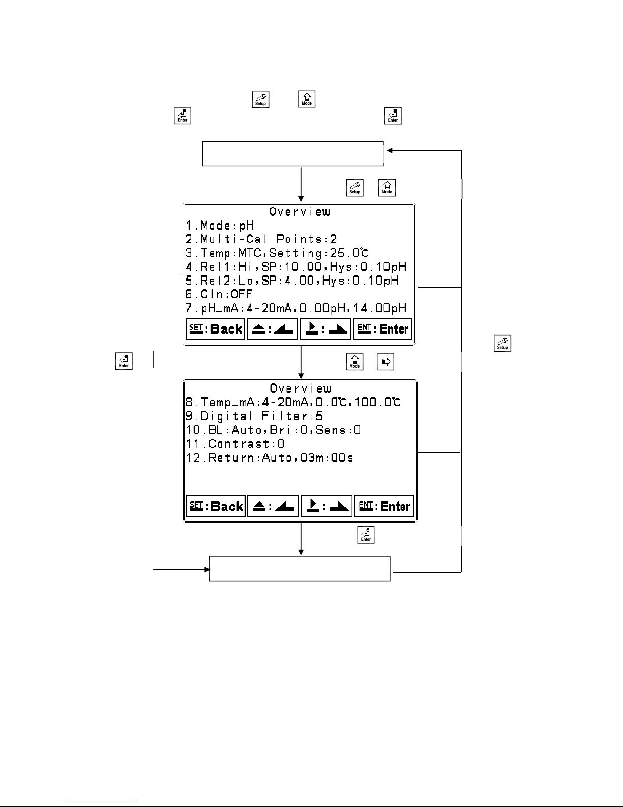
◎Settings Menu Description (See Chapter 6 for Details)
Press and simultaneously to display settings information overview. Press_____to enter
settings menu. Press keypad according to the index bar at the bottom of the screen.
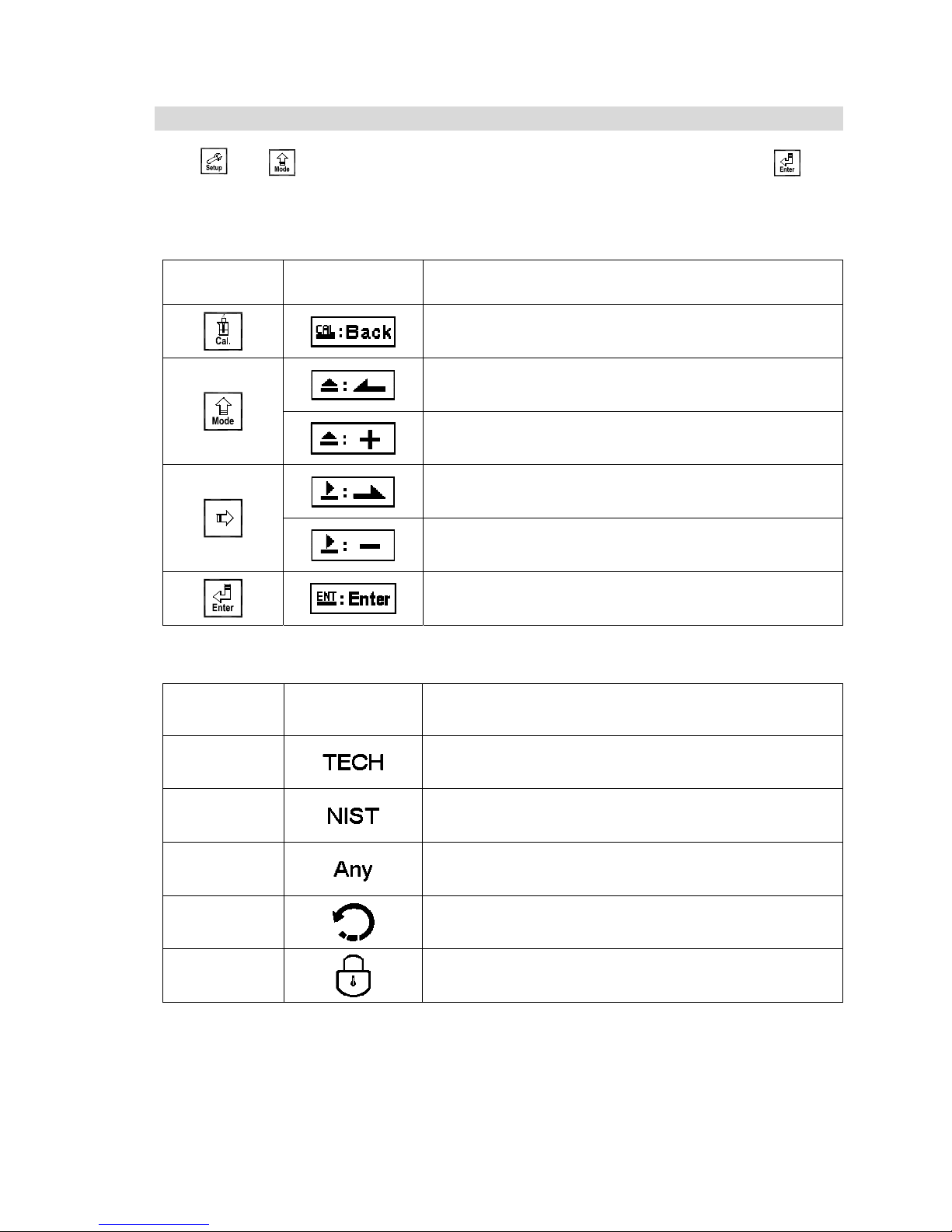
Keypad Index
Keypad Index Bar Description
Return to previous level or action
Left or left page
Increase digit
Right or right page
Decrease digit
Confirm and proceed to next step
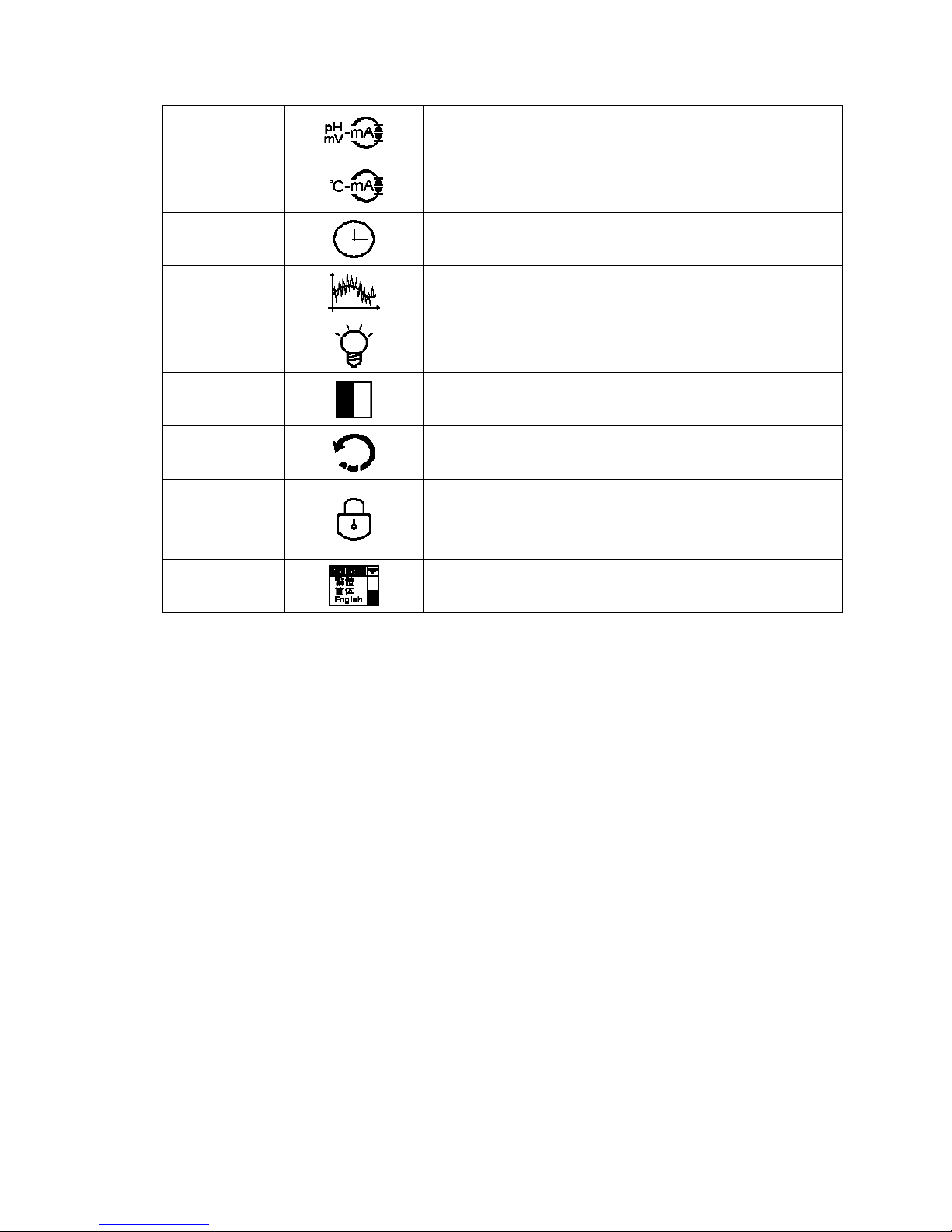
Settings Items
Function Icon Description
Mode Measurement mode, select pH or ORP measurement
Multi-Cal. Multi-point calibration, adjust number of points
(PC-3310 provides up to three point calibration)
Temperature
Temperature measurement and compensation,
MTC - Manual temperature compensation
PTC/NTC - Auto temperature compensation
Relay 1 First relay settings, select Hi/Lo alarm or OFF
Relay 2 Second relay settings, select Hi/Lo alarm or OFF
Clean Automatic wash time settings
Set cleaning relay ON/OFF duration
5
Analog 1 Current output corresponding to pH or ORP range
Analog 2 Current output corresponding to temperature range
Clock Time and date settings
Digital Filter Digital filter settings, adjust number of samples to be
averaged for each reading
Back Light Backlight settings, set backlight Auto/ON/OFF,
brightness, and sensitivity
Contrast Screen contrast settings
Return Measurement mode return settings
Code
Settings passcode setup, the settings passcode is
precedential to the calibration passcode and can be used to
bypass calibration lock
Language Available in English, Traditional Chinese, and Simplified
Chinese
6
◎Calibration Menu Description (See Chapter 7 for Details)
Press and simultaneously to display calibration information overview. Press_____to
enter calibration menu. Press keypad according to the index bar at the bottom of the screen.
Keypad Index:
Keypad Accordingly item Description
Return to previous level or action
Left or left page
Increase digit
Right or right page
Decrease digit
Confirm and proceed to next step
Calibration Items:
Function Icon Description
TECH Use TECH buffers as standard solution for calibration
NIST Use NIST standard buffers (DIN 19266) as standard
solution for calibration
Any Use any buffer solution by users’ definition for calibration
Return Measurement mode return settings
Code Calibration passcode setup
7
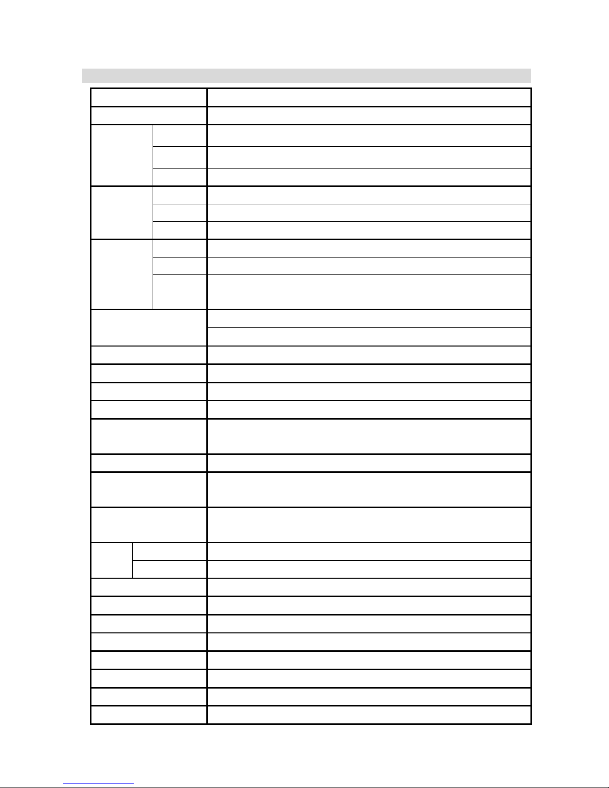
1.Specifications
Model TX3100
Measurement Modes pH/ORP/Temp
Range
pH -2.00~16.00 pH
ORP -1999~1999 mV
TEMP -30.0~130.0˚C
Resolution
pH 0.01 pH
ORP 1 mV
TEMP 0.1˚C
Accuracy
pH ±0.01 pH (±1 Digit)
ORP ±0.1% (±1 Digit)
TEMP ±0.2˚C (±1 Digit)
with temperature error correction
Temperature
Compensation
NTC30K / PT1K Auto temperature compensation
Manual temperature compensation
Calibration Mode TECH, NIST, Any Buffer, up to three point calibration
Ambient Temp. 0~50˚C
Storage Temp. -20~70˚C
Input Impedance > 1012Ω
Display Large LCM with backlight sensor and contrast adjustment;
Text mode
Language Available in English, Traditional Chinese, Simplified Chinese
Analog Output 1 Isolated DC 0/4~20 mA corresponding to main measurement,
Max load 500Ω
Analog Output 2 Isolated DC 0/4~20mA corresponding to temperature,
Max load 500Ω
Settings Contact RELAY ON/OFF contact, 240VAC 0.5A Max (recommended)
Activate Hi/Lo, Hi/Hi, Lo/Lo, selectable two limited programmable, ON/OFF
Wash RELAY contact, ON 0~99 min 59 sec / OFF 0~999 hr 59 min
Voltage Output DC±12V, 1W Max for PH-300T (Optional)
Protection IP65
Power Supply 100V~240VAC±10%, 6W Max, 50/60Hz
Installation Wall / Pipe / Panel Mounting
Dimensions 144 mm × 144 mm × 115 mm (H×W×D)
Cut off Dimensions 138 mm × 138 mm (HW)
Weight 0.8 kg

8
2. Assembly and Installation
2.1 Transmitter Installation
This transmitter can be installed by panel mounting, wall mounting, or 2” pipe mounting.
Panel Mounting:
Prepare a square hole of 138 mm x 138 mm on the panel box, then insert the controller directly
into the hole. Insert the accessorial mounting bracket from the rear, and fix into the pickup groove.
2.2 Panel Mounting Illustration
Min. 200 mm
Min. 200 mm
Hole distances on the panel box
Panel mounting illustration,
fixed with mounting bracket
138 mm
138 mm
Hole size
++
+
+
Mounting bracket
90 mm
10
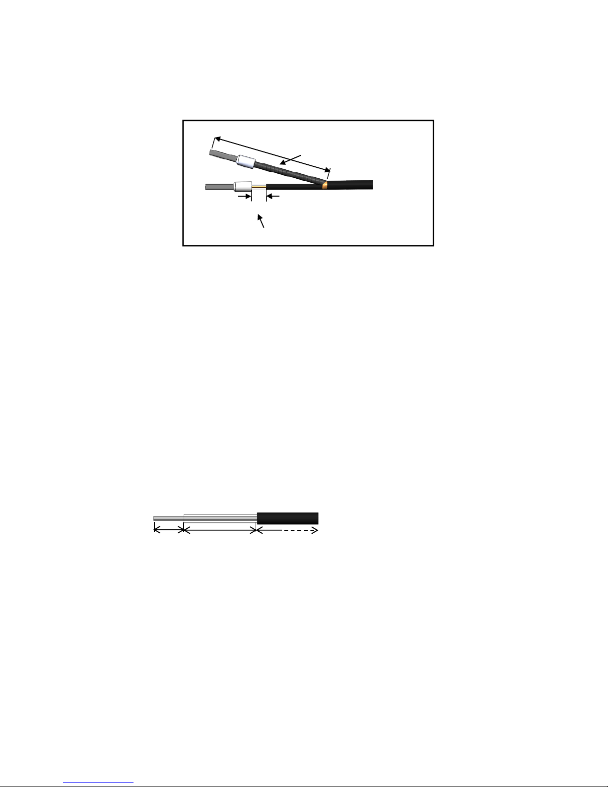
Put heat-shrinkable
sleeve on coaxial shield
2.4 Electrode and Housing Assembly
2.4.1 Cable Preparation (Cable Stripping Procedure)
a. Strip off approximately 40 mm of the pH/ORP coaxial cable jacket; separate the coaxial inner
wire and coaxial shield wire as seen in the illustration above.
b. Make sure to remove the conductive rubber of the coaxial inner as seen in the following
illustration.
c. Put heat-shrinkable sleeve on the coaxial shield.
d. Attach connection tips on both ends of coaxial inner and coaxial shield.
e. Extend the cable to the transmitter without any joints except at the junction box. Connect the
transparent coaxial inner directly to the GLASS terminal on the back of transmitter, then
connect the metal coaxial shield to the REF terminal.
pH/ORP Signal Cable Preparation Instruction:
Refer to the cable preparation illustration above. Peel 5 mm of the black conductive rubber wrap
on the coaxial inner away from the connection tip.
The length of the separated coaxial inner and coaxial shield wires is suggested to be approx. 40
mm for the convenience of wiring.
6mm 12mm Conductive rubber
Coaxial Inner Stripping Illustration
Transparent coaxial inner
(Peel away conductive rubber)
5mm
40mm
pH/ORP Cable Preparation

19
3. Overview of pH/ORP Transmitter TX3100
3.1 Rear Panel Illustration
3.2 Terminal Function Illustration
POWER
WASH/Cln
2
4/20m
A
+
-
±12V
+
-
REL2REL1
AC
INPUT
POWER
1
4/20m
A
+
-
Temp
(T/PShield)
SG
T/P
GLASS
REF
pH/
ORP

20
3.3 Terminal Function Description
1
2
3
4
5
6
7
8
9
10
11
12
13
14
15
16
17
18
19
20
100~240 AC: Power supply terminal
WASH: Wash relay contact for an external relay
REL2: Second alarm control, contact for an external relay
REL1: First alarm control, contact for an external relay
NC / D-(A): No contact
4~20mA - terminal / G: Temperature current output terminal -, for external
recorder or PLC control
4~20mA + terminal / D+(B): Temperature current output terminal +, for
external recorder or PLC control
4~20mA - terminal: Master measure current output terminal -, for external
recorder or PLC control
4~20mA + terminal: Master measure current output terminal +, for external
recorder or PLC control
DC±12V: Output terminal of direct current voltage ±12V
T/P: Connect with one of cable end of temperature probe
SG: Solution ground wire. In a two-wire distribution system, the
terminals SG and REF should be short circuited with a terminal cross
jumper slice (included and attached as factory default).
REF: Coaxial shield of pH/ORP electrode signal wire
NC: No contact
GLASS: Coaxial inner of pH/ORP electrode signal wire
23
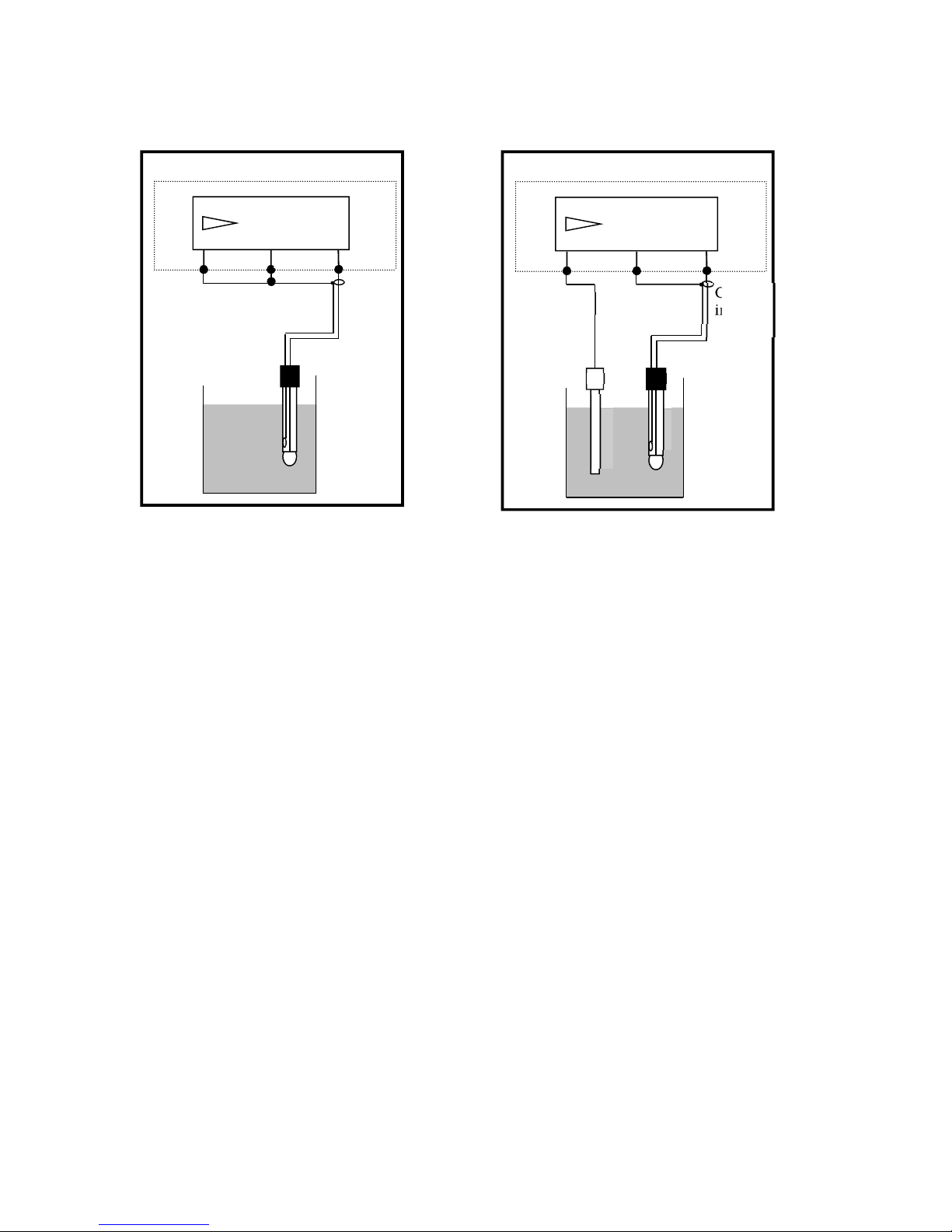
3.6 Wiring Illustration
Three-Wire Distribution
GND REF. GLAS
pH/
ORP
Coaxial
inner
Coaxial
shield
Black
Two-Wire Distribution
GND REF. GLAS
pH/
ORP
Coaxial
inner
Coaxial shiel
d
Short circuit slice
24
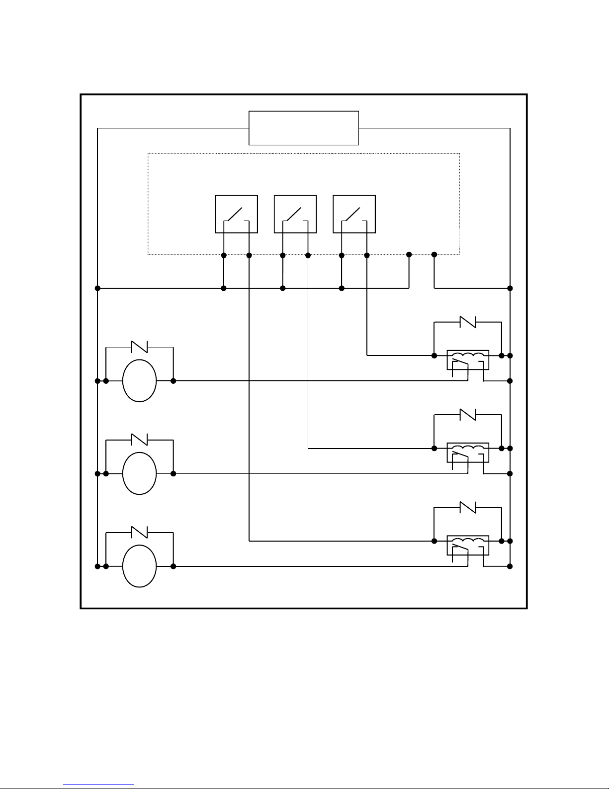
3.7 Electrical Connection Illustration
100V~240VAC
Relay 2 Relay 1 WASH/Cln
100V~240VAC
Transmitter
Cleaning device
Surge absorber
M
Surge absorber
External relay
Dose feeder
Surge absorber
M
Dose feeder
Surge absorber
M
Surge absorber
External relay
Surge absorber
External relay
Note: The transmitter’s built-in miniature relays are required to be repaired and replaced by professional
technicians. External relays (Power Relay) must be connected to activate external devices.

26
4. Configuration
4.1 Front Panel Illustration
4.2 Keypad
In order to prevent unauthorized operations, the transmitter utilizes multi-key and passcode functions
to enter parameter and calibration setting modes. Description of the key functions are as follows:
:When in settings menu, press this key to exit and return to measurement mode.
: When in calibration menu, press this key to exit and return to measurement mode.
:1. When in settings or calibration menu, press this key to move left or return to the
previous page.
2. When adjusting values, press this key to increase the digit.
:1. When in settings or calibration menu, press this key to move right or to advance to the
next page.
2. When adjusting values, press this key to decrease the digit.
:Key for confirmation; press this key to confirm data values or select menu items.
4.3 LED Indicators
WASH : Washing device operation indicator
RELAY1: Dosage control operation indicator (Relay 1)
RELAY2: Dosage control operation indicator (Relay 2)
B.L. : Light sensor; under automatic display backlight mode, the indicator will light up when
the surrounding brightness changes.
TX3100
27
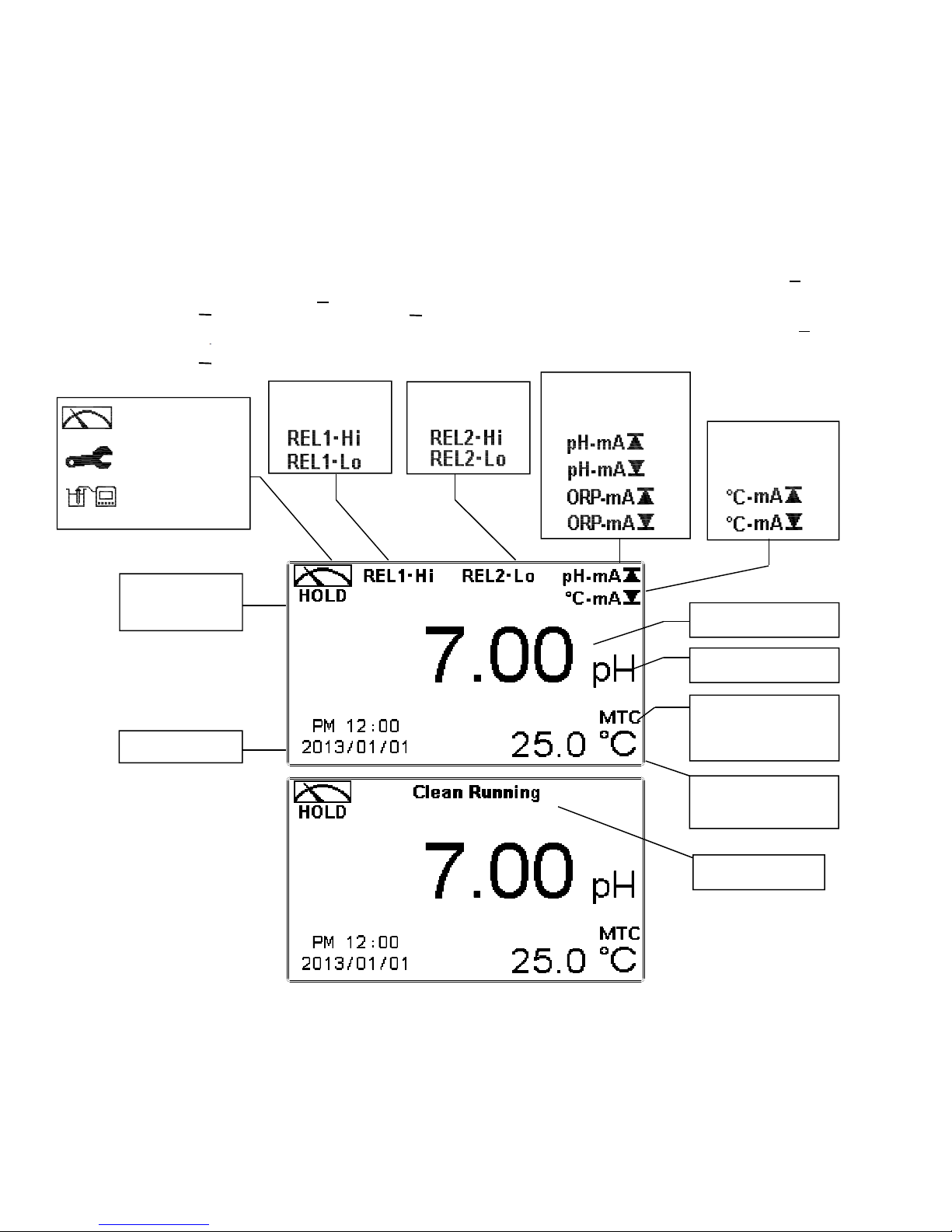
4.4 Display
1. When clean function is activated, the display will show “HOLD” and flash “Clean Running”. At the same
time, the WASH indicator LED will light up, and the transmitter will automatically turn off Relay 1 and
Relay 2 function. After cleaning is completed, both Relay 1 and Relay 2 will automatically return.
2. When Relay 1/Relay 2 Hi settings are activated, the display will flash “REL1-HI/ REL2-HI”, and the
RELAY1/RELAY2 indicator LED will light up. When Relay 1/Relay 2 Lo settings are activated, the
display will flash “REL 1-Lo/ REL 2-Lo”, and the RELAY1/RELAY2 indicator LED will light up.
3. When the Analog 1 current output exceeds the upper/lower limit, the display will flash “pH-mA / pH-
mA ” or “ORP-mA / ORP-mA ”.
4. When the Analog 2 current output exceeds the upper / lower limit, the display will flash “˚C-mA / ˚C -
mA ”.
Note: The “HOLD” warning text appears when clean function is activated, or when entering setup menu, or when
entering calibration menu. Under HOLD status, the corresponding display and output are as follows:
1. Both Relay 1 and Relay 2 cease from action. When entering settings menu or calibration menu under
clean status, the instrument will pause cleaning automatically.
2. The current output which corresponds to measurement value, will remain at the last output value before
HOLD status.
Analog 1 output
current over range
alarm
REL 2 high or
low point alarm
:
Measurement mode
:
Set-up mode
:
Calibration mode
Analog 2 output
current over range
alarm
Control function
on hold
REL 1 high or
low point alarm
Cleaning in action
Measurement Unit
Time and Date
Temperature
Compensation Mode
(MTC/ATC)
Temperature Value
Measurement Value
▲
▲
▼
▲
▼
▼

28
5.Operation
5.1 Measurement Mode
After all electrical connections are secured and tested, connect the instrument to the power supply
to turn it on. The transmitter will automatically enter measurement mode with the factory default
settings or the previous user settings.
5.2 Settings Menu
Please refer to the settings instructions in Chapter 6. Press and simultaneously to enter
settings menu, or press to return to measurement mode.
5.3 Calibration Menu
Please refer to the calibration instructions in Chapter 7. Press and simultaneously to enter
calibration menu, or press to return to measurement mode.
5.4 Shortcuts
Under measurement mode, if MTC is selected for temperature compensation mode, you may
press_____or_____to adjust the MTC temperature value.
5.5 Default Values:
5.5.1 Settings Default Values
Measurement Mode: pH
Multi-Cal: 2 points
Temperature Compensation: MTC 25˚C
Relay 1: High point alarm: AUTO, SP1 = 10.00 pH, Hys = 0.10 pH
Relay 2: Low point alarm: AUTO, SP2 = 4.00 pH, Hys = 0.10 pH
Wash Time: OFF
Analog 1 current output (pH/ORP): 4~20 mA, 0.00~14.00 pH
Analog 2 current output (Temp): 4~20 mA, 0~100.0˚C
Date & Time: 2013/1/1 00:00:00
Digital Filter: 5
Backlight: Off
Contrast: 0
Return: Auto, 3 minutes
Code: OFF

29
5.5.2 Calibration Default Values:
Calibration Type: TECH-No Cal
Slope: -59.15 mV/pH @ 25.0˚C
Asy: 0 mV
Sensitivity: 100.0%
Determination:1.0000
Calibration Value: None data
Return: Auto, 3 minutes
Codep: OFF
Note: The factory default calibration setting is “No Cal”, and the calibration value is “None”. This means
that the user has not yet calibrated the sensor with the transmitter. After every calibration, the display
will show the calibration type and the calibration value. However, if the transmitter has not yet been
calibrated, it takes the pre-set Asy and Slope into measurement.

30
6.Settings
Settings Block Diagram – Part 1
Overview
Mode
Setting
Code
Setting
Temperature
Setting
Relay 1
Setting
Relay 2
Setting
Multi-Cal.
Setting
Input
Code
OFF ON
New
Code
Select
pH/ORP
Mode
MTC NTC
Relay 1
SP Input
Relay 1
Hys. Input
Select
Relay 1
On/Off
Relay 1
Test
Relay 2
Hys. Input
Select
Relay 2
On/Off
Relay 2
Test
Relay 1
SP Input
Select
No. of
Points
PTC
Value
Input
Value
Correct
Value
Correct
Select
Relay 1
Hi/Lo
Select
Relay 2
Hi/Lo
English
Tradi-
tional
Chinese
Simpli-
fied
Chinese
Clean
Setting
Auto
Return
Setting
Auto Auto
Language
Setting
:
:
:
:
Return to previous
level/action
Continue on next page

31
Settings Block Diagram – Part 2
Clean
Setting
Analog 1
pH/ORP
Output 1
Analog 2
Temp.
Output 2
Clock
Setting
Digit Filter
Setting
Input
Shut down
Time
Input Clean
Hys. Time
Clean
Test
Input
Clean
Active Time
Value corr. to
0 or 4mA
Value corr. to
20mA
Value corr.
to 0 or 4mA
Value corr.
to 20mA
Select
0~20mA or
4~20mA
Set Year
Set Date
Set Time
Number of
Signal
Average
Select
0~20mA or
4~20mA
Back Light
Setting
Contrast
Setting
Contrast
Return
Setting
Return
Timer
Auto Manual
Exit
Auto On Off
Input
Bright-
ness
Input
Sensi-
tivity
Input
Bright-
ness
Relay2
Setting
Code
Setting
Select
Clock
On/Off
ON
:
:
:
:
Return to previous
leve
l
/actio
n
Select
Clean
On/Off
Auto
Connected with previous page
32
6.1 Settings Menu
Under measurement mode, press_____and_____simultaneously to display current settings
overview. Press_____to return to measurement mode or press_____to enter settings menu.
Enter Settings Menu
“Measurement (Mode)”
Press or
Press
Press
Press to confirm it
Press or
Table of contents
Other Sensorex Transmitter manuals

Sensorex
Sensorex CX105 User manual

Sensorex
Sensorex CX100 User manual

Sensorex
Sensorex TX2000 User manual

Sensorex
Sensorex TX2000 User manual

Sensorex
Sensorex TX2000 User manual

Sensorex
Sensorex TX105 User manual

Sensorex
Sensorex TX100 Specification sheet

Sensorex
Sensorex CT-1000 User manual

Sensorex
Sensorex TX3000 User manual
Popular Transmitter manuals by other brands

Interphone
Interphone BTSplitter35 instruction manual

Honeywell
Honeywell oneWireless XYR 6000 user manual

MSA
MSA General Monitors S4100T instruction manual

AMC
AMC WiFi Wireless Transmitter TR1a Instructions for installation and operation

Evikon
Evikon PluraSens E2648-N2O user manual

Microsensor
Microsensor MPM4730 Operation manual


