SENSTAR 100 User manual

Senstar 100®
Alarm display and control system
Installation
Guide
J2DA0102-001, Rev A
First edition
March 23, 2004

Senstar-Stellar Corporation
Canada
119 John Cavanaugh Drive
Carp, Ontario
Canada K0A 1L0
Telephone: +1 (613) 839-5572
Fax: +1 (613) 839-5830
Website: www.senstarstellar.com
Email: info@senstarstellar.com
See back cover for regional offices.
J2DA0102-001, Rev A, First edition
Perimitrax, Sennet, Senstar 100, Sentrax, Senstar-Stellar and the Senstar-Stellar logo are registered trademarks of Senstar-Stellar
Corporation. Intelli-FLEX is a trademark of Senstar-Stellar Corporation. Product names and Company names included in this
document are used only for information purposes and are the property of, and may be trademarks of, their respective owners.
Copyright © 2004, 2003, 2001, 1999, 1998, 1997, 1996, 1995 Senstar-Stellar Corporation. All rights reserved. Printed in
Canada.
The information provided in this guide has been prepared by Senstar-Stellar Corporation to the best of its ability. Senstar-Stellar
Corporation is not responsible for any damage or accidents that may occur due to errors or omissions in this guide.
Senstar-Stellar Corporation is not liable for any damages, or incidental consequences, arising from the use of, or the inability to
use, the software and equipment described in this guide. Senstar-Stellar Corporation is not responsible for any damage or
accidents that may occur due to information about items of equipment or components manufactured by other companies.
Features and specifications are subject to change without notice. Any changes or modifications to the software or equipment that
are not expressly approved by Senstar-Stellar Corporation void the manufacturer’s warranty.
Approvals - standard Transponder Unit, repeaters and Network Controller.
Approvals for the Large Transponder Unit and the Remote Display and Control Panel are pending.
Canada: This Class B digital apparatus meets all requirements of the Canadian Interference -Causing Equipment Regulations.
Cet appareil numérique de la classe B respecte toutes les exigences du Règlement sur le matériel brouilleur du Canada.
USA: This device complies with part 15 of the FCC Rules. Operation is subject to the following two conditions: (1) This device may
not cause harmful interference, and (2) this device must accept any interference received, including any interference that may
cause undesired operation.
The use of shielded cables is required for compliance.
Note: This equipment has been tested and found to comply with the limits for a Class B digital device, pursuant to part 15 of the
FCC Rules. These limits are designed to provide reasonable protection against harmful interference in a residential installation.
This equipment generates, uses and can radiate radio frequency energy and, if not installed and used in accordance with the
instructions, may cause harmful interference to radio communications. However, there is no guarantee that interference will not
occur in a particular installation. If this equipment does cause harmful interference to radio or television reception, which can be
determined by turning the equipment off and on, the user is encouraged to try to correct the interference by one or more of the
following measures:
- Reorient or relocate the receiving antenna.
- Increase the separation distance between the equipment and the receiver.
- Connect the equipment into an outlet on a circuit different from that to which the receiver is connected.
- Consult the dealer or an experienced radio/TV technician for help.
Europe: This device conforms to the protection requirement of council directives 89/336/EEC and 73/23/EEC on the
approximation of the laws of member states relating to Electromagnetic compatibility and low voltage directive, as amended by
directive 93/68/EEC.
Senstar-Stellar Corporation’s Quality Management System is ISO 9001 registered.
Senstar-Stellar Corporation intellectual property is protected by the following patents:
Canada No.: 1332185, 2202117, 2204485
U.S. No.: 4987394, 5247270, 5914655, 5834688
U.K. No.: 2318436, 2318689

How to use this guide
The Senstar 100 Installation Guide provides step-by-step instructions on installing the Senstar 100
alarm display and control system hardware and software. Read these procedures carefully to
ensure that the system is set up correctly.
Who should read this guide
The Installation Guide is included when you purchase a Senstar 100 alarm display and control
system. You should read this guide if you are responsible for:
• determining the number and kinds of adapter cards to purchase for the Senstar 100 system
• installing the adapter cards in the computer
• installing and/or upgrading Senstar 100 software
• setting up the Senstar 100 system
The installation procedures in this guide assume that the installer is familiar with configuring
computers (hardware and software).
Abbreviations
The following abbreviations are used throughout this guide:
AC alternating current N.O. normally open
BIOS basic input output system O/P output
CU control unit (Senstar 100 computer) OS operating system
DC direct current PALS portable alarm locator system
ESD electrostatic discharge PCI peripheral component interconnect
I-FLEX Intelli-FLEX PPA personal portable alarm
I/O input/output RDCP remote display and control panel
I/P input SM sensor module - Perimitrax
LCD liquid crystal display TU transponder unit - Sennet
LED light emitting diode UPS uninterruptible power supply
LTU large transponder unit -
Sennet
VDU video display unit
MFC Multifunction card VGA video graphics adapter
NC network controller - Sennet VS video switcher
N.C. normally closed VTICS voice type inmate cell call system


Senstar100Installationguide • • • toc-1
Table of contents
1Introducing Senstar 100
Overview of Senstar 100- - - - - - - - - - - - - - - - - - - - - - - - - - - - - - - - - - - - - - - - - - - - - - - - - -1- 1
Senstar 100 system capacity - - - - - - - - - - - - - - - - - - - - - - - - - - - - - - - - - - - - - - - - - - 1- 1
Senstar 100 components - - - - - - - - - - - - - - - - - - - - - - - - - - - - - - - - - - - - - - - - - - - - - - - - - 1- 3
Typical hardware - - - - - - - - - - - - - - - - - - - - - - - - - - - - - - - - - - - - - - - - - - - - - - - - - - - - - -1- 4
Optional hardware- - - - - - - - - - - - - - - - - - - - - - - - - - - - - - - - - - - - - - - - - - - - - - - - 1- 4
Integrated devices - - - - - - - - - - - - - - - - - - - - - - - - - - - - - - - - - - - - - - - - - - - - - - - - 1- 6
Serial and parallel port capacity - - - - - - - - - - - - - - - - - - - - - - - - - - - - - - - - - - - - - - - - - - - 1- 10
Ports provided- - - - - - - - - - - - - - - - - - - - - - - - - - - - - - - - - - - - - - - - - - - - - - - - - - 1- 10
Additional serial ports- - - - - - - - - - - - - - - - - - - - - - - - - - - - - - - - - - - - - - - - - - - - - 1- 10
2Installing the cards
Overview of the cards - - - - - - - - - - - - - - - - - - - - - - - - - - - - - - - - - - - - - - - - - - - - - - - - - - -2- 2
Adapter cards installation location- - - - - - - - - - - - - - - - - - - - - - - - - - - - - - - - - - - - - -2- 2
Installing adapter cards- - - - - - - - - - - - - - - - - - - - - - - - - - - - - - - - - - - - - - - - - - - - -2- 3
Required and optional cards- - - - - - - - - - - - - - - - - - - - - - - - - - - - - - - - - - - - - - - - - -2- 4
The Multifunction card- - - - - - - - - - - - - - - - - - - - - - - - - - - - - - - - - - - - - - - - - - - - - - - - - - -2- 6
Features- - - - - - - - - - - - - - - - - - - - - - - - - - - - - - - - - - - - - - - - - - - - - - - - - - - - - - -2- 6
Installing the MFC - - - - - - - - - - - - - - - - - - - - - - - - - - - - - - - - - - - - - - - - - - - - - - - -2- 9
External alarm reporting - - - - - - - - - - - - - - - - - - - - - - - - - - - - - - - - - - - - - - - - - - - 2- 11
The video card - - - - - - - - - - - - - - - - - - - - - - - - - - - - - - - - - - - - - - - - - - - - - - - - - - - - - - - 2- 13
Installing a dual-port VGA card- - - - - - - - - - - - - - - - - - - - - - - - - - - - - - - - - - - - - - - 2- 13
Serial port expansion adapters - - - - - - - - - - - - - - - - - - - - - - - - - - - - - - - - - - - - - - - - - - - - 2- 15
The Blue Heat 4 or 8-port serial adapter - - - - - - - - - - - - - - - - - - - - - - - - - - - - - - - - - - - - - - 2- 16
Features- - - - - - - - - - - - - - - - - - - - - - - - - - - - - - - - - - - - - - - - - - - - - - - - - - - - - - 2- 16
Installing the Blue Heat serial adapter - - - - - - - - - - - - - - - - - - - - - - - - - - - - - - - - - - 2- 17
The RocketPort 8 or 16-port serial adapters - - - - - - - - - - - - - - - - - - - - - - - - - - - - - - - - - - - - 2- 18
Features- - - - - - - - - - - - - - - - - - - - - - - - - - - - - - - - - - - - - - - - - - - - - - - - - - - - - - 2- 18
Installing the RocketPort serial adapter - - - - - - - - - - - - - - - - - - - - - - - - - - - - - - - - - 2- 19
The DFlex-4 or DFlex-8 port serial adapter - - - - - - - - - - - - - - - - - - - - - - - - - - - - - - - - - - - - 2- 20
Features- - - - - - - - - - - - - - - - - - - - - - - - - - - - - - - - - - - - - - - - - - - - - - - - - - - - - - 2- 20
Installing the DFlex serial adapters - - - - - - - - - - - - - - - - - - - - - - - - - - - - - - - - - - - - 2- 21

tableofcontents
toc -2 • • • Senstar 100 Installation guide
Digital I/O adapters - - - - - - - - - - - - - - - - - - - - - - - - - - - - - - - - - - - - - - - - - - - - - - - - - - - 2- 22
Output relay card kits - - - - - - - - - - - - - - - - - - - - - - - - - - - - - - - - - - - - - - - - - - - - - 2- 22
Optically isolated input card kits - - - - - - - - - - - - - - - - - - - - - - - - - - - - - - - - - - - - - - 2- 23
Features- - - - - - - - - - - - - - - - - - - - - - - - - - - - - - - - - - - - - - - - - - - - - - - - - - - - - - 2- 23
Installing digital I/O adapters- - - - - - - - - - - - - - - - - - - - - - - - - - - - - - - - - - - - - - - - 2- 24
Senstar 100 network options- - - - - - - - - - - - - - - - - - - - - - - - - - - - - - - - - - - - - - - - - - - - - - 2- 25
Serial cable mate link - - - - - - - - - - - - - - - - - - - - - - - - - - - - - - - - - - - - - - - - - - - - - - - - - - 2- 26
Ethernet network adapter cards - - - - - - - - - - - - - - - - - - - - - - - - - - - - - - - - - - - - - - - - - - - - 2- 27
Installing an Ethernet card- - - - - - - - - - - - - - - - - - - - - - - - - - - - - - - - - - - - - - - - - - 2- 28
Installing the network hub - - - - - - - - - - - - - - - - - - - - - - - - - - - - - - - - - - - - - - - - - - 2- 28
Fiber optic Ethernet network- - - - - - - - - - - - - - - - - - - - - - - - - - - - - - - - - - - - - - - - - 2- 28
ARCNET network adapter cards - - - - - - - - - - - - - - - - - - - - - - - - - - - - - - - - - - - - - - - - - - - - 2- 29
Installing the ARCNET network adapter card - - - - - - - - - - - - - - - - - - - - - - - - - - - - - - 2- 29
Modem- - - - - - - - - - - - - - - - - - - - - - - - - - - - - - - - - - - - - - - - - - - - - - - - - - - - - - - - - - - - 2- 31
3Installing the software
Senstar 100 software- - - - - - - - - - - - - - - - - - - - - - - - - - - - - - - - - - - - - - - - - - - - - - - - - - - -3- 1
The Senstar 100 Startup program - - - - - - - - - - - - - - - - - - - - - - - - - - - - - - - - - - - - - - - - - - -3- 2
Running the Startup program- - - - - - - - - - - - - - - - - - - - - - - - - - - - - - - - - - - - - - - - - 3- 2
Using the help function (?) - - - - - - - - - - - - - - - - - - - - - - - - - - - - - - - - - - - - - - - - - - - 3- 3
Beginning Senstar 100 alarm processing- - - - - - - - - - - - - - - - - - - - - - - - - - - - - - - - - -3- 4
Initializing the hard disk - - - - - - - - - - - - - - - - - - - - - - - - - - - - - - - - - - - - - - - - - - - - - - - - -3- 5
Hard disk requirements- - - - - - - - - - - - - - - - - - - - - - - - - - - - - - - - - - - - - - - - - - - - -3- 6
Beginning hard disk initialization - - - - - - - - - - - - - - - - - - - - - - - - - - - - - - - - - - - - - -3- 6
Creating a QNX hard disk partition - - - - - - - - - - - - - - - - - - - - - - - - - - - - - - - - - - - - - 3- 7
Initializing the QNX file structure- - - - - - - - - - - - - - - - - - - - - - - - - - - - - - - - - - - - - - - 3- 8
Copying files from floppies to hard disk - - - - - - - - - - - - - - - - - - - - - - - - - - - - - - - - - -3- 9
Making QNX boot from the hard disk - - - - - - - - - - - - - - - - - - - - - - - - - - - - - - - - - - - -3- 9
Creating a system initialization file - - - - - - - - - - - - - - - - - - - - - - - - - - - - - - - - - - - - 3- 10
Configuring a network computer - - - - - - - - - - - - - - - - - - - - - - - - - - - - - - - - - - - - - - 3- 10
Loading the application software - - - - - - - - - - - - - - - - - - - - - - - - - - - - - - - - - - - - - - - - - - - 3- 11
Loading the site data- - - - - - - - - - - - - - - - - - - - - - - - - - - - - - - - - - - - - - - - - - - - - - - - - - - 3- 13
Loading the operating system licenses- - - - - - - - - - - - - - - - - - - - - - - - - - - - - - - - - - - - - - - - 3- 15
Updating the operating system - - - - - - - - - - - - - - - - - - - - - - - - - - - - - - - - - - - - - - - - - - - - 3- 17
Floppy disk utilities- - - - - - - - - - - - - - - - - - - - - - - - - - - - - - - - - - - - - - - - - - - - - - - - - - - - 3- 19
Making backups of master disks/formatting disks - - - - - - - - - - - - - - - - - - - - - - - - - - - 3- 19
4Setting up the system
Hardware setup- - - - - - - - - - - - - - - - - - - - - - - - - - - - - - - - - - - - - - - - - - - - - - - - - - - - - - -4- 2
Displaying the Select Hardware menu - - - - - - - - - - - - - - - - - - - - - - - - - - - - - - - - - - -4- 2
Exiting the Select Hardware menu - - - - - - - - - - - - - - - - - - - - - - - - - - - - - - - - - - - - - -4- 3
Selecting the graphics card and number of monitors - - - - - - - - - - - - - - - - - - - - - - - - - -4- 3
Selecting and aligning the touchscreen - - - - - - - - - - - - - - - - - - - - - - - - - - - - - - - - - - -4- 5
Selecting the keyboard type - - - - - - - - - - - - - - - - - - - - - - - - - - - - - - - - - - - - - - - - - -4- 7
Set active boot partition- - - - - - - - - - - - - - - - - - - - - - - - - - - - - - - - - - - - - - - - - - - - -4- 8
Switching the video output to another monitor- - - - - - - - - - - - - - - - - - - - - - - - - - - - - - 4- 9

tableofcontents
Senstar100Installationguide • • • toc-3
Testing the Multifunction card - - - - - - - - - - - - - - - - - - - - - - - - - - - - - - - - - - - - - - - - - - - - - 4- 11
Saving/loading user data - - - - - - - - - - - - - - - - - - - - - - - - - - - - - - - - - - - - - - - - - - - - - - - - 4- 12
Changing the node ID - - - - - - - - - - - - - - - - - - - - - - - - - - - - - - - - - - - - - - - - - - - - - - - - - - 4- 14
Exiting the Startup Program - - - - - - - - - - - - - - - - - - - - - - - - - - - - - - - - - - - - - - - - - - - - - - 4- 15
Installing a QNX network - - - - - - - - - - - - - - - - - - - - - - - - - - - - - - - - - - - - - - - - - - - - - - - - 4- 16
Setting up an Ethernet QNX network - - - - - - - - - - - - - - - - - - - - - - - - - - - - - - - - - - - 4- 16
Setting up an ARCNET QNX network - - - - - - - - - - - - - - - - - - - - - - - - - - - - - - - - - - - 4- 20
aVideo switcher configurations
American Dynamics Matrix Switching Systems- - - - - - - - - - - - - - - - - - - - - - - - - - - - - - - - - - - -a- 2
Senstar 100 default communication parameters - - - - - - - - - - - - - - - - - - - - - - - - - - - - -a- 2
Pelco 9500 - - - - - - - - - - - - - - - - - - - - - - - - - - - - - - - - - - - - - - - - - - - - - - - - - - - - - - - - - -a- 3
Senstar 100 default communication parameters and setup information - - - - - - - - - - - - - -a- 3
Pelco 9750/9760 - - - - - - - - - - - - - - - - - - - - - - - - - - - - - - - - - - - - - - - - - - - - - - - - - - - - - -a- 4
Senstar 100 default communication parameters and setup information - - - - - - - - - - - - - -a- 4
Panasonic System 500 - - - - - - - - - - - - - - - - - - - - - - - - - - - - - - - - - - - - - - - - - - - - - - - - - - -a- 5
Senstar 100 default communication parameters and setup information - - - - - - - - - - - - - -a- 5
Burle Allegiant- - - - - - - - - - - - - - - - - - - - - - - - - - - - - - - - - - - - - - - - - - - - - - - - - - - - - - - -a- 6
Senstar 100 default communication parameters - - - - - - - - - - - - - - - - - - - - - - - - - - - - -a- 6
Cohu MPC-M-104 - - - - - - - - - - - - - - - - - - - - - - - - - - - - - - - - - - - - - - - - - - - - - - - - - - - - - - a- 7
Senstar 100 default communication parameters - - - - - - - - - - - - - - - - - - - - - - - - - - - - -a- 7
bSenstar 100 applications
Multiple video switchers - - - - - - - - - - - - - - - - - - - - - - - - - - - - - - - - - - - - - - - - - - - - - - - - - -b- 1
Cascaded video switchers - - - - - - - - - - - - - - - - - - - - - - - - - - - - - - - - - - - - - - - - - - - -b- 2
Configuring your system for multiple video switchers - - - - - - - - - - - - - - - - - - - - - - - - - - b- 3
Multi-station operation and redundancy - - - - - - - - - - - - - - - - - - - - - - - - - - - - - - - - - - - - - - -b- 9
Operating a dual-redundant primary device - - - - - - - - - - - - - - - - - - - - - - - - - - - - - - b- 10
Automatic serial switching unit - - - - - - - - - - - - - - - - - - - - - - - - - - - - - - - - - - - - - - - b- 11
Serial data switching control cards - - - - - - - - - - - - - - - - - - - - - - - - - - - - - - - - - - - - - b- 12
Serial data switching cards- - - - - - - - - - - - - - - - - - - - - - - - - - - - - - - - - - - - - - - - - - b- 14
Glossary
Index


Senstar100Installationguide • • • 1-1
1
Introducing Senstar 100
Overview of Senstar 100
Senstar 100 is an alarm display and control security system that lets you monitor
your site from a personal computer. With Senstar 100, you display your site
information on color-coded site-maps and control the system through the use of
menus and function keys. You are guided logically through system operation by a
series of menus and prompts. Senstar 100 includes help screens at every level.
Senstar100system capacity
Each Senstar 100 system supports up to:
• 128 color graphic site-maps
• 36 primary devices (34 primary security devices, one video switcher, and one
redundant CU)
Each Senstar 100 CU supports up to 8 secondary devices (computer peripherals).
A networked Senstar 100 system can include up to 16 CUs. You can easily expand
your Senstar 100 system to meet growing security requirements by adding
hardware and database components. Figure 1-1, page 1-2 is a block diagram of a
Senstar 100 system. The standard equipment and optional equipment are further
outlined in this section.

Overviewof Senstar100
1-2 • • • Senstar100Installationguide
Figure 1-1 Senstar 100 block diagram

Senstar100components
Senstar100Installationguide • • • 1-3
Senstar 100 components
A Senstar 100 system includes:
• A PC-type computer
• Senstar 100 Multifunction board with two serial ports, watchdog timer, audio
tone, alarm, and ready signal O/Ps
• QNX4 operating system software
• Senstar 100 application software
• Senstar 100 site creation software (to create and edit site databases)
• Senstar 100 sample site data
• Senstar 100 sample site creation data
•Senstar 100 Installation Guide (DA-030202)
•Senstar 100 Operator's Guide (DA-030203)
•Senstar 100 Supervisor's Guide (DA-030204)
•Senstar 100 Maintenance Guide (DA-030205)
•Senstar 100 Site Creation Installation Guide (DA-030207)
Typicalhardware
1-4 • • • Senstar100Installationguide
Typical hardware
In order to run Senstar 100, you require a minimum Pentium 233 MHz computer.
A typical Senstar 100 system (at time of publishing) features a PC-type computer
with:
• Pentium IV 2.0 GHz processor
• 256 Mb RAM
• 1.44 Mb floppy disk drive
• 40 Gb hard disk drive
• AT enhanced keyboard
• color monitor
Optionalhardware
You can add the following hardware options to the computer:
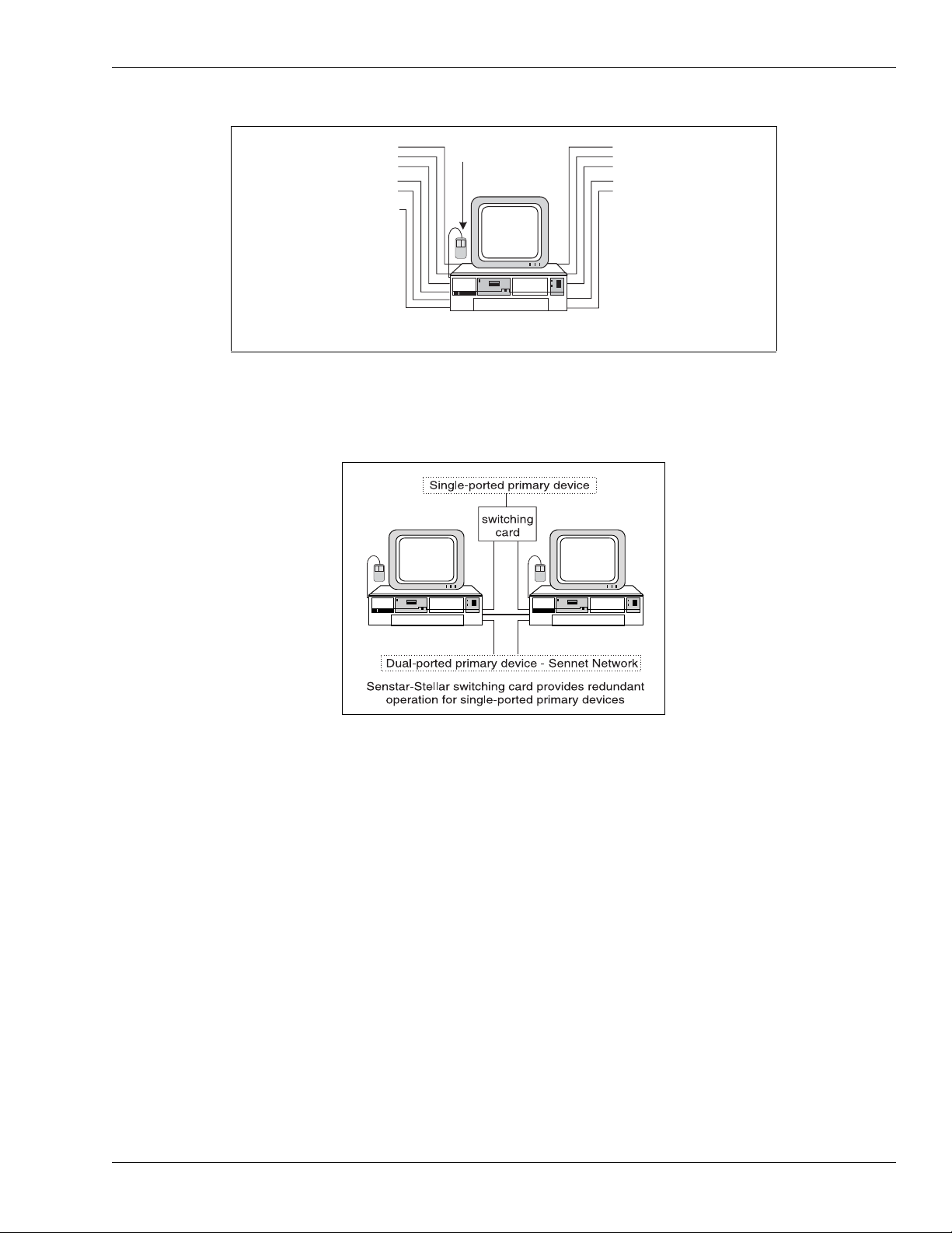
•touchscreenmonitor
•PS/2mouse-tobackup or replace touchscreen control (requires PS/2 port)
• dual-port video adapter card - for multiple monitor operation
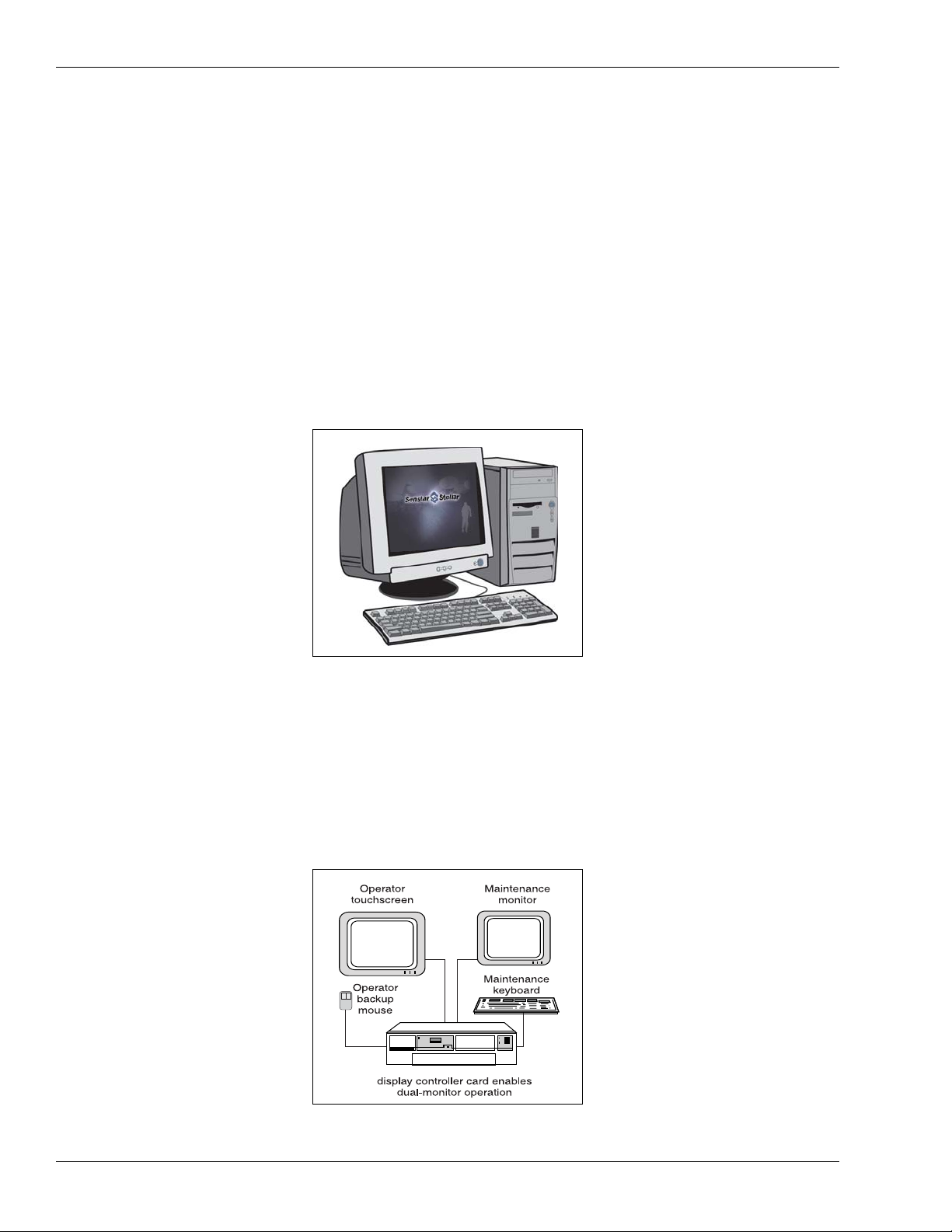
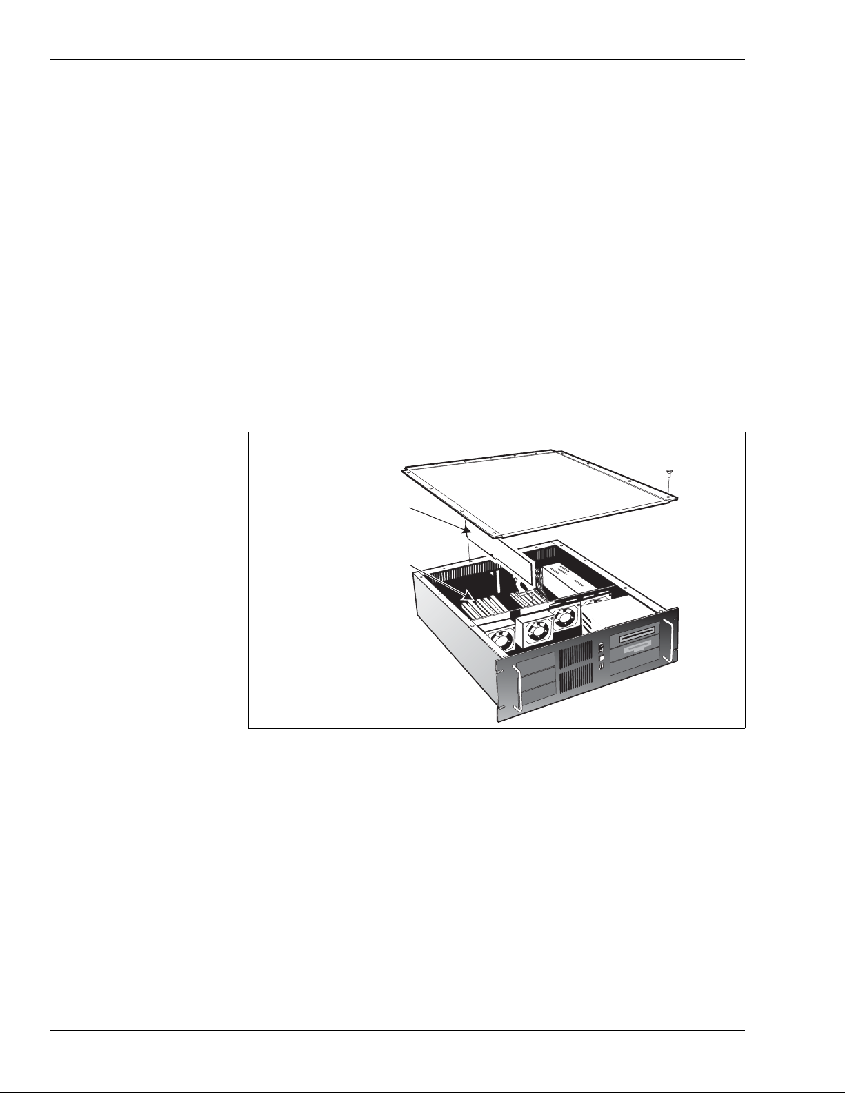
Figure 1-2 Senstar 100 CU
Figure 1-3 Dual-monitor CU
Typical hardware
Senstar100Installationguide • • • 1-5
• serial port adapter cards - for additional serial ports
• serial switching cards - to provide redundant operation for single-ported
primary devices (refer to Appendix B for additional information)
• parallel or serial printer
• second parallel or serial printer - for dedicated report printing
• one or two auxiliary printers - for system activity event logging
• network interface card, such as 10/100 Base T Ethernet card or 100 Base FX
fiber optic card - to provide high-speed communication between multiple
CUs
Figure 1-4 Additional serial ports
Figure 1-5 Switching card for redundant operation
serial expansion cards enable the connection of up to 34 primary security
devices + video switching + multi-station operation + up to 8 secondary devices
secondary device
touchscreen
primary device - Sennet Network
primary device - Sennet Network
primary device - Sennet Network
primary device - Custom Handler
primary device - Video Switcher
primary device - Sennet Network
primary device - Sennet Network
primary device - Sennet Network
secondary device - serial printer
secondary device - serial printer
secondary device
mouse
secondary device - parallel printer
Typicalhardware
1-6 • • • Senstar 100 Installation guide
• digital I/O cards - to control local devices
Integrateddevices
The following three tables list the hardware devices that are currently supported
by standard protocols, or through custom handlers/drivers. Contact
Senstar-Stellar for information about hardware that is not included in these
tables.
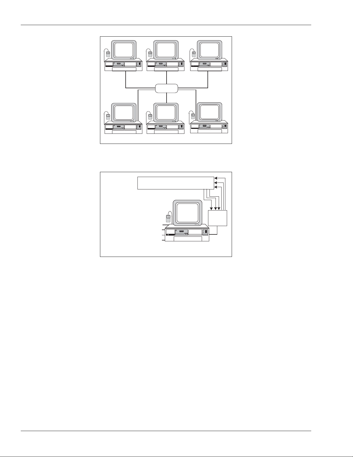
Figure 1-6 Senstar-100 network configuration
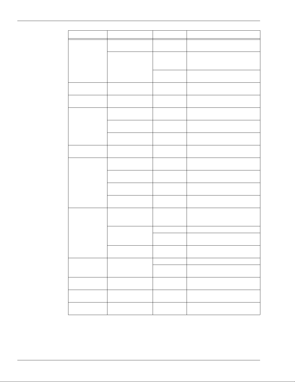
Figure 1-7 Digital I/O cards
Ethernet cards allow networking for up to 16 Senstar 100 CUs
network
hub
digital I/O cards enable the connection of local input and output devices
primary device - Video Switcher
primary device - Sennet Network
primary device - Sennet Network
secondary device - serial printer
secondary device
mouse
local I/O device, e.g., sirens, panic buttons,
lights, switches, alarm displays, etc.
secondary device
touchscreen
breakout
box

Typical hardware
Senstar100 Installationguide • • • 1 - 7
Hardware Type Manufacturer Model # Comments
CCTV Video
Switcher
American Dynamics MSS
Matrix Switching System
includes:
AD 1024 series
AD 1650B
AD 1906CPU
AD 2052WIP
AD 2150
Broadcast Video Obsolete product
COHU MPC 104
Panasonic WJ 550 Also referred to as Panasonic 500
WJ 410 Freeze-frame quad
Pelco 9500
9750/9760
Philips (Bosch) Allegiant
8300-8800 Also known as Burle Allegiant
RCA 1600/1700 Obsolete product
Sennet® Devices Senstar-Stellar
NC Network Controller
TU Transponder Unit
LTU Large Transponder Unit
RDCP Remote Display & Control Panel
SM Perimitrax Sensor Module
I-FLEX Intelli-FLEX processor
Sentrax®
Devices Senstar-Stellar
TM Transceiver Module (obsolete
product)
CM Control Module (obsolete
product)
IU Interface Unit (obsolete product)
Video Motion
Detector Senstar-Stellar DAVID® 300 Obsolete product
OEM Sensors
ECSI FOIDS Fence Sensor (via serial data link)
Fiber Sensys
FCA-185
FCA-184
FCA-182
Fence Sensor (via serial data link)
Personal Portable
Alarm (PPA)
Digilarm Via Starcom protocol
Perimeter Products
Senstar-Stellar
Flare
(ID+location)
Via Starcom protocol
Senstar-Stellar
Flash (ID only) Via Starcom protocol
Cell Call System Inter-City Video Via Starcom protocol
Marcomm Via Starcom protocol
Weather Logger Contact Senstar-Stellar for details Real time weather-logging and
weather/alarm correlation
Table 1-1 Senstar 100 supported hardware
Typicalhardware
1-8 • • • Senstar 100 Installation guide
Hardware Type Manufacturer Model # Comments
Cell Call
MicroComm DXI- Intercom
System
String Parser to CH Inputs for
Cell Call Alarms Interface
Senstar-Stellar
Output
Activation
Filter Driver
Two-Wire Cell Call
VTICS Voice Type Inmate Cell Call
System (Sennet-based)
Cell Call/Door
Control Simplex Printer String Parser Type
Interface for Data Logging
Door Control/
Fire Alarm Edwards Text String Lookup Table Parser
for Alarms Interface
Fire Alarm
Secutron Parallel Printer String Parser
Alarm Interface
Senetor Printer String Parser Alarm
Interface
Ziton ZCP2 Master and Distributed Field
Panels Alarm Interface
Fire/Riot Alarm Siemens-Cerberus MXL Printer String Parser Type
Interface for Data Logging
Alarm Data
Panels
Aritech System Printer String Parser Alarm
Interface
Scope Cabaret Printer String Parser Alarm
Interface
SUR-CARD Single Line
Receiver Distributed Alarm Panel Interface
York Building
Management System
Printer String Parser Alarm
Interface
Video Switching/
Control
NSSC
Digital Video
Capture
System
Alarm and Current Zone Output
Messages
Siemens
MATRIX Specific Serial Output Messages
Video Cross
Bar Specific Serial Output Messages
ULTRAK MAX-1000 User Definable Serial Output
Messages
Personal Portable
Alarms DigiLARM
D400/D402 Obsolete product
StarCom without Audit Interface
(obsolete product)
Personal Alarm
Locator System Perimeter Products Senstar-Stellar
PALS
Combined PPA Number and
Locator System
Fence Sensors Perimeter Products Comgard
MX-1000 FPS2-2 Sensor Integration
Mimic Panel WSA Output Messages Drive Mimic
Panel
Table 1-2 Senstar 100 supported custom equipment

Typical hardware
Senstar100 Installationguide • • • 1 - 9
Hardware Type Manufacturer Model # Comments
Local Printer Epson 9/24 pin Or equivalent
Color Printer Epson Inkjet Or equivalent
Mouse
Any Vendor
Logitech
PS/2 comp. Not USB
PS/2 & serial C7 standard (obsolete)
Microsoft PS/2 & serial Not USB
Keyboard Any vendor Not USB
Monitor Any vendor 640 x 480
Primary
Secondary
Ter tia ry
Touchscreen ELO
Tou ch Sys te ms
Smartset
Accutouch Obsolete product
Intellitouch Obsolete product
Display
Controller
Colorgraphic
Predator LT2 &
PRO Dual VGA (PCI)
Warp Obsolete product
STB Systems MVP-2 Obsolete product
MVP-2x Obsolete product
Multifunction
Card Senstar-Stellar PCI Version
Multifunction
Card Senstar-Stellar ISA version Obsolete product
Direct I/O
(Isolated Input/
Relay Output)
ICS Advent
IO1-16P 16 in, 16 out (PCI) and (ISA)
IB1-16P 16 in (PCI) and (ISA)
RB1-16P 16 relay out (PCI) and (ISA)
RB1-32P 32 relay out (PCI) and (ISA)
Serial Expansion
Comtrol
Smart Hostess 8 ISA (obsolete product)
Hostess 4 ISA (obsolete product)
Hostess i8 ISA (obsolete product)
Hostess i16 ISA (obsolete product)
RocketPort 8 PCI
RocketPort 16 PCI
Connect Tech
Dflex 4 ISA
Dflex 8 ISA
Blue Heat 4 & 8 PCI
Network
Interface Cards
Corman
ARCNET™ Obsolete product
100 Base FX
Fiber ARCNET™ Fiber optic
Any Vendor
supported by
QNX
10/100 Base T Ethernet
Table 1-3 Senstar 100 supported computer hardware and peripherals

Serial and parallelport capacity
1-10 • • • Senstar100 Installationguide
Serial and parallel port capacity
The Senstar 100 system is expandable to a maximum of 36 serial ports, to allow
you to connect devices to the system. Most primary devices are connected to the
Senstar CU via serial cable. The exception is a multi-station system which uses
standard off-the-shelf Ethernet networking components.
There is a maximum of 36 primary devices, and they are designated as follows:
• 34 ports are allocated to primary security devices.
• One port is reserved for video switching (up to 16 VS per database, one
serial port, and one primary device designation in the site database are
required for each VS).
• One port is reserved for multi-station operation (two CUs can be
connected via serial cable; two to 16 CUs can be connected via Ethernet
network). After connecting the first CU, each additional CU requires one
primary device designation in the site database. (For example, in a system
with four Senstar 100 CUs that are connected via Ethernet and one VS,
there is room for 32 security devices.)
Also, each CU allows the connection of up to eight secondary devices (serial
touchscreen, serial or PS/2 mouse, modem, serial and parallel printers, and event
input).
Portsprovided
The Multifunction card (MFC) provides two serial ports. The computer
motherboard usually provides two serial ports (COM1 and COM2) for the
connection of secondary devices, and one parallel port for a printer interface.
The PCI version MFC serial ports cannot be used to
communicate with secondary devices.
Additionalserial ports
If your total serial port requirement exceeds the standard number of ports
available, you can add one or more serial expansion cards to the system, for an
additional 4, 8, or 16 serial ports per card. Refer to Table 1-3, page 1-9 for a list of
supported expansion cards.

Senstar100 Installationguide • • • 2 - 1
2
Installing the cards
Service should be performed only by qualified personnel.
Turn OFF the power to the computer and any peripheral
components, and disconnect the power cords from the outlets
BEFORE removing the cover and working on the inside of the
computer.
The following procedures require handling static sensitive
components. To prevent damage from static electricity, always
follow proper ESD procedures when handling adapter cards
and when working inside the computer.
Refer to the manufacturers’ documentation for detailed
instructions on installing and configuring adapter cards.
Warning
Caution
Overviewofthecards
2-2 • • • Senstar 100 Installation guide
Overview of the cards
Adaptercards installationlocation
Adapter cards are installed in the computer. Each card fits into either a PCI or an
ISA expansion slot on the motherboard. The PCI slot is a 32-bit slot that provides
the wide bandwidth and high speed required by most modern computer
accessories. The ISA slot is a 16-bit expansion slot. Few modern computers
include ISA expansion slots; however, Senstar 100 still supports ISA slot adapters
for use in older computer models.
Figure 2-1 Motherboard expansion slots illustrates a typical arrangement of
expansion slots on a PC motherboard. Consult the computer motherboard
manual for detailed information.
PCI expansion slots
The PCI slot provides a 32-bit connection to a 33 MHz data bus. The PCI slot
connectors are slightly shorter than the ISA slot connectors. Generally, you can
use any available PCI slot for a PCI adapter card. Make note of the slot in which
you place each card, for external identification.
Figure 2-1 Motherboard expansion slots
expansion
slots
system board
Table of contents
Other SENSTAR Control System manuals

Popular Control System manuals by other brands

Panasonic
Panasonic CZ-256ESMC2 Operation manual

Roberts Gorden
Roberts Gorden System Control HP 120 V 1 Installation & operation

Honeywell
Honeywell Experion MX Operator's guide

Vertiv
Vertiv Liebert iCOM Installer/user guide

Muncie
Muncie MP2 Operation, service and parts manual

Elsner
Elsner WS1 Color Brief Instruction


