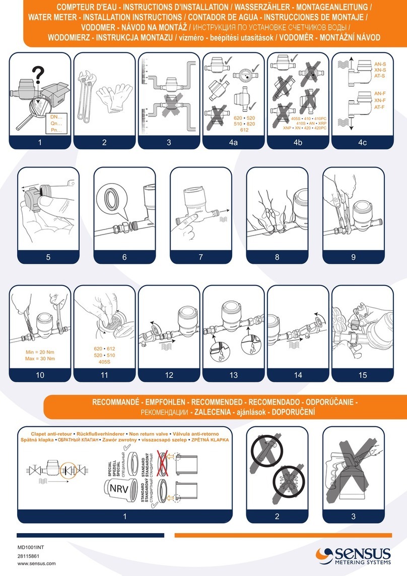
Sensus 620 User manual
Other Sensus Measuring Instrument manuals
Sensus
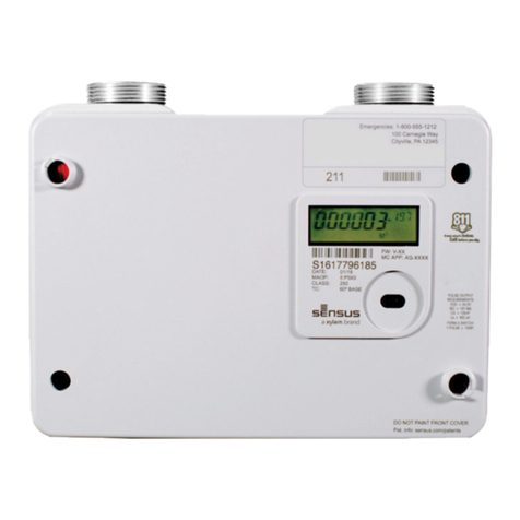
Sensus SonixIQ 250CFH User manual
Sensus
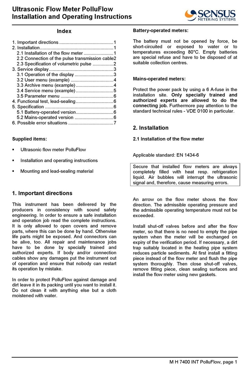
Sensus PolluFlow User manual

Sensus
Sensus MiniBus User manual

Sensus
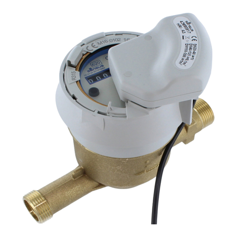
Sensus iPerl User manual
Sensus
Sensus MD 1670 Instruction Manual
Sensus
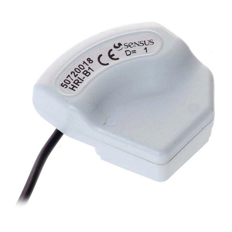
Sensus HRI User manual
Sensus
Sensus RadioRead 510 User manual
Sensus
Sensus HRI PulseUnit User manual
Sensus
Sensus OMNI C2 User manual
Sensus
Sensus iPerl User manual
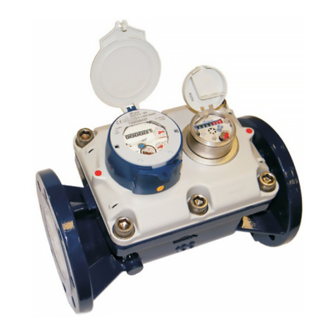
Sensus
Sensus MeiTwin 50 User manual
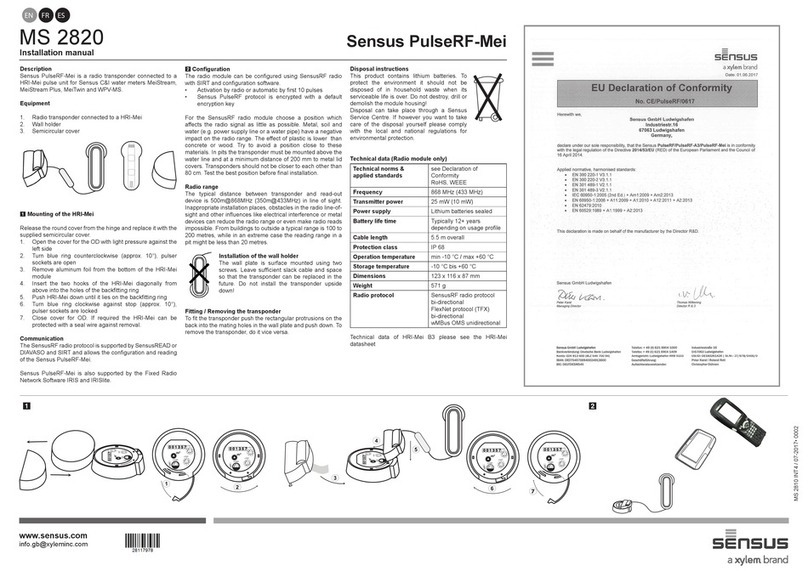
Sensus
Sensus PulseRF-Mei MS 2820 User manual
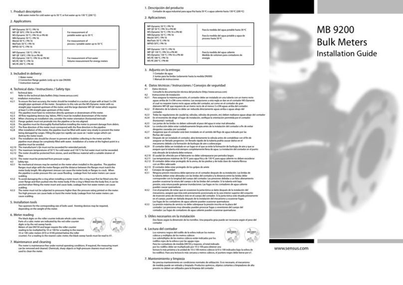
Sensus
Sensus MB 9200 User manual
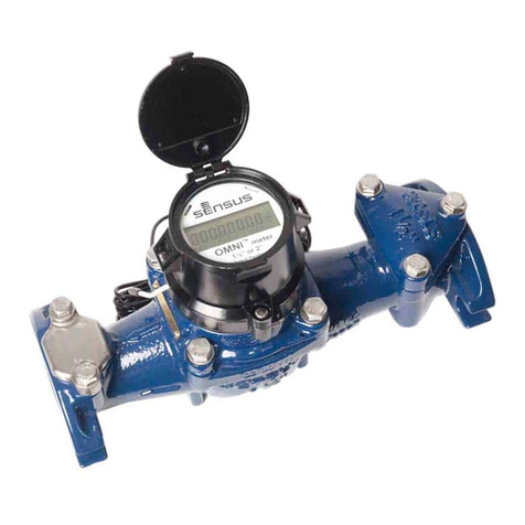
Sensus
Sensus OMNI User manual
Sensus
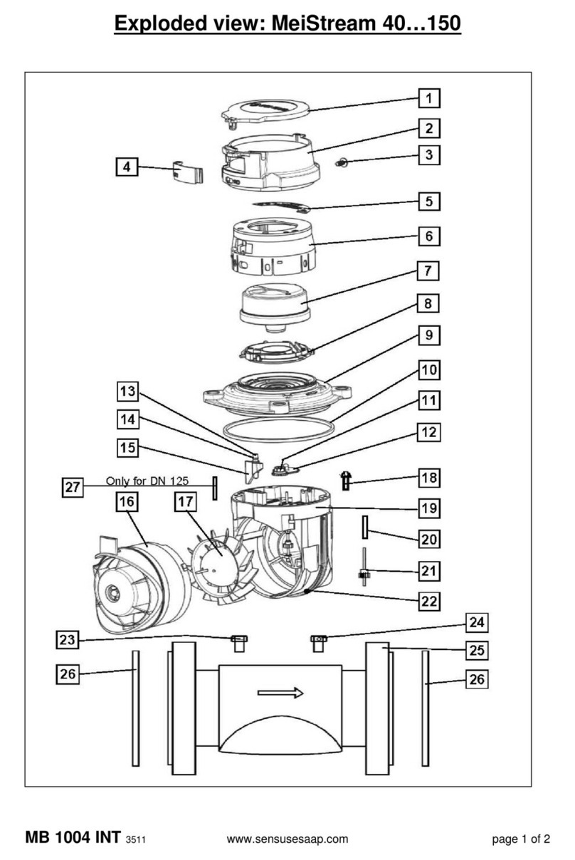
Sensus MeiStream 40 User manual
Sensus
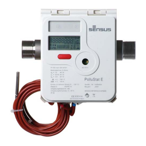
Sensus PolluStat E User manual
Sensus
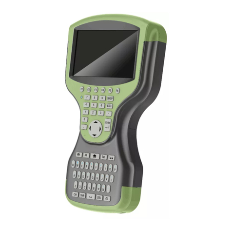
Sensus iCon APX User manual
Sensus
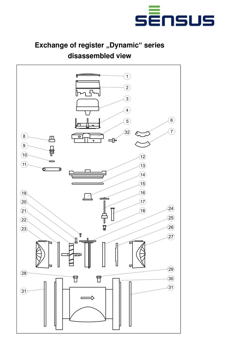
Sensus Dynamic Series User manual
Sensus
Sensus FieldLogic FL6500 Series User manual
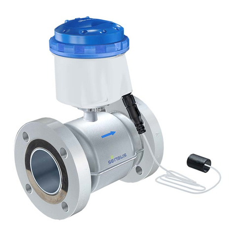
Sensus
Sensus ACCUMAG User manual
Popular Measuring Instrument manuals by other brands

Powerfix Profi
Powerfix Profi 278296 Operation and safety notes

Test Equipment Depot
Test Equipment Depot GVT-427B user manual

Fieldpiece
Fieldpiece ACH Operator's manual

FLYSURFER
FLYSURFER VIRON3 user manual

GMW
GMW TG uni 1 operating manual

Downeaster
Downeaster Wind & Weather Medallion Series instruction manual

Hanna Instruments
Hanna Instruments HI96725C instruction manual

Nokeval
Nokeval KMR260 quick guide

HOKUYO AUTOMATIC
HOKUYO AUTOMATIC UBG-05LN instruction manual

Fluke
Fluke 96000 Series Operator's manual

Test Products International
Test Products International SP565 user manual

General Sleep
General Sleep Zmachine Insight+ DT-200 Service manual


