Sentec tcPCO2 User manual
Instruction Manual
For the Digital Monitoring System
(Software version SMB SW-V08.02; MPB SW-V06.02)
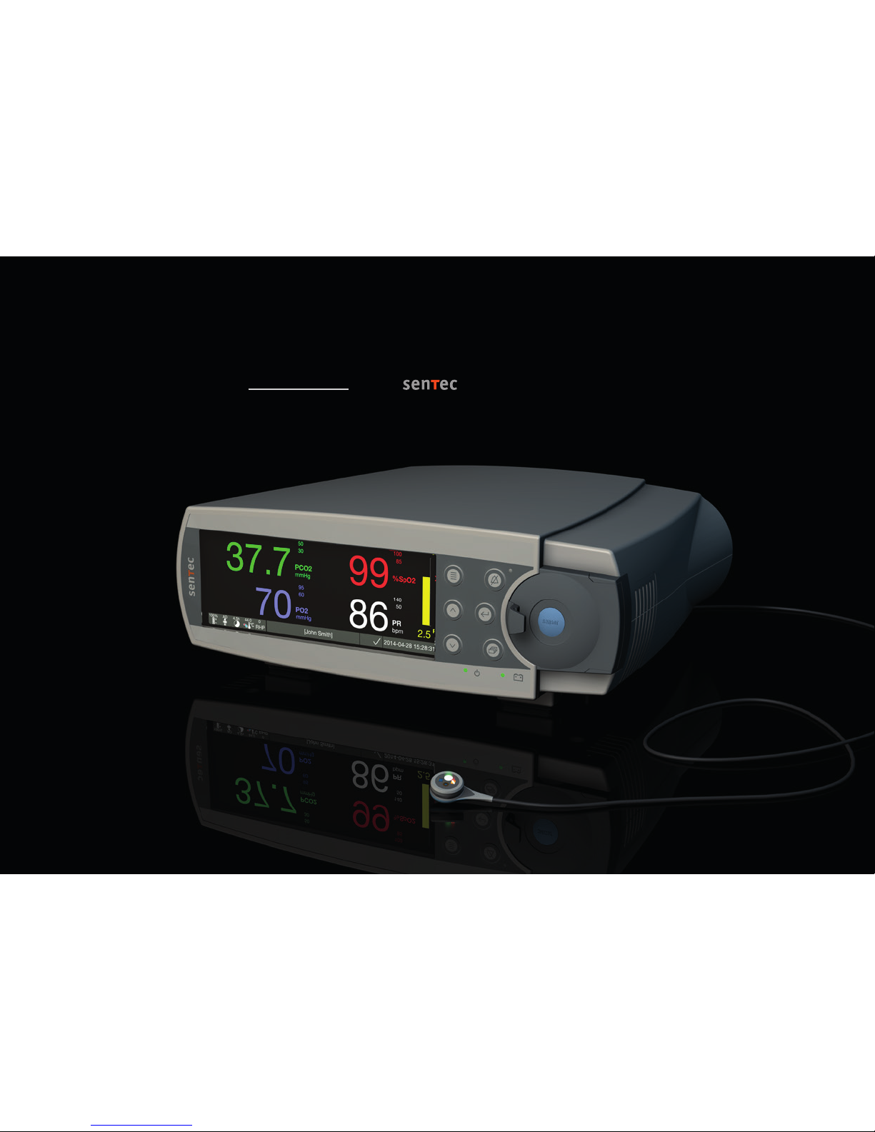
SenTec Digital Monitoring System
Noninvasive Ventilation and Oxygenation Monitoring
[John Smith]
[Sarah Miller]
19 20 21 22 23 24
15 16 17 18
12 sec
100
70
75
25
- 15 min 0 min
- 15 min 0 min
0 min
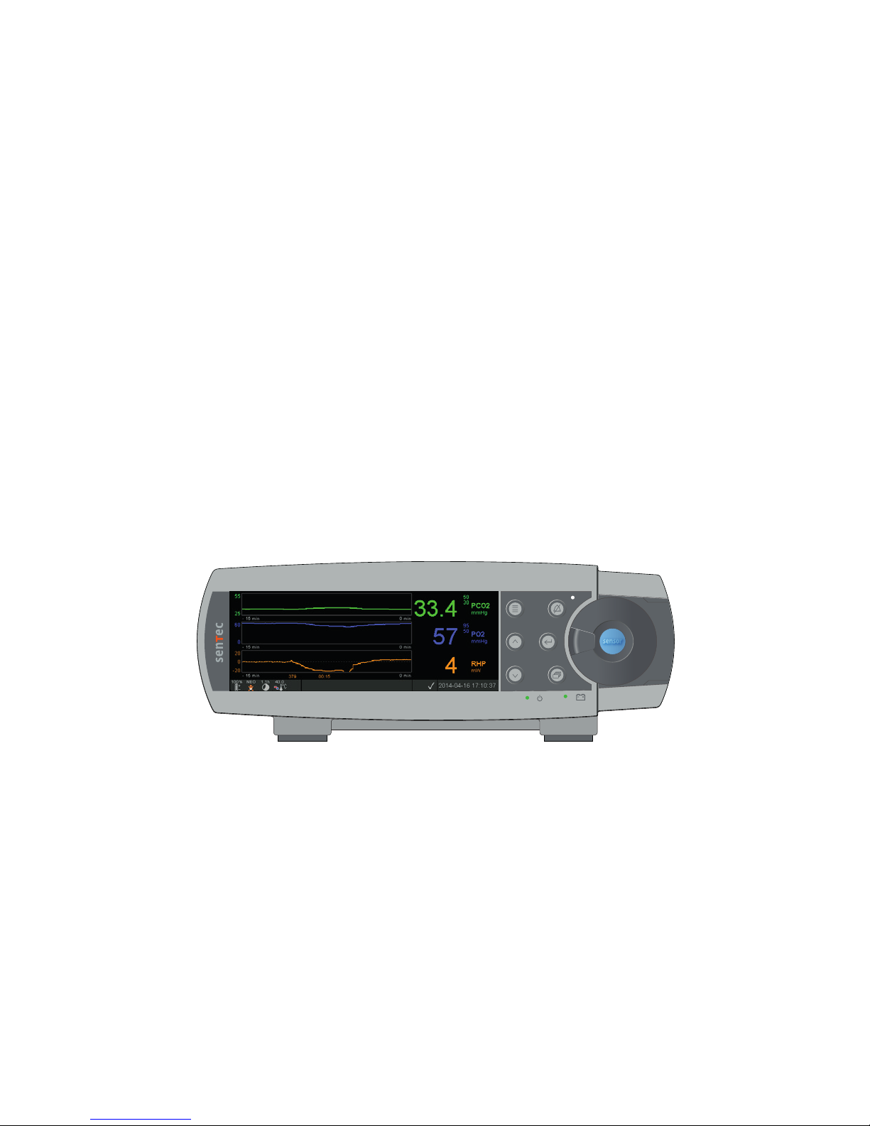
39.4
50
30 PCO2
mmHg
84140
50 PR
bpm
96
100
85 %SpO2
2.0 PI
100%
+
-
7.7h
AD
°C
42.0
RHP
0
[John Smith] 2014-04-28 15:28:31
1 2 3 4
5
6
7
8101213
14
11 9
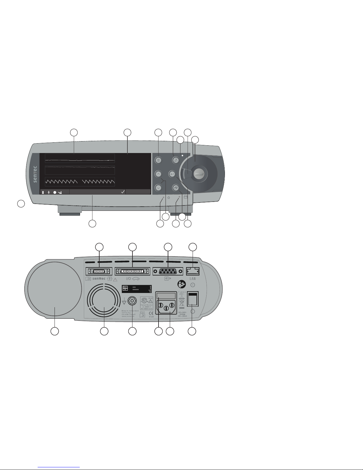
1Trend Display Area
2Numerical Display Area
3Menu/Previous Level Button
4AUDIO PAUSED/OFF Button
5AUDIO PAUSED/OFF Indicator (yellow LED)
6Door Handle
7Docking Station Door (colored dot in center
of door indicates the SDM’s PO2activation
status: blue if activated, orange otherwise)
8Enter Button
9Display Button
10 AC Power/Battery Indicator
(green/yellow LED)
11 UP/DOWN Buttons
12 ON/OFF Indicator (green LED)
13 Status Bar
14 Speaker (on the side)
15 Sensor Connection Port
16 Multipurpose l/O-Port
(Nurse Call & Analog Output)
17 Serial Data Port (RS-232)
18 Network Port (LAN)
19 Gas Bottle Slot
20 Fan
21 Equipotential Terminal Connector (ground)
22 Fuse Holder
23 AC Power Connector
24 ON/OFF Switch

C
L
A
S
S
I
F
I
E
D
UL
C U
S
R
Warranty
The manufacturer warrants to the initial purchaser that each new component of the SenTec Digital Monitoring System will be free from defects in
workmanship and materials. The manufacturer’s sole obligation under this warranty is to at its own choice repair or replace any component – for
which the manufacturer acknowledges the warranty cover – with a replacement component.
Warranty Exclusions and System Performance
SenTec AG can neither guarantee or verify instrument performance characteristics nor accept warranty claims or product liability claims if the
recommended procedures are not carried out, if the product has been subject to misuse, neglect or accident, if the product has been damaged
by extraneous causes, if accessories other than those recommended by SenTec AG are used, if the warranty seal on the lower side of the monitor
is broken, or if instrument repairs are not carried out by SenTec authorized service personnel.
CAUTION: Federal law (U.S.) restricts this device to sale by or on the order of a physician.
Patents/Trademarks/Copyright
International Industrial Design No. DM/054179, Japanese Design No. 1137696, U.S. Design Patent No. D483488. Canadian Patent No. 2466105,
European Patent No. 1335666, German Patent No. 50111822.5-08, Spanish Patent No. 2278818, Hongkong Patent No. HK1059553, U.S. Patent
No. 6760610. Chinese Patent No. ZL02829715.6, European Patent No. 1535055, German Patent No. 50213115.2, Spanish Patent No. 2316584,
Indian Patent No. 201300, Japanese Patent No. 4344691, U.S. Patent No. 7862698. SenTec™, V-Sign™, OxiVenTTM, V-STATS™, V-CareNeT™,
V-Check™, Staysite™, Illuminate Ventilation™ and Advancing Noninvasive Patient Monitoring™ are trademarks of SenTec AG / © 2018 SenTec AG.
All rights reserved. The contents of this document may not be reproduced in any form or communicated to any third party without the prior
written consent of SenTec AG. While every effort is made to ensure the correctness of the information provided in this document, SenTec AG
assumes no responsibility for errors or omissions. This document is subject to change without notice.
Patient Monitor
IN ACCORDANCE WITH IEC 60601-1; ANSI/AAMI ES60601-1; CAN/CSA C22.2 No. 60601-1,
IEC 60601-1-2, IEC 60601-2-23, ISO 80601-2-61
Manufacturer: SenTec AG, Ringstrasse 39, CH-4106 Therwil, Switzerland,
www.sentec.com

Page 3.Contents
Contents
Intended Use, Principles of Operation and Limitations .............................................................. 5
Intended Use of the SenTec Digital Monitoring System (SDMS) ...................................................................................... 5
Transcutaneous PCO2and PO2..........................................................................................................................................5
Pulse Oximetry .................................................................................................................................................................7
SenTec TC Sensors ...........................................................................................................................................................9
The SenTec Digital Monitoring System (SDMS) ........................................................................ 10
Setting up the SDMS ................................................................................................................. 12
Connect SDM to AC Power ............................................................................................................................................. 12
Battery Operation of the SDM ........................................................................................................................................ 12
Turning on the SDM........................................................................................................................................................ 12
Installation of the Gas Bottle (Service Gas-0812) .......................................................................................................... 13
Connection/Disconnection of Digital Sensor Adapter Cable ........................................................................................... 13
Connection of a SenTec TC Sensor................................................................................................................................. 14
Sensor Check, Sensor Calibration/Storage and Membrane Change ......................................... 15
Checking a SenTec TC Sensor ........................................................................................................................................ 15
Sensor Calibration and Storage ...................................................................................................................................... 16
Changing the Sensor Membrane .................................................................................................................................... 17
Patient Monitoring with the SDMS............................................................................................ 20
Selection of Patient Type, Measurement Site, and Sensor Attachment Accessory ........................................................ 20
Check SDM Settings and System Readiness................................................................................................................... 22
Sensor Application Using a Multi-Site Attachment Ring/Easy......................................................................................... 24
Sensor Application Using an Ear Clip.............................................................................................................................. 27
Patient Monitoring .......................................................................................................................................................... 29
Sensor Removal with Multi-Site Attachment Ring/Easy.................................................................................................. 38
Sensor Removal with Ear Clip......................................................................................................................................... 40

Controls, Indicators and Alarms................................................................................................ 42
Controls (Buttons) .......................................................................................................................................................... 42
LED Indicators ................................................................................................................................................................ 45
Auditory Indicators/Signals............................................................................................................................................. 45
Alarms ............................................................................................................................................................................ 46
Status Bar with Status Icons and Status Messages........................................................................................................ 48
Maintenance of the SDMS ......................................................................................................... 50
Routine Checks............................................................................................................................................................... 50
Service............................................................................................................................................................................ 51
Specifications of tcPCO2, tcPO2and Pulse Oximetry ................................................................ 52
Specifications of tcPCO2and tcPO2................................................................................................................................. 52
Specifications of Pulse Oximetry..................................................................................................................................... 53
Glossary of Symbols .................................................................................................................. 54

Page 5.Intended Use, Principles of Operation and Limitations
Intended Use of the SenTec Digital
Monitoring System (SDMS)
The SenTec Digital Monitoring System (SDMS) – consisting
of the SenTec Digital Monitor (SDM), sensors and accessories
(p. 10) – is indicated for continuous, noninvasive monitoring
of carbon dioxide tension and oxygen tension as well as oxygen
saturation and pulse rate in adult and pediatric patients. In
neonatal patients the SDMS is indicated for carbon dioxide and
oxygen tension monitoring only. Oxygen tension monitoring is
contraindicated for patients under gas anesthesia.
The SDMS is indicated for use in clinical and non-clinical
settings such as hospitals, hospital-type facilities, intra-hospital
transport environments, clinics, physician offices, ambulatory
surgery centers and – if under clinical supervision – home
environments. The SDMS is for prescription use only.
Note: The above phrasing corresponds to an abbreviated
version of the SDMS’ Intended Use. Please refer to the current
issue of the Technical Manual for the SDM (HB-005752) for the
full phrasing of the SDMS’ Intended Use.
Intended Use, Principles of Operation and Limitations
Transcutaneous PCO2and PO2
Principles of Operations of tcPCO2and tcPO2
Carbon dioxide (CO2) and Oxygen (O2) are gases that readily
diffuse through body and skin tissue and, therefore, can be
measured by an adequate noninvasive sensor being applied at
the skin surface. If the skin tissue beneath the sensor site is
warmed up to a constant temperature local capillary blood flow
increases, metabolism stabilizes, gas diffusion improves and,
hence, reproducibility and accuracy of CO2/O2measurements
at the skin surface improves.
CO2tensions measured at the skin surface (PcCO2) are usually
consistently higher than arterial PCO2 values (PaCO2) in patients
of all ages. It is therefore possible to estimate PaCO2from
the measured PcCO2using an adequate algorithm. TcPCO2
designates an estimate of PaCO2calculated from the measured
PcCO2with an algorithm developed by J.W. Severinghaus.
The ‘Severinghaus Equation’ first corrects PcCO2measured at
the sensor temperature (T) to 37 °C by using an anaerobic
temperature factor (A) and then subtracts an estimate of the
local ‘Metabolic Offset’ (M).
Note: Hence, the tcPCO2values displayed by the SDM are
corrected/normalized to 37 °C and provide an estimate of
PaCO2at 37 °C. On the SDM and throughout this manual
(unless explicitly stated otherwise) ‘tcPCO2’ is displayed/
labeled as ‘PCO2’.
In newborns PO2measured at the skin surface (PcO2) correlates
with arterial PO2(PaO2) almost in a one to one relationship at
a sensor temperature of 43 to 44 °C, whereby the accuracy
of PcO2compared to PaO2is best up to PaO2of 80 mmHg
(10.67 kPa), above which it increasingly tends to read lower
than PaO2(especially in adults). As target PaO2levels in
newborns are usually below 90 mmHg (12 kPa), a correction
of PcO2values measured at a sensor temperature of 43 to
44 °C is normally not necessary. TcPO2designates an estimate
of PaO2and corresponds to the measured PcO2.
Note: On the SDM and throughout this manual (unless
explicitly stated otherwise) ‘tcPO2’ is displayed/labeled as ‘PO2’.
Good to know!
Warming the skin tissue beneath the sensor to a constant
temperature improves accuracy as it a) increases capillary
blood flow/induces local arterialization, b) stabilizes
metabolism, and c) improves gas diffusion through skin
tissue. With increasing sensor temperature the application
duration (‘Site Time’) must be evaluated carefully and
adjusted accordingly to reduce the risk of burns. Special
attention must be given to patients with sensitive skin
at the sensor site (e.g. preterm or geriatric patients, burn
victims, patients with skin diseases) and/or very low skin
tissue perfusion beneath the sensor site (e.g. hypothermic
patients, patients with vasoconstrictions, low blood pressure,
or circulatory centralization (shock)).
Please refer to Technical Manual for the SDM (HB-005752)
and the references cited therein for additional information on
transcutaneous blood gas monitoring.
Limitations of tcPCO2and tcPO2
The following clinical situations or factors may limit the
correlation between transcutaneous and arterial blood gas
tensions:
• Hypo-perfused skin tissue beneath the sensor site due
to low cardiac index, circulatory centralization (shock),
hypothermia (e.g. during surgery), use of vasoactive drugs,
arterial occlusive diseases, mechanical pressure exercised
on measurement site, or inadequate (too low) sensor
temperature.
• Arterio-venous shunts, e.g. ductus arteriosus (PO2specific).
• Hyperoxemia (PaO2> 100 mmHg (13.3 kPa)) (PO2specific).
• Inadequate measurement site (placement over large
superficial veins, on areas with skin edema (e.g. oedema
neonatorum), skin breakdown, and other skin anomalies).
• Improper sensor application resulting in an inadequate, not
hermetically sealed contact between the sensor surface and
the patient’s skin causing the CO2and O2gases diffusing out
of the skin to intermix with ambient air.
• Exposure of the sensor to high ambient light levels (PO2
specific).
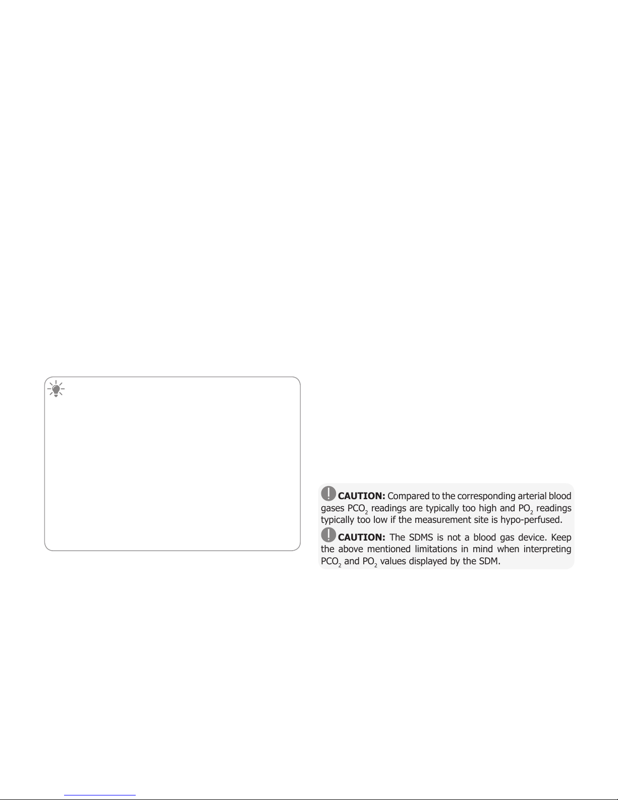
CAUTION: Compared to the corresponding arterial blood
gases PCO2readings are typically too high and PO2readings
typically too low if the measurement site is hypo-perfused.
CAUTION: The SDMS is not a blood gas device. Keep
the above mentioned limitations in mind when interpreting
PCO2and PO2values displayed by the SDM.

Page 7.Intended Use, Principles of Operation and Limitations
When comparing PCO2/PO2values displayed by the SDM with
PaCO2/PaO2values obtained from arterial blood gas (ABG)
analysis, pay attention to the following points:
• Carefully draw and handle blood samples.
• Blood sampling should be performed in steady state
conditions.
• The PaCO2/PaO2value obtained from ABG analysis should be
compared to the SDM’s PCO2/PO2reading at the time of blood
sampling.
• In patients with functional shunts, the sensor application site
and the arterial sampling site should be on the same side of
the shunt.
• If the menu-parameter ‘Severinghaus Correction Mode’
is set to ‘Auto’, the PCO2values displayed by the SDM are
automatically corrected to 37 °C (regardless of the patient’s
core temperature). When performing the ABG analysis, be
sure to properly enter the patient’s core temperature into the
blood gas analyzer. Use the blood gas analyzer’s ‘37 °C-PaCO2’
value to compare with the SDM’s PCO2value.
• Verify proper operation of the blood gas analyzer. Periodically
compare the blood gas analyzer’s barometric pressure against
a known calibrated reference barometer.
Pulse Oximetry
Principles of Operations of Pulse Oximetry
The SDMS uses pulse oximetry to measure functional oxygen
saturation (SpO2) and pulse rate (PR). Pulse oximetry
is based on two principles: firstly, oxyhemoglobin and
deoxyhemoglobin differ in their absorption of red and infrared
light (spectrophotometry) and secondly, the volume of arterial
blood in tissue (and hence, light absorption by that blood)
changes during the pulse (plethysmography).
Pulse oximeter sensors pass red and infrared light into a
pulsating arteriolar vascular bed and measure changes in light
absorption during the pulsatile cycle. Red and infrared low-
voltage light-emitting diodes (LED) serve as light sources and
a photodiode serves as photodetector. The software of a pulse
oximeter uses the ratio of absorbed red to infrared light to
calculate SpO2.
Pulse oximeters use the pulsatile nature of arterial blood flow
to differentiate the oxygen saturation of hemoglobin in arterial
blood from the one in venous blood or tissue. During systole,
a new pulse of arterial blood enters the vascular bed: blood
volume and light absorption increase. During diastole, blood
volume and light absorption decrease. By focusing on the
pulsatile light signals, effects of nonpulsatile absorbers such as
tissue, bone and venous blood are eliminated.

Note: The SDMS measures and displays functional oxygen
saturation: the amount of oxygenated hemoglobin expressed
as a percentage of the hemoglobin that can transport oxygen.
The SDMS does not measure fractional saturation: oxygenated
hemoglobin expressed as a percentage of all hemoglobin, in-
cluding dysfunctional hemoglobin such as carboxyhemoglobin
or methemoglobin.
Good to know!
Oxygen saturation measurement techniques – including pulse
oximetry – are not able to detect hyperoxemia.
Due to the S-shape of the oxyhemoglobin dissociation curve
(ODC) SpO2alone cannot reliably detect hypoventilation in
patients being administered with supplemental oxygen.
Limitations of Pulse Oximetry
The following clinical situations or factors may limit the
correlation between functional oxygen saturation (SpO2) and
arterial oxygen saturation (SaO2) and may cause the loss of
the pulse signal:
• dysfunctional hemoglobins (COHb, MetHb)
• anemia
• intravascular dyes, such as indocyanine green or methylene
blue
• low perfusion at the measurement site (e.g. caused by inflated
blood pressure cuff, severe hypotension, vasoconstriction in
response to hypothermia, medication, or a spell of Rynaud’s
syndrome)
• venous pulsations (e.g. due to use of the forehead, cheek
or earlobe as a measurement site on a patient in steep
Trendelenburg position)
• certain cardiovascular pathologies
• skin pigmentation
• externally applied coloring agents
(e.g. nail polish, dye, pigmented cream)
• prolonged and/or excessive patient movement
• exposure of the sensor to high ambient light levels
• defibrillation

Page 9.Intended Use, Principles of Operation and Limitations
SenTec TC Sensors
SenTec TC Sensors provide superior performance, are robust,
reliable and require comparatively low maintenance. They
combine within a patented digital sensor design the optical
components needed for 2-wavelength, reflectance pulse
oximetry with the components needed to measure PCO2and –
in case of the OxiVenT™ Sensor only – PO2.
PO2(OxiVenT™ Sensor) is measured with dynamic fluorescence
quenching, an oxygen sensing technology measuring the
oxygen molecules present in the vicinity of a fluorescent dye
being immobilized in a thin carrying layer incorporated within
the sensor surface.
The PCO2measurement of SenTec TC Sensors (V-Sign™
Sensor 2, OxiVenT™ Sensor) is based on a Stow-Severinghaus
type PCO2sensor, i.e. a thin electrolyte layer is confined to
the sensor surface with a hydrophobic, CO2and O2permeable
membrane. Membrane and electrolyte must be exchanged
every 28 to 42 days. With SenTec’s patented Membrane
Changer the membrane and electrolyte can be changed
with the ease of 4 identical Press-and-Turn steps in a highly
reproducible manner (p. 17).
Calibration of the PCO2segment of SenTec TC Sensors is
recommended every 6 to 12 hours and mandatory every 12 to
16 hours (p. 16). The PO2measurement of the OxiVenT™
Sensor is virtually drift free and, hence, calibration free.
Nevertheless, the SDM, as a precaution, calibrates PO2during
each mandatory calibration and subsequently approximately
once every 24 hours during one of the anyways ongoing PCO2
calibrations.
To achieve local arterialization of the skin tissue at the
measurement site, SenTec TC Sensors are operated at a
constant sensor temperature of typically 41 °C in neonatal and
42 °C in adult/pediatric patients if PO2is disabled and – if PO2
is enabled – of typically 43 °C in neonatal and 44 °C in adult/
pediatric patients, respectively. Controls of sensor temperature
and application duration are designed to meet all applicable
standards. To guarantee safe operation, SenTec TC Sensors
reliably supervise the sensor temperature with two independent
circuits. Additionally, the SDM firmware redundantly controls
the temperature of the connected sensor.

The SenTec Digital Monitoring System (SDMS)
The SenTec Digital Monitoring System (SDMS) comprises the
following main components:
SenTec Digital Monitor (SDM)
Note: SDMs with firmware version SMB SW-V08.00/MPB SW-
V06.00 or newer are available in a software-configuration
without activated PO2-option (SDM) and in a configuration with
activated PO2-option (SDM-PO2). The respective configuration
is indicated on the SDM’s ‘Power On Self Test’ Screen and
on the second page of the menu ‘System Information’.
Furthermore, the colored dot in the center of a SDM’s Docking
Station Door 7is orange, if PO2is not activated, and blue, if
PO2is activated.
V-Sign™ Sensor 2 (for PCO2, SpO2/PR monitoring) or
OxiVenT™ Sensor (for PCO2, PO2, SpO2/PR monitoring)
Note: Throughout this manual the notion ‘SenTec TC Sensor’
refers to SenTec sensors providing transcutaneous blood gas
measurements (i.e. to the V-Sign™ Sensor 2 and the OxiVenT™
Sensor).
Digital Sensor Adapter Cable (to connect a SenTec TC Sensor
to SDM)
Ear Clip and Multi-Site Attachment Rings (to attach SenTec
TC Sensors to patients)
Staysite™ Adhesive (to improve attachment of Multi-Site
Attachment Rings, e.g. in high humidity environments, for patients
who perspire profusely and/or in challenging patient motion
conditions).
Contact Gel (contact liquid for the application of SenTec TC
Sensors)
Service Gas (to calibrate SenTec TC Sensors)
Membrane Changer (to change membrane and electrolyte
of SenTec TC Sensors)
V-STATS™ (PC based Trend Data Download/Analysis, Remote
Monitoring, and Configuration Software for SenTec Digital
Monitors)
SDMS Quick Reference Guide and SDMS Instruction
Manual (the present document)
SDMS Manual CD (with the exception of the ‘Service and
Repair Manual for the SDMS’ all manuals and Directions for
Use being related to the SDMS are provided on the Manual CD)
Note: The components listed above do not necessarily
correspond to the scope of delivery. A complete list of available
products including disposables and accessories is provided at
www.sentec.com/products.
Page 11 .The SenTec Digital Monitoring System (SDMS)
Additional information on SenTec TC Sensors, the Ear Clip,
the Multi-Site Attachment Rings, the Staysite™ Adhesive,
the Membrane Changer, and the Membrane Changer Inserts
is provided in the respective Directions for Use. Detailed
information on the SenTec Digital Monitor is provided in the
Technical Manual for the SDM (HB-005752). Information on
maintenance, service and repair procedures that do not require
opening the cover of the SDM as well as on maintenance and
service procedures for SenTec TC Sensors are provided in the
SDMS Service Manual (HB-005615).
To ensure proper operation of the SDMS, precisely follow the
instructions provided in this Instruction Manual step by step.
WARNING: The instructions given in the SDMS Quick
Reference Guide, the SDMS Instruction Manual, the Technical
Manual for the SDM, and on the SDMS Manual CD must be
followed in order to ensure proper instrument performance
and to avoid electrical hazards.
Note: Statements in this manual are only applicable for SDMs
with the software version indicated on the cover page.
Note: The SDMS Quick Reference Guide, the SDMS
Instruction Manual and various other manuals are
available for online viewing at www.sentec.com/ifu.
Note: SDMS related tutorials are available for online
viewing at www.sentec.com/tv.

Setting up the SDMS
Connect SDM to AC Power
Plug the female connector of the power
cord into the AC power connector on the
rear of the monitor 23 .
Plug the male connector of the power
cord into a properly grounded AC
power outlet.
Note: The SDM will automatically
adapt to the applicable local voltage:
100 - 240V~ (50/60Hz).
Verify that the AC power/battery indicator 10 is lit. If the AC
power/battery indicator is not lit, check the power cord, fuses,
and the AC power outlet.
Battery Operation of the SDM
The SDM is equipped with a rechargeable internal Li-Ion
battery that can be used to power the monitor during transport
or when AC power is not available. The Status Icon ‘Battery’
(p. 48) indicates the remaining battery charge (%).
Good to know!
When using an SDM with a LED backlight display, a new, fully
charged battery will provide up to 10 hours of monitoring
time if Sleep Mode=OFF or Auto, and up to 12 hours of
monitoring time if Sleep Mode=ON. It takes approximately
7 hours to fully charge a drained battery.
The AC Power/Battery Indicator 10 provides information on
the charging status of the battery:
Green: SDM connected to AC power, battery fully charged
Yellow: SDM connected to AC power, battery charging
LED OFF: SDM not connected to AC power (i.e. powered by
internal battery)
Turning on the SDM
Turn on the SDM by pushing the ON/OFF Switch on the rear
panel 24 . The SDM will automatically perform a ‘Power On
Self Test’ (POST). Check the date/time settings of the SDM and
adjust if necessary.
Note: If the POST fails, discontinue use of the SDM and contact
qualified service personnel or your local SenTec representative.
Refer to the Technical Manual for the SDM (HB-005752) for a
detailed description of the POST.
ON/OFF
switch
Page 13 .Setting up the SDMS
Installation of the Gas Bottle
(Service Gas-0812)
The gas bottle slot is located on the rear of the SDM 19 .
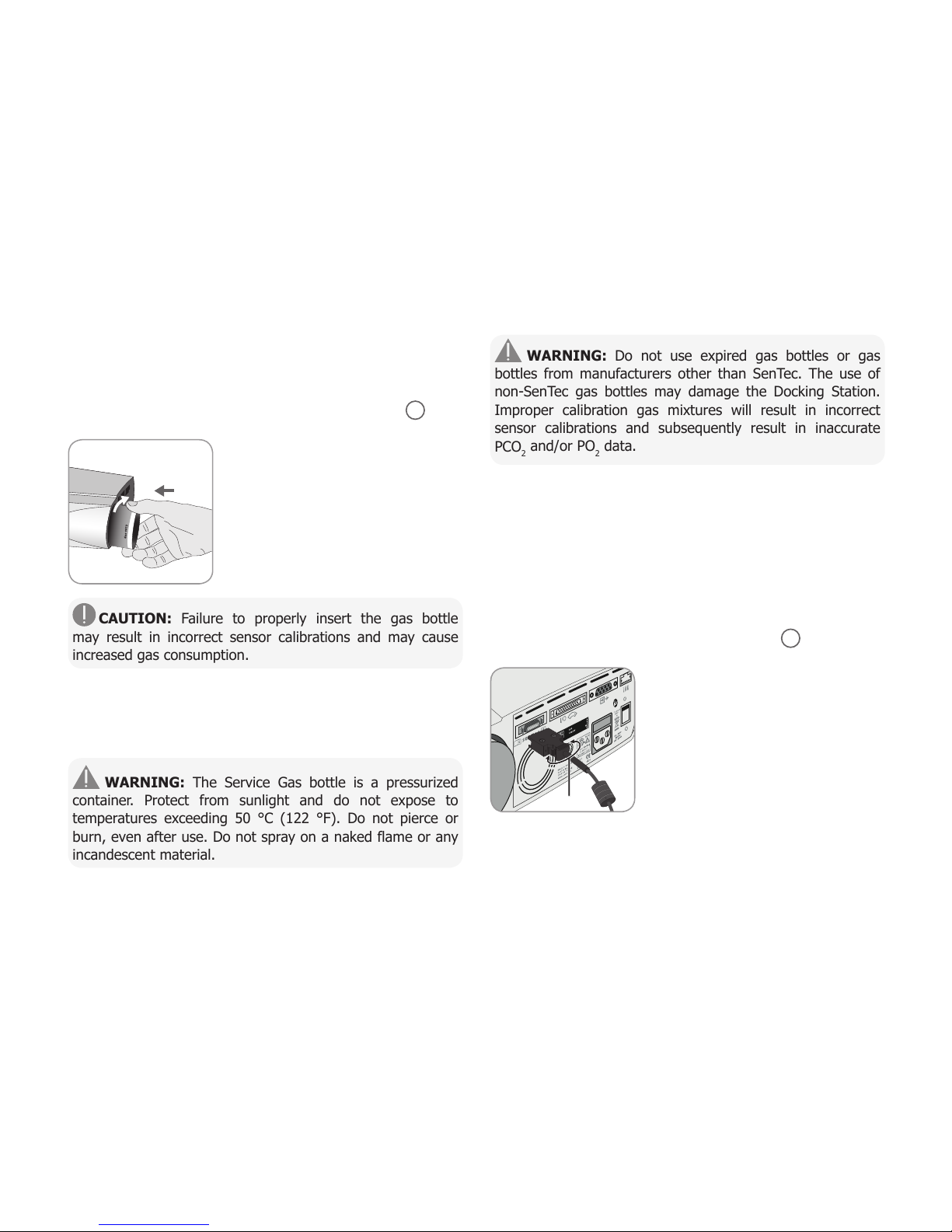
Remove the old gas bottle by turning
it counter-clockwise.
Insert the new gas bottle by turning
it clockwise approx. 4.5 turns and
thoroughly tighten it (without applying
undue force).
CAUTION: Failure to properly insert the gas bottle
may result in incorrect sensor calibrations and may cause
increased gas consumption.
The Status Icon ‘Gas’ (p. 48) indicates the remaining capacity
of the gas bottle in %. It is only displayed if a SenTec TC
Sensor is connected to the SDM and is in the Docking Station.
WARNING: The Service Gas bottle is a pressurized
container. Protect from sunlight and do not expose to
temperatures exceeding 50 °C (122 °F). Do not pierce or
burn, even after use. Do not spray on a naked flame or any
incandescent material.
WARNING: Do not use expired gas bottles or gas
bottles from manufacturers other than SenTec. The use of
non-SenTec gas bottles may damage the Docking Station.
Improper calibration gas mixtures will result in incorrect
sensor calibrations and subsequently result in inaccurate
PCO2and/or PO2data.
Dispose of empty gas bottles according to local waste disposal
regulations for aluminium containers.
Connection/Disconnection of Digital
Sensor Adapter Cable
Connect the Digital Sensor Adapter Cable to the SDM. The con-
nection is properly established when both clamps of the plug
snap into place in the sensor connection port 15 .
Disconnect the cable from the SDM
by pressing the two latches on the
black plug to release the clamps (see
picture) and pull to remove the cable.
Press

Connection of a SenTec TC Sensor
Take a SenTec TC Sensor (V-Sign™ Sensor 2 or OxiVenT™
Sensor).
Important: For PO2monitoring you must use an OxiVenT™
Sensor and an SDM with activated PO2-option.
Check the condition of the sensor membrane and the integrity
of the sensor (p. 15). Change the membrane if necessary
(p. 17). Do not use the sensor if any problems are noted.
Once sensor check/inspection of its membrane are completed
successfully, connect the SenTec TC Sensor to the Digital
Sensor Adapter Cable.
Thereafter, the SDM usually will display the message ‘Calibrate
sensor’ (for exceptions see description of the feature SMART
CALMEM, p. 17).
Insert the sensor into the Docking Station for sensor calibration
(p. 16).
If the sensor’s ‘Membrane Change Interval’ has elapsed
(this usually applies to new sensors), the SDM will trigger
the message ‘Change sensor membrane’ upon insertion of
the sensor into the Docking Station. In this case, you must
change the sensor membrane (p. 17) before the SDM starts
calibrating the sensor.
Note: If you have changed the sensor membrane just before
connecting the sensor to the SDM, it won’t be necessary
to change it once again. In this case, simply confirm the
membrane change on the monitor (menu ‘Membrane Change’ -
only accessible if the sensor is outside the Docking Station).
Checking a SenTec TC Sensor
Check the condition of the sensor membrane and the integrity
of the sensor before and after each use and after changing the
membrane (p. 17)!
Ensure that the sensor is clean before visually checking it. If
necessary, carefully wipe off any residue from the sensor’s
surface (including membrane, housing and cable) with 70%
isopropanol or another approved cleaning agent (refer to
sensor’s Directions for Use).
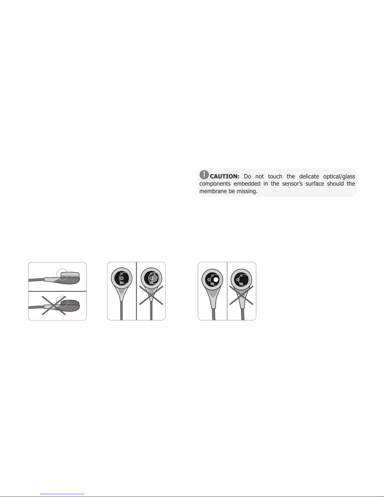
a) Change the sensor membrane if it is damaged or missing,
has a loose fit, or if there is trapped air or dry electrolyte under
the membrane.
Page 15 .Sensor Check, Sensor Calibration/Storage and Membrane Change
CAUTION: Do not touch the delicate optical/glass
components embedded in the sensor’s surface should the
membrane be missing.
b) Do not use the sensor if there is any visible damage to
the sensor housing or cable, if the color of the ring around the
glass electrode has a metallic luster (should be brown), or if the
sensor’s red LED does not light when the sensor is connected
to the SDM. Instead, contact qualified service personnel or
your local SenTec representative regarding continued use or
replacement of the sensor.
c) When operating with an OxiVenT™
Sensor, do not use the sensor if
the off-centered, white, round spot
on the sensor surface is missing
or is not illuminated in green-cyan
color when the OxiVenT™ Sensor is
connected to the SDM with enabled
PO2measurement function.
Sensor Check, Sensor Calibration/Storage and Membrane
Change

CAUTION: Always clean the sensor before placing it in
the Docking Station.
3. Hang the sensor into the holder in
the inside of the door. Ensure that the
sensor’s red light is visible.
CAUTION: Incorrect orientation
of the sensor in the Docking Station
may cause damage to the sensor, the
Docking Station, or parts thereof when
closing the Docking Station door.
4. Close the Docking Station Door. The SDM will check the
sensor and – if necessary – start the sensor calibration
(message ‘Calibration in progress’). The message ‘Ready for
use’ will display once calibration is finished.
WARNING: Correct calibration requires the sensor to
be properly positioned in the Docking Station Door and the
Docking Station Door to be closed.
Note: If the sensor is stored in the Docking Station, additional
sensor calibrations can be activated via a ‘Quick Access Menu’
(p. 42). If enabled, PO2is also calibrated during calibrations
that are activated with the menu-function ‘Calibrate sensor’.
Sensor Calibration and Storage
If a sensor calibration is mandatory, the SDM displays the
message ‘Calibrate sensor’, a low priority alarm sounds and
PCO2and PO2are marked as ‘invalid’ (values replaced by ‘---’).
Good to know!
‘Calibration Intervals’ for SenTec TC Sensors can last up to
12 hours. Once the ‘Calibration Interval’ has elapsed, sensor
calibration is recommended (message ‘Sensor calibration
recommended’) and monitoring is possible for another 4
to 6 hours with PCO2marked as ‘questionable’ (p. 32).
Thereafter, sensor calibration is mandatory.
The SDM, as a precaution, calibrates PO2during each
mandatory calibration and subsequently approximately once
every 24 hours during one of the default PCO2calibrations.
To calibrate the sensor:
1. Open the Docking Station Door 7by pulling the door
handle.
2. Check the gasket (arrow) in the
Docking Station. If necessary, clean
the Docking Station and gasket by
using a cotton swab moistened with
70% isopropanol (for other approved
cleaning agents refer to the Technical
Manual for the SDM).
Page 17 .Sensor Check, Sensor Calibration/Storage and Membrane Change
Note: After switching on the SDM or after a membrane
change (p. 17), it is recommended to store the sensor
in the Docking Station at least for the duration indicated
by the yellow information message ‘Recommended Sensor
Stabilization [min]:’ on the ‘Ready for use’ screen and on the
‘Calibration’ screen.
Note: To maintain monitor readiness in-between monitoring,
always keep the monitor switched on and always store the
sensor in the Docking Station.
Good to know!
SMART CALMEM is a feature of SenTec TC Sensors permit-
ting disconnection of the sensor from the SDM for up to
30 minutes without losing the calibration status. Thus,
monitoring can temporarily be interrupted without the need
to remove the sensor from the patient, e.g. to untangle
cables, to turn or move the patient, or if the patient needs
to go to the restroom. Furthermore, SMART CALMEM
reduces the number of required calibrations and, hence, the
consumption of calibration gas.
Changing the Sensor Membrane
The membrane of a SenTec TC Sensor must be changed if the
‘Membrane Change Interval’ has elapsed. In this case, the SDM
displays the message ‘Change sensor membrane’, triggers a
low priority alarm, marks PCO2/PO2as invalid and activates
the menu ‘Membrane Change’ - provided the sensor is in the
Docking Station.
Good to know!
The ‘Membrane Change Interval’ is set to 28 days by
default. Depending on the specific requirements of various
clinical settings, the interval can be customized ranging from
1 to 42 days.
CAUTION: Without being requested by the SDM, the
sensor membrane must additionally be changed if any of the
conditions described in the section ‘Checking a SenTec TC
Sensor’ (p. 15) apply.
CAUTION: Use Membrane Changers with a green center
dot only for V-Sign™ Sensors. Membrane Changers with a
blue center dot can be used for all SenTec TC Sensors.
CAUTION: The Contact Gel is not needed in any of the
membrane change steps. The Contact Gel is only used for
sensor application.
i
s
o
p
r
o
p
a
n
o
l
7
0
%
1
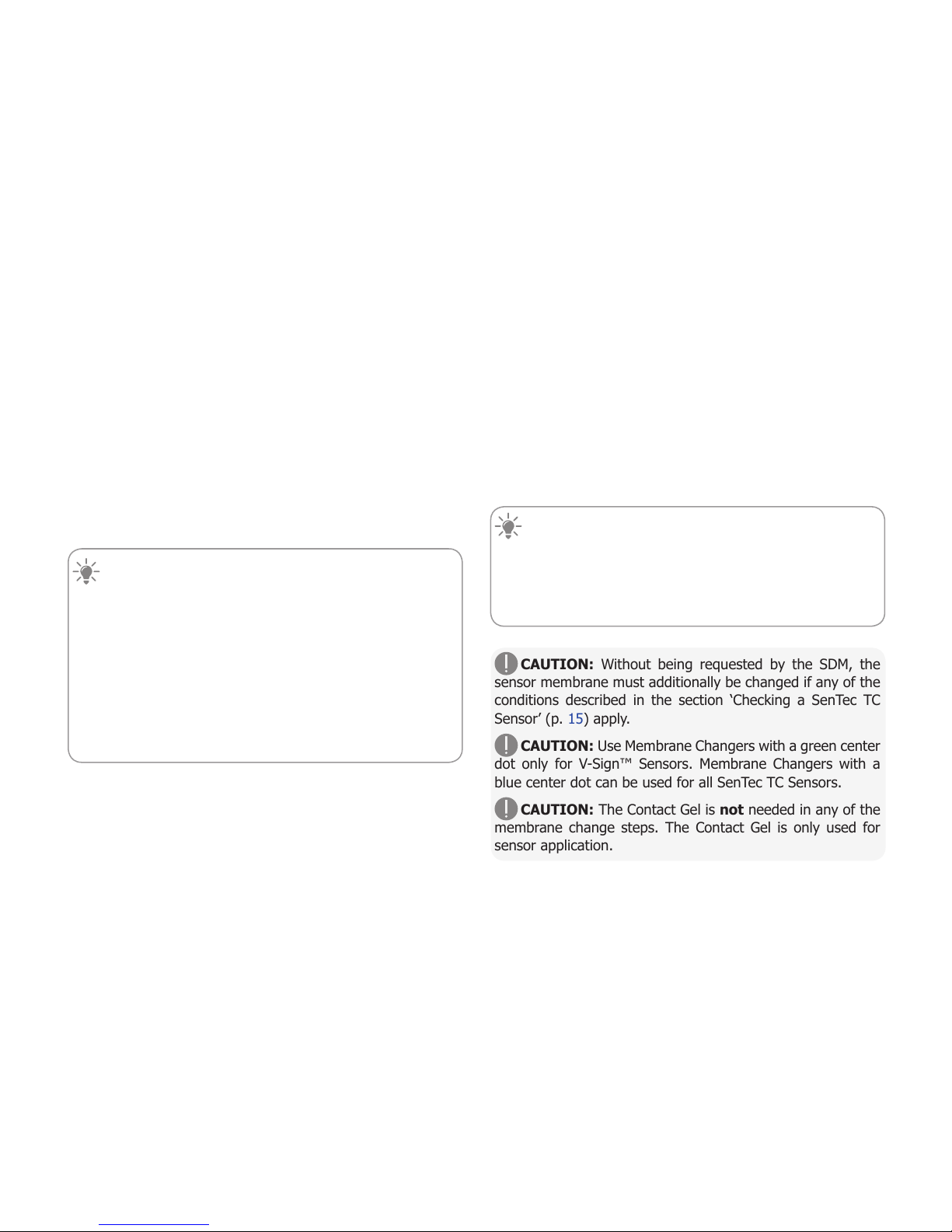
Note: A Membrane Change Tutorial is available for
online viewing at www.sentec.com/tv/v0.
Note: The Membrane Changer can be reused
by replacing its insert. To prepare the Membrane
Changer for reuse, refer to the Directions for Use
of the Membrane Changer Inserts or see tutorial at
www.sentec.com/tv/v1.
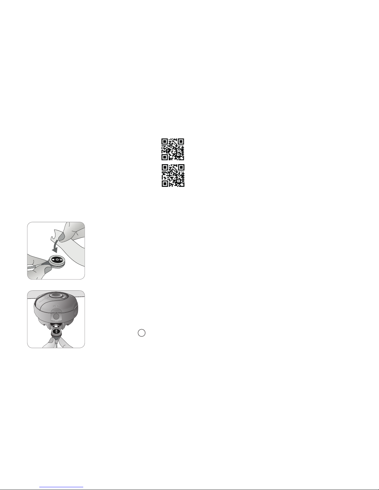
Inserting Sensor into Membrane Changer
1. Verify that the sensor is clean before
changing its membrane. If necessary,
carefully wipe off any residue from
the sensor’s surface (including
membrane, housing and cable) with
70% isopropanol (for other approved
cleaning agents refer to the sensor’s
Directions for Use).
2. Place the Membrane Changer on
a horizontal, dry surface with the
colored dot facing up.
3. Insert the sensor into the Membrane
Changer with the sensor side facing up.
The insert receiver 1is designed so
that improper alignment of the sensor
is difficult if not impossible.
Note: Neither touch nor hold the sensor cable while the sensor
is inside in the Membrane Changer nor pick up the Membrane
Changer as this may lead to dislodging the sensor from the
Membrane Changer.
Four Press-and-Turn Steps
to Change the Membrane
The membrane change procedure consists of four identical
press-and-turn steps. To provide better guidance, these steps
are marked with the corresponding numbers on the Membrane
Changer.
Step 1 removes the old sensor membrane: Press down slowly
but firmly with palm of hand and hold for 3 seconds. Release
the top Carry out a visual check to ensure that the membrane
is removed. Turn the top portion one click clockwise to the next
step. Keep the Membrane Changer horizontal.
Step 2 cleans the sensor surface from old electrolyte: As in
step 1, press the membrane changer slowly but firmly, release
the top and turn clockwise to the next step.
Step 3 applies new electrolyte on the sensor surface: Press
the membrane changer slowly but firmly for 3 seconds, release
the top and turn clockwise to the next step.
Step 4 places a new membrane on the sensor: Press the
membrane changer top down slowly but firmly for 3 seconds,
release the top and turn clockwise to the √ symbol.
This manual suits for next models
2
Table of contents
Other Sentec Medical Equipment manuals


Popular Medical Equipment manuals by other brands


Vitalograph
Vitalograph 2120 User instructions

NeurOptics
NeurOptics PLR-4000 quick start guide

MHC Medical Products
MHC Medical Products SureLife Clearwave user manual

Cardinal Health
Cardinal Health Kangaroo Quick reference guide

Mediana
Mediana RESCATE PERU Heart On AED A10 quick start guide

Intelect
Intelect Legend 2 user manual