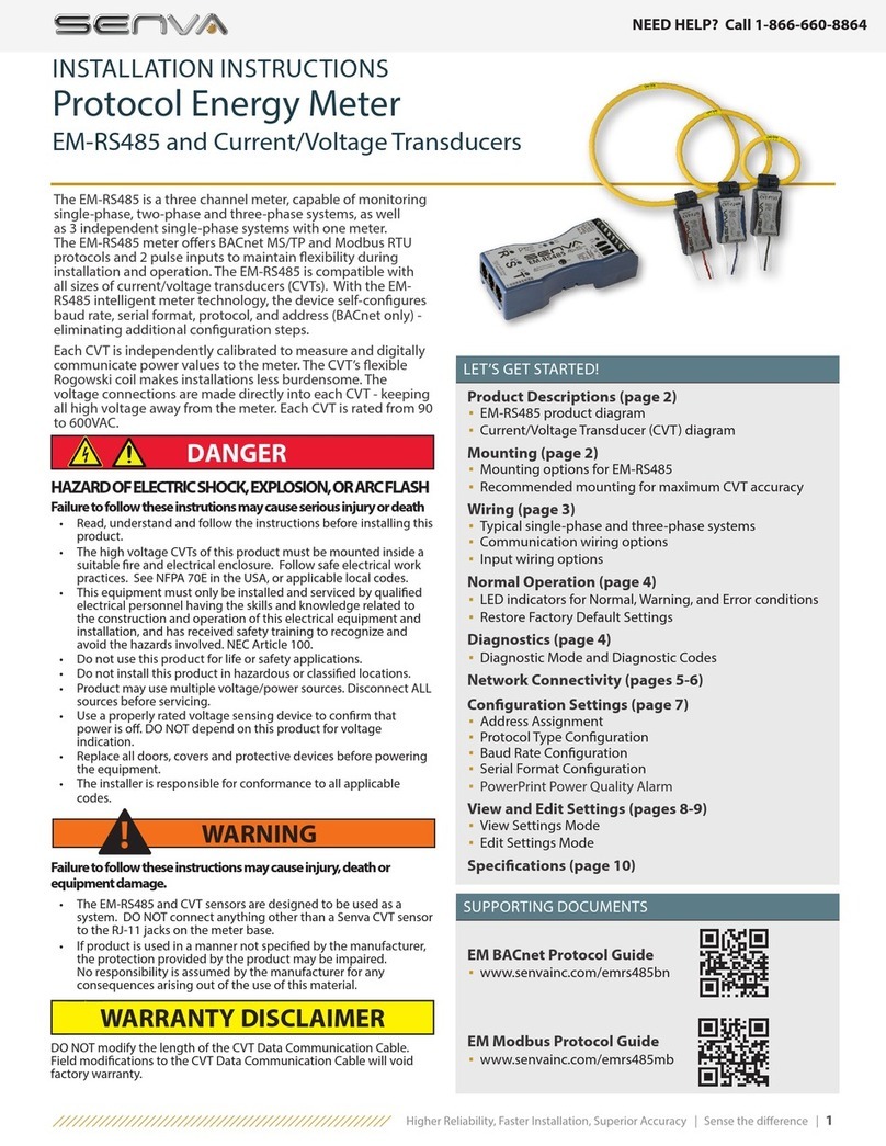
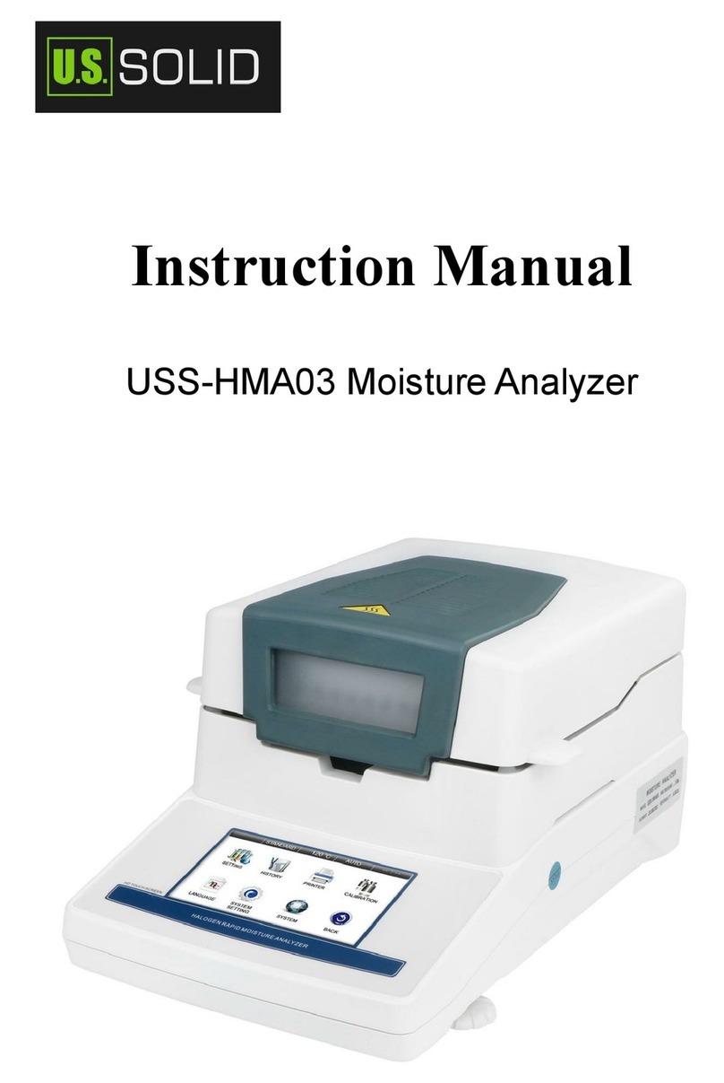
senva AQD Duct Series User manual

INSTALLATION INSTRUCTIONS
senvainc.com 1-866-660-8864 (F)1-503-296-2529 9290 SW Nimbus Ave. Beaverton Oregon 97008
AQD Duct Series
AQO Outdoor Series
Analog and BACnet versions
CO2/RH/T Combination Sensor
IMPORTANT WARNINGS
• Only qualied trade installers should install this product
• This product is not intended for life-safety applications
• Do not install in hazardous or classied locations
• The installer is responsible for all applicable codes
• De-energize power supply prior to installation or service
PRODUCT APPLICATION LIMITATION:
Senva products are not designed for life or safety applications.
Senva products are not intended for use in critical applications
such as nuclear facilities, human implantable device or life sup-
PRODUCT IDENTIFICATION
OPERATION
The AQ series design allows customization for a sensor that
meets project requirements for monitoring temperature, CO
and relative humidity. The product can be ordered for outdoor
or duct mount and with a 0-5/10V analog or BACnet RS485
output.
To verify the features see the ‘Product Identication’ section of
the installation manual.
RTD/Thermistor*
A = None
C = 100Pt (385) RTD
D = 1000Pt (385) RTD
E = 10k type 2
F = 10k type 3
Output
CO2 Sensor
A = None
B = CO Sensor
D = Dual Channel CO2
RH Sensor
A = None
B = 2% RH Sensor
Output Type
A = Analog (0-5/10V)
B = BACnet
CO RH RTD/TH
D
*Add-on RTD/Thermistor is not readable via BACnet.;
Temperature output is standard on AQ devices.
AQ -
Package
D = Duct
O = Outdoor
INSTALLATION
AQD (Duct) Installation
1. Drill a 3/4” hole in duct. Install sensor using gasket and
screws provided. The pickup tube will ensure adequate air ow
regardless of air ow direction.
2. Mount unit to duct with supplied screws. Continue to step 3
under general installation.
AQO (Outdoor) Installation
1. Select an outdoor location under an eave on north side of
building away from direct sunlight and rain exposure.
2. Mount product to building with supplied screws. Continue
to step 3 under general installation.
General (both) Installation
3. If installing with a conduit adapter, remove and replace the
factory-installed cable gland.
4. Wire analog (or RS485 for BACnet version) outputs as needed.
5. Apply power to sensor.
6. Tighten cable gland rmly around wires. If installing with a
conduit adapter, seal wire entry to prevent conduit air from
aecting sensor readings or operation.
7. Close lid and tighten screw. Cover must be securely installed
to prevent moisture from entering enclosure.
AQD (Duct) AQO (Outdoor)
G = 10k w/11k
H = 3k
I = 2k2
J = 1k8
K = 20k

WIRING
QUICK START MENU
1. Press and hold qand u(left and middle) buttons for 1
second to enter the Quick Start Menu that is adjustable using
the LCD. Screen will display SPt when the menu has been
activated.
2. Navigation and parameters:
• Pressing uadvances to the next menu item.
• If a menu item is visible, pressing either qor pdisplays the
current value.
• If a value is visible, pressing either qor pchanges the value.
Holding qor pfor a time accelerates the value change.
• If a value is visible, pressing qand ptogether sets the value
to the default.
• If a value is visible, pressing ureturns to the menu item list.
SPt Sets the relay turn-on threshold (Closed
above this level); Default: 800
SPhSets the relay turn-o hysteresis (Open below
this level); Default: 100
SCLSets the CO2 concentration scaling (2=
2000ppm (default); 5= 5000ppm, 10 = 10000ppm)
ADjSets the CO2 concentration calibration oset up to +/-
250ppm; Default: 0ppm
CALSets the CO2 auto calibration period
OFF Auto calibration disabled*, 7d 7 days,14d 14 days
(default), 30d 30 days, 60d 60 days
°FCSelects the unit system for displayed temperature
measurements UsRUser dened (default), °FDegrees
Fahrenheit, °CDegrees Celsius
LvLOutput Scaling (analog version only): 5v5.0V full
scale, 10v 10.0V full scale (default)
RUNClose this menu with changes saved and display
parameters.
3. When setup is complete, select RUN or wait for setup mode
to time out.
*If auto calibration is disabled, sensor may experience drift. Use
in areas that are continuously occupied or with concentrated
levels of CO such as greenhouses should consider dual-
channel sensor options. Consult factory for more information.
POWER VIN
GND/COMMON
N.O. RELAY
N.O. RELAY
T
C
H
ALL MODELS:
OUT CO
OUT RH
OUT TEMP
RS485 -
AGND
RS485 +
THERMISTOR
RESISTANCE
OUTPUT
1TERMINALS - ALL MODELS
2TERMINALS - ANALOG ONLY
3TERMINALS - BACNET ONLY
1PARTS LIST:
(-)
(+) -
+
0-5/10VDC CO2 ANALOG
OUTPUT TO CONTROLLER
1EXAMPLE ANALOG OUTPUT:
BACNET ONLY:
ANALOG ONLY:
OPTIONAL:
SPARE
C
T
H
(-)
(+)
5
4
9
678
1
10
2 3
4DISPLAY
5THERMISTOR OUTPUT (OPTION)
6DOWN BUTTON
7MENU BUTTON
8UP BUTTON
9REPLACEABLE CO SENSOR
10 TEMP/RH SENSOR
3
2
1
C
QUICK START MENU - BACNET
IMPORTANT: The device will not activate the BACnet interface
until the baud rate and the MS/TP MAC address are congured.
If an active RS485 network is not available, congure the device
using the Setup Menu (documented in the ‘AQ Series User’s
Guide’).
Access the auto conguration wizard by removing the front
cover and pressing the q, u, and p(all three) buttons for one
second. After the wizard activates, the display will show CFG.
The wizard automatically advances between each step after a
few seconds. Pressing the ubutton also advances the wizard.
bR The baud rate value can usually be detected from
existing network activity. If no baud rate could be
detected, the display will show ??. If necessary, use q
and pto change the baud rate before advancing.
AdR The device detects the smallest free MAC address on
the local MS/TP subnet from existing network activity.
If the installation requires a specic MAC address,
use qand pto override the detected address. If the
wizard detects that the selected MAC address
conicts with another device, it automatically
advances to the next smallest free MAC address.
After the wizard completes, the device saves the baud rate and
MS/TP MAC address. Additionally, the device adds 665000 to
the selected MAC address and saves the resulting sum as the
device object ID. If the object ID conicts with another device,
use id.1,id.2, and id.3 in the Setup Menu to set a unique
object ID.
The BACnet interface becomes active immediately after the
wizard completes. To recongure the baud rate and MAC
address, use the Setup Menu or run the wizard again.

VISUAL INDICATORS
Each measurement should display in turn.
If a measurement does not appear, the respective sensor
damaged, has been removed from the device, or has been
selected not to appear through the User’s Menu (See ‘AQ Series
User’s Guide’).
BACnet Only:
The baud rate and MAC address must be congured before the
device begins transmitting.
The RX light (receiving indicator) will ash while data is being
received. If the RX light is not blinking, verify the wiring
conguration and wiring connections.
The TX light (transmitting indicator) will ash while data is
being transmitted.
HOME SCREEN
By default, the device displays one measurement at a time,
rotating between measurements every 10 seconds if multiple
sensor options are installed.
If the installer wants to change which values are displayed on
the LCD, access the User’s Menu (See ‘AQ Series User’s Guide’).
TROUBLESHOOTING
Symptom Solution
No output Check wiring. Ensure power supply
meets requirements.
Reading error
Verify unit is located away from
hot/cold sources.
Verify control panel software is
congured correctly.
Verify accuracy of test instrument.
Install insulation behind sensor to
prevent air ow from inside wall.
MENU OPTIONS
To access the full menu options use the ‘AQ Series User’s Guide’
manual online at www.senvainc.com/download_center.asp
The ‘AQ Series User’s Guide’includes:
-User’s Menu
-Setup Menu
-Quick Start Menu
-Diagnostics
SENVA TECHNICAL SUPPORT
Need futher assistance? Call our toll-free number for live
technical support: (866) 660-8864 or feel free to email us at
DIMENSIONS
AQD Dimensions
AQO Dimensions
OBJECT LIST MANUAL
For further reading access the object list and conformance
statement‘AQ Series BACnet Protocol Guide’ found online at
www.senvainc.com/download_center.asp
The ‘AQ Series BACnet Protocol Guide’ includes:
-Protocol Implementation Conformance Statement
-Supported Objects
-Supported Properties

SPECIFICATIONS
Power Supply 12-30VDC/24VAC(1), 100mA max.
Analog Outputs
(Analog Version Only)
Temperature 0-5/10V standard; Scaling 50°F to 95°F (10°C to 35°C); Thermistor/RTD values optional
CO2 and RH 0-5/10V
Update Rate Continuous
Programmable Relay Solid-state output, 1A @ 30VAC/DC, N.O.
Protocol Output (BACnet
Version Only)
Protocol BACnet
Conection 3-wire RS-485, with isolated ground
Data Rate Locally set baud rate up to 115200 (9600, 19200, 28800, 38400, 57600, 76800, 115200)
Address Range 0-127
Bus Load 1/8th unit (256 nodes maximum on bus)
Programmable Relay Solid-state output, 1A @30VAC/DC, N.O. Source Selectable: CO, RH, Temperature
CO
Type Non-dispersive Infrared (NDIR)
Accuracy (Standard)
±(30ppm +3% of reading) (400-2000ppm), @-10-50°C
±(50ppm +5% of reading) (2000-5000ppm), @-10-50°C
±(100ppm+10% of reading) (5000-10000ppm), @ 0-50C
Accuracy (Dual-Channel option)
±(30ppm+3% of reading) (0-2000ppm), @ 0-50C
±(50ppm+3% of reading) (2000-5000ppm), @ -10-50C
±(100ppm+10% of reading) (5000-10000ppm), @ 0-50C
Drift with ABC disabled (Standard) < 35ppm/month
Drift with ABC disabled (Dual Channel) < 5ppm/month
Pressure Dependence +1% reading per 1kPa (0.146PSI) deviation from nominal pressure (101kPa, 14.7PSI)
Range 0-2000/5000/10000ppm (2000ppm default); Programmable up to 10,000ppm
Response time 30s
Sample rate 1s
Relative Humidity
Type Digital CMOS
Accuracy 2% models, +/-2% over 10 to 90%RH range
Resolution 0.05%RH
Hysteresis +/-1%RH
Temperature coecient Compensated on-board
Response time (2) 30s
Sample rate 3s
Operating range/Output Scale 0 to 100%RH (non-condensing)
Long term drift <0.5%RH per year
Operating conditions (4) -20° C to 60° C @ RH>90%
-20° C to 80° C @ RH=50%
Type Silicon Bandgap
Temperature
(with RH element)
Nominal Accuracy +/-0.3° C (operating range)
Maximal Accuracy +/-0.5° C (at 25° C), +/-1.0° C (operating range)
Resolution 0.01° C
Repeatability +/-0.1° C
Response time 30s
Sample rate 3s
Type NTC Thermistor
Nominal Accuracy +/-0.5° C (operating range)
Temperature Maximal Accuracy +/-1.0° C (at 25° C), +/-2.0° C (operating range)
(without RH element) Resolution 0.05° C
Repeatability +/-0.2° C
Sample Rate 100 milliseconds
Operating Environment Temperature -4 to 122F (-20 to 50° C)
Humidity 0-95% non-condensing
Enclosure Material ABS/Polycarbonate
Dimensions 4.0”h x 4.4”w x 2.1”d (AQD: +6.8”probe) (AQO: +2.8”solar shield)
Revised 04/29/2020 Document #152-0376-0B
This manual suits for next models
1
Other senva Measuring Instrument manuals

