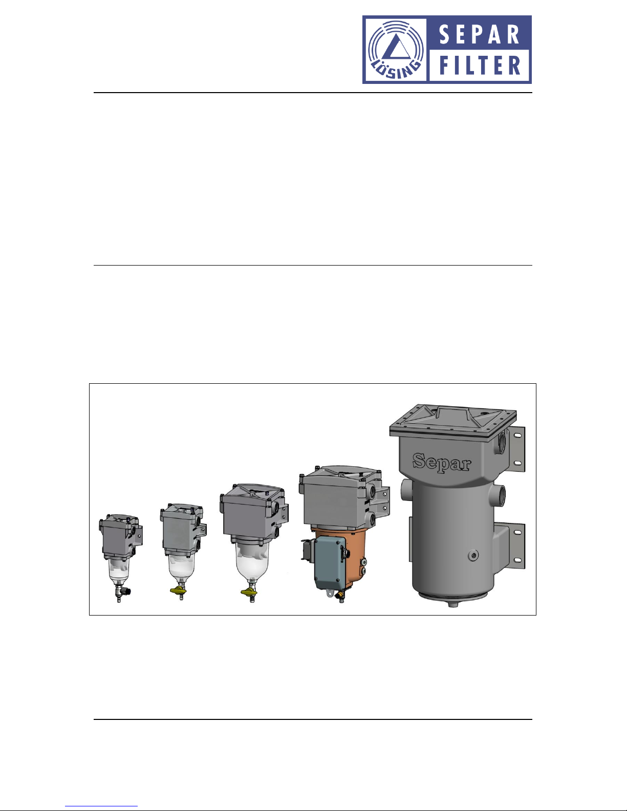
Separ Filter SWK-2000 User manual
Dok.-Nr.: D10029.EN Rev.: 11 Page 1of 30
Manual: Water separator / Fuel pre-filter SWK-2000
Willibrord Lösing
Filterproduktion GmbH
W. Lösing Filterproduktion GmbH • Am Walzwerk 2 • 45527 Hattingen
Operating Manual
Water separator / Fuel pre-filter SWK-2000
Dok.-Nr.: D10029.EN Rev.: 11 Page 2of 30
Manual: Water separator / Fuel pre-filter SWK-2000
Willibrord Lösing
Filterproduktion GmbH
W. Lösing Filterproduktion GmbH • Am Walzwerk 2 • 45527 Hattingen
Table of contents
General information...................................................................................................... 41
1.1 Disclaimer............................................................................................................................................4
1.2 Symbols used ...................................................................................................................................... 4
1.3 Safety instructions............................................................................................................................... 4
1.4 Intended use .......................................................................................................................................5
Introduction.................................................................................................................. 62
2.1 Why Separ...........................................................................................................................................6
2.2 Function of the SWK-2000 .................................................................................................................. 6
2.3 Fields of application of the filter.........................................................................................................7
2.4 Tests and Certificates.......................................................................................................................... 8
Delivery ........................................................................................................................ 93
3.1 Scope of delivery.................................................................................................................................9
3.2 Unpacking............................................................................................................................................9
3.3 Storage ................................................................................................................................................ 9
Technical description .................................................................................................. 104
4.1 General arrangement drawing..........................................................................................................10
4.2 Dimensions and weights ...................................................................................................................12
4.3 Characteristics................................................................................................................................... 12
4.4 Available options...............................................................................................................................13
4.5 Materials used...................................................................................................................................14
4.6 Electrical data.................................................................................................................................... 14
4.7 Mechanical connections ...................................................................................................................14
4.8 Temperature ranges..........................................................................................................................14
Filter combinations ..................................................................................................... 145
5.1 Switch-over system ...........................................................................................................................15
5.2 Double-unit system...........................................................................................................................17
Options....................................................................................................................... 186
6.1 Filter heating .....................................................................................................................................18
6.1.1 Heating system SWK-2000/5/50, /10 and /18..................................................................................18
6.1.2 Fuel pre heating system SWK-2000/40/MH or MHS ........................................................................19
6.2 Water in fuel sensor (WIF) ................................................................................................................21
6.3 Differential pressure switch..............................................................................................................21
6.4 Relative pressure switch ................................................................................................................... 21
6.5 Vacuum gauge...................................................................................................................................22
6.6 Bowl...................................................................................................................................................22

Dok.-Nr.: D10029.EN Rev.: 11 Page 3of 30
Manual: Water separator / Fuel pre-filter SWK-2000
Willibrord Lösing
Filterproduktion GmbH
W. Lösing Filterproduktion GmbH • Am Walzwerk 2 • 45527 Hattingen
Assembly .................................................................................................................... 237
7.1 Selection of mounting position.........................................................................................................23
7.2 Filter installation ...............................................................................................................................23
7.3 Electrical connection......................................................................................................................... 24
7.4 Disassembly....................................................................................................................................... 24
Commissioning............................................................................................................ 258
Maintenance............................................................................................................... 269
9.1 Tightening torques............................................................................................................................26
9.2 Drainage of water ............................................................................................................................. 26
9.3 Back-flushing process........................................................................................................................27
9.4 Element replacement........................................................................................................................27
9.5 Cleaning.............................................................................................................................................28
Repair......................................................................................................................... 2810
Accessories ................................................................................................................. 2911
Disposal ...................................................................................................................... 3012
Annex B: Specific drawings.......................................................................................... 3013
Dok.-Nr.: D10029.EN Rev.: 11 Page 4of 30
Manual: Water separator / Fuel pre-filter SWK-2000
Willibrord Lösing
Filterproduktion GmbH
W. Lösing Filterproduktion GmbH • Am Walzwerk 2 • 45527 Hattingen
General information1
1.1 Disclaimer
The preparation of this document was made as carefully as possible. However, errors can not be
excluded. Therefore, we do not take over any liability for errors or deficits in this document, nor for
any consequential damages which may arise there from.
We reserve the right to make technical changes to this document or the product described herein
without notice.
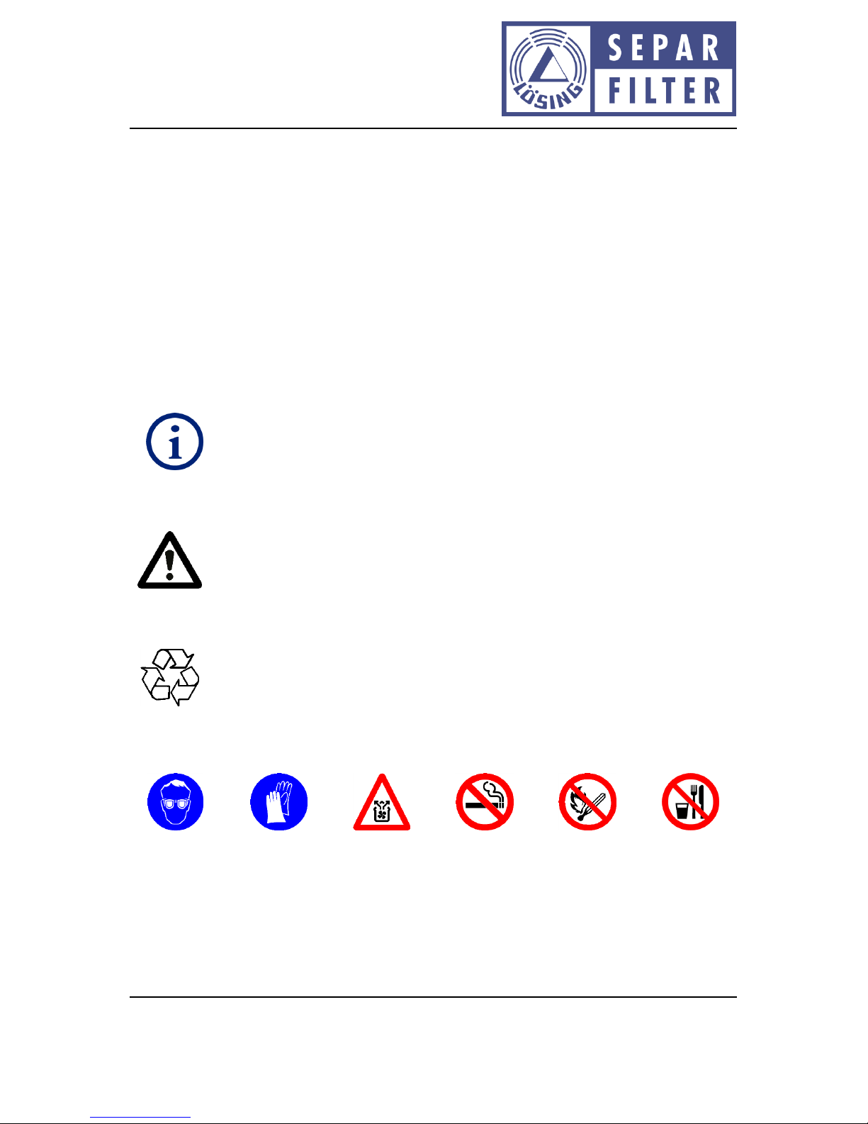
1.2 Symbols used
The following symbols are used in this document to visually emphasize important information and
warnings:
Note
Note on special tips and other helpful or important information.
Attention
Disregarding these instructions may damage the fuel filter or the mashine where the
filter is mounted.
Disposal
Note on special measures for protection of the environment / surroundings and
disposal of the system or parts of the system.
1.3 Safety instructions
Wear goggles
Wear
protective
gloves
Ventilate the
work area
Refrain from
smoking
No open fire
No food in the
work area
Works on the system have to be performed by trained personal only and in compliance with the
applicable work safety regulations. Generally operate on a cut-off, voltage-free system.

Dok.-Nr.: D10029.EN Rev.: 11 Page 5of 30
Manual: Water separator / Fuel pre-filter SWK-2000
Willibrord Lösing
Filterproduktion GmbH
W. Lösing Filterproduktion GmbH • Am Walzwerk 2 • 45527 Hattingen
The filter may be under pressure. Therefore never open a filter in operation, otherwise fuel may leak
into the environment and the engine draws air, which can cause damage to the engine.
When using duplex or switchable filters, the lever position indicates which filter is in operation. At
this moment the other filter is isolated from the fuel circuit, but still could contain fuel.
Filters with fuel pre heating systems may only be placed in operation when completely filled with
fuel and primed of air.
The electrical current for the heater must never be turned on without grounding and activated
associated control system.
Remove spilled fuel immediately and dispose them in accordance with the applicable statutory
provisions (s. cha. 12).
1.4 Intended use
The filter is intended for the filtration of diesel fuels and mineral oils with a dynamic viscosity < 10
mPas, flash point > 55 °C and boiling point > 160 °C and is designed for operation in between fuel
tank and fuel lift pump (suction side). The filter should never be installed on the pressure side,
behind the fuel pump.

Dok.-Nr.: D10029.EN Rev.: 11 Page 6of 30
Manual: Water separator / Fuel pre-filter SWK-2000
Willibrord Lösing
Filterproduktion GmbH
W. Lösing Filterproduktion GmbH • Am Walzwerk 2 • 45527 Hattingen
Introduction2
2.1 Why Separ
In 1992, the generation SWK-2000 water separators / fuel filter was developed by the company W.
Lösing Filtertechnik e. K. as an effective system for the separation of water and dirt particles which
are contained in the fuel. Both water and dirt can lead to high wear and tear on engines as well as
the injection systems and result in expensive, intensive repairs and equipment down time.
SWK-2000 offers:
Smallest and most compact design
High separation efficiency
Low flow resistance
Long life filter element
Easy installation
Simple maintenance
Different flow rates
Minimal maintenance effort
Enviroment friendly
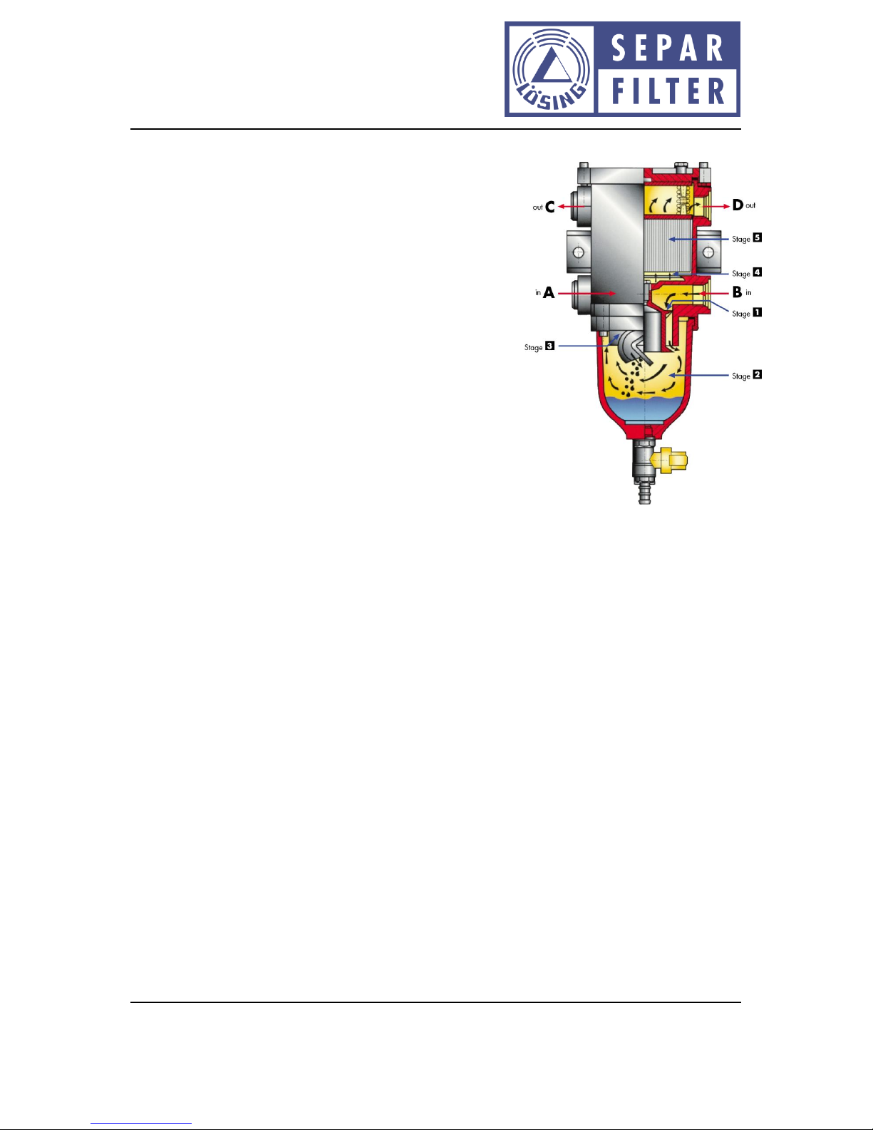
2.2 Function of the SWK-2000
The separation and purification process using a special patented system that is used throughout all
of the different sizes, which stick out through most compact design in relation to the effective flow
rate.
Generally, the SWK-2000 is installed on the vacuum side of the fuel system, i. e. between fuel tank
and fuel pump.
The fuel enters the filter through one of the two inlet parts, the unused port must be sealed off with
the attached plug.
Stage 1
From the inlet port, fuel flows into the filter and passes an interior vane system whereby the fuel is
moved in an intensive circular motion.
Stage 2
The centrifugal gravity, resulting from the circular motion, forces the fuel to the outer wall of the
bowl. The heavier water droplets and heavier particles collect on the wall of the bowl and settle due
to natural gravity to the bottom of the bowl.
Dok.-Nr.: D10029.EN Rev.: 11 Page 7of 30
Manual: Water separator / Fuel pre-filter SWK-2000
Willibrord Lösing
Filterproduktion GmbH
W. Lösing Filterproduktion GmbH • Am Walzwerk 2 • 45527 Hattingen
Stage 3
In the further flow the fuel passes the outer vane system. By
the different length of the vanes and the twofold change in the
fuel flow direction, smaller water droplets and fine dirt
particles settle on the vanes, where they agglomerate and than
decline, caused by gravity, down to the bottom of the bowl.
Already at this point the major portion of any contaminates in
the fuel have been separated.
Stage 4
Below the filter element, on the so-called dome, the flow
cross-section is considerably increased, whereby a slow-down
of the fuel occurs. This also allows smallest water droplets and
dirt particles to settle. Through the previous pre-separation,
the majority of the contamination (water and dirt) settles in
the bowl and prolongs significantly the lifetime of the filter
element.
Stage 5
The remaining suspended contamination in the fuel, finest water droplets and smallest particulates
are filtered by a replaceable filter element which is produced from a special cellulose paper or
stainless steel mesh elements.
The clean fuel leaves the filter through one of the outlet ports (the port not required should be
sealed off with the plug attached) and continues through thefuel system.
2.3 Fields of application of the filter
Vehicle industry –trucks, busses, crane trucks, municipal vehicles, etc.
Construction machinery, agricultural machinery, forklifts, compressors, etc.
Ship propulsion motors, auxialliary units
Stationary engines and generators, welding and pumping units
Mining machinery, rail vehicles

Dok.-Nr.: D10029.EN Rev.: 11 Page 8of 30
Manual: Water separator / Fuel pre-filter SWK-2000
Willibrord Lösing
Filterproduktion GmbH
W. Lösing Filterproduktion GmbH • Am Walzwerk 2 • 45527 Hattingen
There are also versions available for special applications.
Specifically for marine or prime power application duplex or switchable filters are offered. Thereby a
filter can always be serviced, while the other filter is under flow without engine shut down.
For engines burning biodiesel appropriate versions are available.
For winter operation the SWK-2000 filter is available with pre-heating systems.
For hot environments there are custom high-temperature variants available.
2.4 Tests and Certificates
The SWK-2000 has various approvals and certificates. Copies can be provided on request. Below is a
list of organizations that have carried out these tests.
Rheinisch-Westfälischer TÜV
KBA - Kraftfahrt-Bundesamt Flensburg
German Technical Department for Army Ship and Marine Weapons
GL - Germanischer Lloyd Type Approval Certificate
Bureau Veritas Type Approval Certificate
RINA
ABS –American Board of Shipping
LR –Lloyds Registry London
Gost Standard
Fire Resistance Test by MPA –Material Prüfungsamt NRW
Dok.-Nr.: D10029.EN Rev.: 11 Page 9of 30
Manual: Water separator / Fuel pre-filter SWK-2000
Willibrord Lösing
Filterproduktion GmbH
W. Lösing Filterproduktion GmbH • Am Walzwerk 2 • 45527 Hattingen
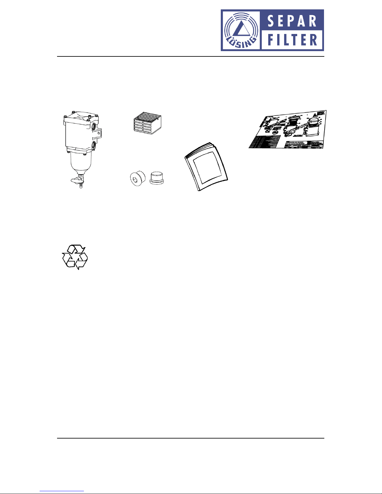
Delivery3
3.1 Scope of delivery
Check if you have the following accessories:
3.2 Unpacking
Before opening check the delivery for outer damage.Report any damage to carrier.
DISPOSAL
Please follow the environmental guidelines and laws of your country. Make sure the
the packaging material is disposed according to applicable regulations.
3.3 Storage
The filter and its accessories must be kept dry and in compliance with the maximum permitted
temperature ranges (s. chap. 5.8).
During a long storage period you should close all openings on the filter in order to protect the
interior and the filter element from unnecessary pollution. All filters out of the factory have all ports
sealed with plastic plugs.
Filter assembly
(s. chap. 4.1)
Operating instruction
Filter element
(already installed)
specific drawings
(upon request)
2 plugss

Dok.-Nr.: D10029.EN Rev.: 11 Page 10 of 30
Manual: Water separator / Fuel pre-filter SWK-2000
Willibrord Lösing
Filterproduktion GmbH
W. Lösing Filterproduktion GmbH • Am Walzwerk 2 • 45527 Hattingen
Technical description4
4.1 General arrangement drawing
Using the example of the SWK-2000/10:
FilterLid
Filter housing
Bleed screw
Mounting bracket
Mounting hole
Fuel inlet
(similar to the right filter side)
Fuel outlet
(similar to the right filter side)
bowl
Thread for water in fuel sensor
(on the right side)
Drain valve
Socket for heater control

Dok.-Nr.: D10029.EN Rev.: 11 Page 11 of 30
Manual: Water separator / Fuel pre-filter SWK-2000
Willibrord Lösing
Filterproduktion GmbH
W. Lösing Filterproduktion GmbH • Am Walzwerk 2 • 45527 Hattingen
Using the example of the SWK-2000/40/M/H:
Example of a filter element:
The filter shown here may differ from your purchased filter. The actual appearance and arrangement
of the components depends on the configuration of the filter you have chosen.
Filter lid
Filter housing
Bleed screw
Mounting
surface
Mounting hole
Fuel inlet
(similar to the left filter side)
Fuel outlet
(similar to the left filter side)
Bowl
2 sealed ports for water in fuel sensors
Drain valve
Heating electronics
(optional)
Connector for
heater
Socket for heatercontrol. Note to be
connected before heater plug
Grounding point
top
bottom
Handle
as replacement aid

Dok.-Nr.: D10029.EN Rev.: 11 Page 12 of 30
Manual: Water separator / Fuel pre-filter SWK-2000
Willibrord Lösing
Filterproduktion GmbH
W. Lösing Filterproduktion GmbH • Am Walzwerk 2 • 45527 Hattingen
4.2 Dimensions and weights
SWK-
2000/5
SWK-
2000/5/50
SWK-
2000/10
SWK-
2000/18
SWK-
2000/40
SWK-
2000/130
Width
140 mm
/WSA:
210 mm
140 mm
150 mm
/WSA:
220 mm
210 mm
290 mm
420 mm
Hight
275 mm
310 mm
340 mm
410 mm
470 mm
720 mm
Depth
90 mm
90 mm
110 mm
165 mm
250 mm
370 mm
Weight
< 2,5 kg
< 2,7 kg
< 3 kg
< 8 kg
< 15 kg
< 55 kg
Mountig holes
2 x Ø 9 mm
2 x Ø 9 mm
2 x Ø 9 mm
4 x Ø 9 mm
4 x Ø 12 mm
8 x Ø 15 mm
The dimensions of filter combinations may differ (see Chapter 5)
4.3 Characteristics
SWK-
2000/5
SWK-
2000/5/50
SWK-
2000/10
SWK-
2000/18
SWK-
2000/40
SWK-
2000/130
Flow performance
5 l/min
5 l/min
10 l/min
18 l/min
40 l/min
130 l/min
Complete interior
volume
450 ± 30 ml
700 ± 35 ml
1200 ± 50ml
3100 ± 90ml
7000 ± 200
ml
40 ± 1 l
Water-holding
capacity
120 ± 10 ml
120 ± 10 ml
240 ± 20 ml
500 ± 30 ml
1500 ± 50
ml
8,5 ± 0,5 l
Alarm on water
quantity
80 ± 10 ml
80 ± 10 ml
140 ± 20 ml
300 ± 30 ml
1250 ± 50
ml
7 ± 0,5 l
Water-holding capicity
with heater
-
100 ± 10 ml
200 ± 20 ml
450 ± 30 ml
1100 ± 50
ml
-
Alarm on water
quantity (with heater)
-
70 ± 10 ml
140 ± 20 ml
300 ± 30 ml
1) 350 ± 50
ml
2) 950 ± 50
ml
-
Max. allowable
pressure
15 bar
15 bar
12 bar
7 bar
4 bar
2 bar
Water separation
> 99 % des freien Wassers1
Available filter units
10 µm (coated cellulose paper)
30 µm (coated cellulose paper)
30 µm (stainless steel mesh)
60 µm (stainless steel mesh)
The characteristics of filter combinations may differ (see Chapter 5)
1
The water separation was detected at W. Lösing Filterproduction GmbH based on the DIN 4020 and the
ISO-TS 16332.

Dok.-Nr.: D10029.EN Rev.: 11 Page 13 of 30
Manual: Water separator / Fuel pre-filter SWK-2000
Willibrord Lösing
Filterproduktion GmbH
W. Lösing Filterproduktion GmbH • Am Walzwerk 2 • 45527 Hattingen
Pressure drop
2
4.4 Available options
SWK-2000/5
SWK-2000/10
SWK-2000/18
SWK-2000/40
SWK-2000/130
heating
x3
x
x
x
-
Water sensor
x
x
x
x
x
Relative
pressure switch
x
x
x
x
X
Differential
pressure switch
x
x
x
x
x
Clogging
indicator
x
x
x
x
x
Transp. bowl
x
x
x
-
-
Metal bowl
x
x
x
x
X
Heavy-Duty
design
x
Not applicable because only Heavy-Dutiy version available.
2
All pressure losses were measured with diesel according to EN590 at 20 °C ± 2 °C fuel and ambient
temperature.
3
Only in connection with option /50
Pressure drop of SWK-2000/5
Pressure drop [mbar]
Flow rate [l/min]
Pressure drop [mbar]
Flow rate [l/min]
Pressure drop of SWK-2000/10
Pressure drop [mbar]
Flow rate [l/min]
Pressure drop of SWK-2000/18
Pressure drop [mbar]
Flow rate [l/min]
Pressure drop of SWK-2000/40

Dok.-Nr.: D10029.EN Rev.: 11 Page 14 of 30
Manual: Water separator / Fuel pre-filter SWK-2000
Willibrord Lösing
Filterproduktion GmbH
W. Lösing Filterproduktion GmbH • Am Walzwerk 2 • 45527 Hattingen
4.5 Materials used
Filter cover, filter housing
Aluminium
Bowl
Aluminium or transparent PA
Drain valve
Brass, PBT
Gaskets
TPE and/or HNBR
Bleed screw
Steel
Outboard screws
Stainless steel A2
4.6 Electrical data
Electrical components are installed only in conjunction with a filter heater, water in fuel sensor
and/or pressure switch. The electrical data on these options please refer to chaptures 6.1 and 6.2.
Filter sizes for which the above options are available please refer to chapture 4.4.
4.7 Mechanical connections
SWK-2000/5
SWK-2000/10
SWK-2000/18
SWK-2000/40
SWK-2000/130
Fuel inlet
M16x1,5
M22x1,5
M26x1,5
M33x2
G2“
Fuel outlet
M16x1,5
M22x1,5
M26x1,5
M33x2
G2“
Recommended
minimum-diameter
performance
8 mm
12 mm
20 mm
26 mm
40 mm
The dimensions of filter combinations may differ (see Chapter 5)
Adapter for the fuel inlet and fuel outlet can be obtained as an accessory through the W. Lösing
Filtertechnik e. K..
4.8 Temperature ranges
Filters are designed to operate in temperature range of -40 °C to 80 °C.
On the filter with fuel pre heating system, selected thermal fuses are installed. Fuses will be
irrevocably destroyed when ignoring the stated temperature limit.
Filter combinations5
In some areas of application it may be necessary to combine two structurally identical filters with
one another. Currently, two different combination options are offered.

Dok.-Nr.: D10029.EN Rev.: 11 Page 15 of 30
Manual: Water separator / Fuel pre-filter SWK-2000
Willibrord Lösing
Filterproduktion GmbH
W. Lösing Filterproduktion GmbH • Am Walzwerk 2 • 45527 Hattingen
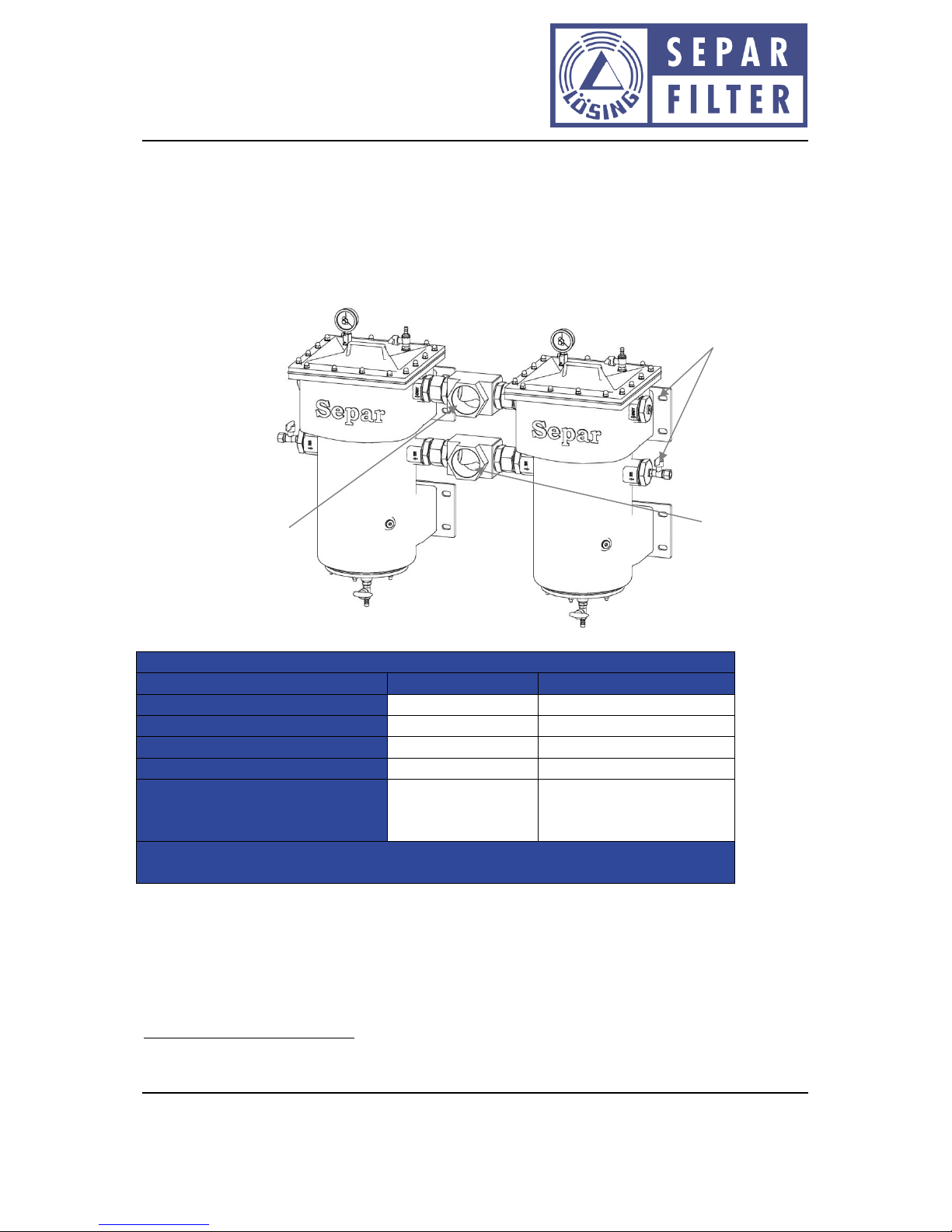
5.1 Switch-over system
A switch-over system (marked in the product key through the addition /U) is a redundant Separ filter
structure. The redundant system ensures uninterrupted operation of the filter system (e.g. during
maintenance work on the filter).
Example of a switch-over system4:
Both filters have a common fuel inlet and a common fuel outlet. Using the switch-over lever, the
filter through which the fuel should pass can be changed. The other respective filter is now no longer
part of the fuel circulation and can be emptied and opened for maintenance purposes (see Chapter
9). Operation of the switch-over system in other lever positions to those shown in the following
diagram is not permitted (move the lever only to the right or to the left as far as it will go)!
Left filter is active
Right filter is active
4Example includes special options
The standard
inlets and
outlets remain
closed
Fuel inlet
Fuel outlet
Switch-over lever
Dok.-Nr.: D10029.EN Rev.: 11 Page 16 of 30
Manual: Water separator / Fuel pre-filter SWK-2000
Willibrord Lösing
Filterproduktion GmbH
W. Lösing Filterproduktion GmbH • Am Walzwerk 2 • 45527 Hattingen
Deviations to Chapter 4.2 Dimensions and weights
SWK-
2000/5/U
SWK-
2000/5/50/U
SWK-
2000/10/U
SWK-
2000/18/U
SWK-
2000/40/U
SWK-
2000/130/U
Width [mm]
440
440
460
630
800
1,100
Height [mm]
300
340
380
450
530
860
Depth [mm]
160
160
200
230
280
430
Weight [kg]
< 8
< 8
< 10
< 20
< 40
< 120
Fixing holes
[mm]
2x slotted
holes (18x9)
Distance
apart: 416
2x slotted
holes (18x9)
Distance
apart: 416
4x slotted
holes (18x9)
Distance
apart: 435x85
4x slotted
holes
(24x12)
Distance
apart:
590x80
4x slotted
holes
(24x12)
Distance
apart: 760x100
16x slotted
holes (27x15)
Distance
apart:
See drawings
All sizes and weights may vary according to the precise configuration of the filter assembly. The exact
dimensions should be taken from the specific drawing of your filter.
The performance characteristics from Chapter 4.3 retain their validity for each individual filter.
Deviations to Chapter 4.7 Mechanical connections
SWK-
2000/5/U
SWK-
2000/10/U
SWK-
2000/18/U
SWK-
2000/40/U
SWK-
2000/130/U
Fuel inlet and
outlet
Union nut with a cutting ring for a pipe with an external diameter of
G2“
12 mm
15 mm
22 mm
35 mm
Dok.-Nr.: D10029.EN Rev.: 11 Page 17 of 30
Manual: Water separator / Fuel pre-filter SWK-2000
Willibrord Lösing
Filterproduktion GmbH
W. Lösing Filterproduktion GmbH • Am Walzwerk 2 • 45527 Hattingen
5.2 Double-unit system
In the case of a double-unit system, two identical filters are installed parallel in the fuel circulation.
By parallelising the filter, the double-unit system is able to achieve twice the flow rate as that of a
single filter.
Example of a double-unit filter system
4
:
Deviations to Chapter 4.2 Dimensions and weights
SWK-2000/40/2
SWK-2000/130/2
Width [mm]
870
1.100
Height [mm]
480
860
Depth [mm]
240
370
Weight [kg]
< 35
< 120
Fixing holes [mm]
4x slotted
holes (24x12)
Distance apart: 835x100
16x slotted holes (27x15)
Distance apart:
See drawings
All sizes and weights may vary according to the precise configuration of the filter assembly. The
exact dimensions should be taken from the specific drawing of your filter.
4
Example includes special options
The standard
inlets and
outlets remain
closed
Fuel inlet
Fuel outlet
Dok.-Nr.: D10029.EN Rev.: 11 Page 18 of 30
Manual: Water separator / Fuel pre-filter SWK-2000
Willibrord Lösing
Filterproduktion GmbH
W. Lösing Filterproduktion GmbH • Am Walzwerk 2 • 45527 Hattingen
Deviations to Chapter 4.3 Characteristics
SWK-2000/40/2
SWK-2000/130/2
Flow rate
80 l/min
260 l/min
Total interior volume
14 ± 0.2 l
80 ± 1 l
Water absorption capacity
3 ± 0.05 l
17 ± 0.5 l
Water volume alarm
2.5 ± 0.05 l
14 ± 0.5 l
Deviations to Chapter 4.7 Mechanical connections
SWK-2000/40/2
SWK-2000/130/2
Fuel inlet and
outlet
Union nut with a cutting ring for a pipe with an
external diameter of 42 mm
G3“
Options6
Please refer to chapture 5.4 which options are available for your filter.
6.1 Filter heating
Different heating coils are used as a heating element in the different filter sizes. The heating of the
filter size SWK-2000/40 is treated separately in one of the following chaptures. Heating controls of
SWK 2000/40/MH are operating differently than models SWK 2000/5/50/H, SWK 2000/10/H and
SWK-2000/18/H.
6.1.1 Heating system SWK-2000/5/50, /10 and /18
Types of fuel pre heating sytems
Operating voltage Heating power rating
12 VDC 250 W
24 VDC 300 W
24 VDC 450 W
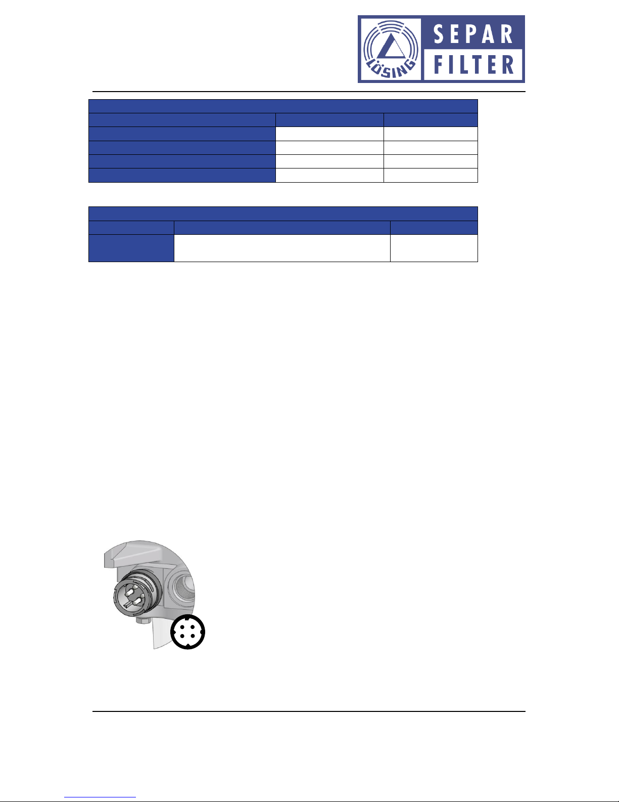
Heating connection
Connectors
Pin 1
GND
Pin 2
Control terminal
Pin 3
GND (not used for all types)
Pin 4
VCC (has to be protected by electric fuse)
When fuel temperature is <5 °C, the control signal is connected to ground. At temperatures >10 °C,
the signal is interrupted.
4
2
1
3

Dok.-Nr.: D10029.EN Rev.: 11 Page 19 of 30
Manual: Water separator / Fuel pre-filter SWK-2000
Willibrord Lösing
Filterproduktion GmbH
W. Lösing Filterproduktion GmbH • Am Walzwerk 2 • 45527 Hattingen
External interconnection
6.1.2 Fuel pre heating system SWK-2000/40/MH or MHS
In the heated filter of the SWK-2000/40 series, a heating power of 1400 W is fed into the fuel. The
heating system is in a 230 V and a 440 VAC version available.
Attention
The heater voltage must always be switched to the filter via an external contactor
with sufficient breaking capacity. The heater voltage may only be switched on when
the contact between pins C and D (Hummel connector: 3 and 4) of the control
terminal is closed. In case of interruption between pins C and D (Hummel connector: 3
and 4) the heater voltage must be switched off immediately! Other switching states
can cause damage to the heating filter.
Control electronics
The control electronics are identical for all versions of the filters described here.
Operating voltage: 24 VDC
Maximum operating voltage: 36 VDC
Minimum operating voltage: 16 VDC
Power input: < 10 W
Types of heatin systems
Operating voltage: heater power rating
230 VAC (50 Hz/60 Hz): 1400 W
440 VAC (50 Hz/60 Hz): 1400 W
Voltage by ignition key
Battery voltage
relay (e. g.: Bosch 0 332 019 150) for 12 V
relay (e. g.: Bosch 0 332 019 203) for 24 V
Rotary switch with
indicator light
Dok.-Nr.: D10029.EN Rev.: 11 Page 20 of 30
Manual: Water separator / Fuel pre-filter SWK-2000
Willibrord Lösing
Filterproduktion GmbH
W. Lösing Filterproduktion GmbH • Am Walzwerk 2 • 45527 Hattingen
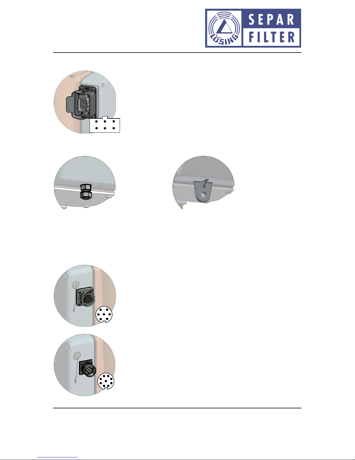
Heating voltage connection
Connector: Harting
Pin 1
Heating voltage (see operating voltage from the heater)
Pin 3
Heating voltage (see operating voltage from the heater)
Pin 5
Protective conductor
Separate protective earth terminal
Old revision (stud M8)
New revision (lug with hole 8,5 mm)
Control connector (available with Cannon or Hummel connector)
Cannon:
Hummel:
Connector
Cannon
Connector
Hummel
Pin A
Pin 1
24 VDC (for control electronics)
Pin B
Pin 2
GND
Pin C
Pin 3
24 VDC (for external main contactor)
Pin D
Pin 4
Switching output for main contactor
Pin E
Pin 5
Connection to 6 (F) when error
Pin F
Pin 6
Medium changer connection (status)
Pin G
Pin 7
Connection to 6 (F) when heating OK
Pin 8
Not used
Pin 9
Not used
3
5
4
6
1
2
A
C
D
B
F
G
E
6
8
1
7
3
2
5
4
9
Other manuals for SWK-2000
1
Table of contents
Other Separ Filter Water Filtration System manuals


Popular Water Filtration System manuals by other brands


Kinetico
Kinetico B Series owner's manual

Oase
Oase BioSmart 18000 operating instructions

Watts
Watts Lync WQ-AS Installation, operation and maintenance manual

GENERAL ECOLOGY
GENERAL ECOLOGY Seagull IV X-6 Installation and use guide

Alpine
Alpine PLG3500U owner's manual

American Plumber
American Plumber WFP3/4-10A Installation and operating manual