REVCON RHF User manual

Version 2/2023
Commisioing guide
Harmonic Filter RHF-Active
Software configuration guide

Content
1RHF-Active commissioning guide
Content
1. Important Information ............................................................................... 2
1.1 About the manual........................................................................................................................... 2
1.2 Terms and definitions..................................................................................................................... 2
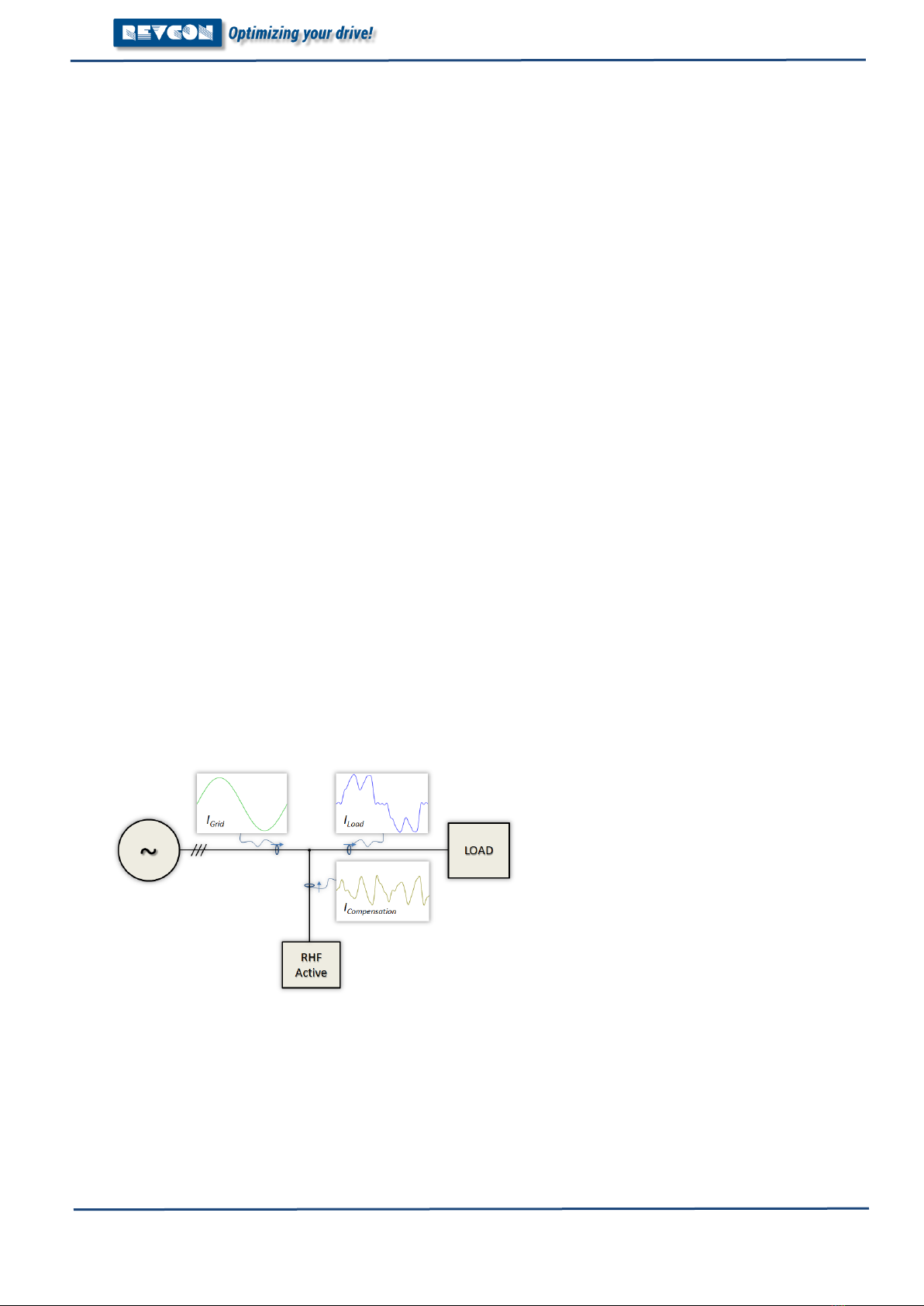
1.3 Working principle – RHF-Active...................................................................................................... 2
2. Connection................................................................................................. 4
2.1 Required hardware......................................................................................................................... 4
3. Home ......................................................................................................... 8
3.1 Home page ..................................................................................................................................... 8
4. Settings ...................................................................................................... 9
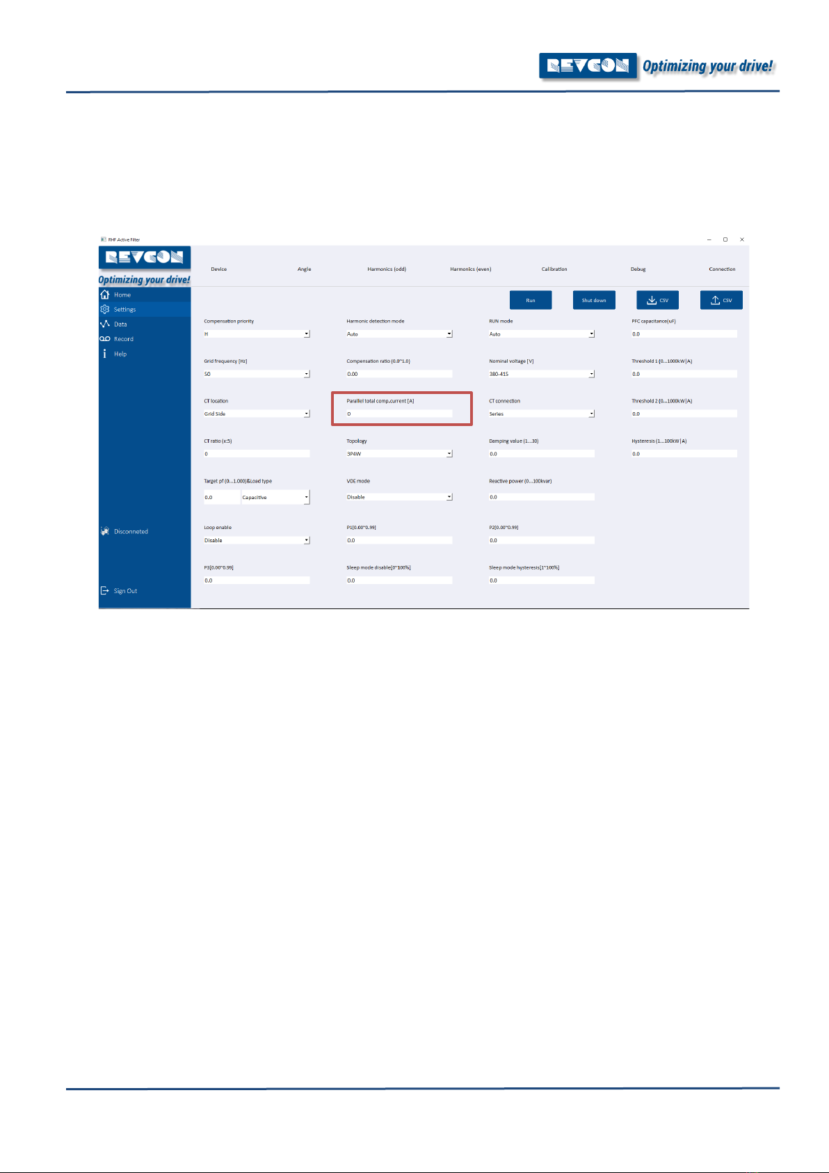
4.1 Settings – Device ............................................................................................................................ 9
4.2 Settings – Angle ............................................................................................................................ 12
4.3 Settings – Harmonics (odd) .......................................................................................................... 13
4.4 Settings – Harmonics (odd/even) – fine-tuning harmonics ......................................................... 14
4.5 Settings – Harmonics (even)......................................................................................................... 15
4.6 Settings – Calibration.................................................................................................................... 16
4.7 Settings – Debug........................................................................................................................... 17
4.8 Settings – Connection................................................................................................................... 18
5. Data ..........................................................................................................19
5.1 Data – Grid.................................................................................................................................... 19
4.2 Data – Load................................................................................................................................... 20
4.3 Data – Power ................................................................................................................................ 21
4.4 Data – Filter .................................................................................................................................. 22
4.5 Data – Filter .................................................................................................................................. 23
4.6 Data – I/O ..................................................................................................................................... 24
6. Record.......................................................................................................26
6.1 Record - Ongoing/cleared alerts .................................................................................................. 26
6.1 Possible alerts and troubleshooting............................................................................................. 27

1. Important Information
RHF-Active commisioning guide 2
1. Important Information
1.1 About the manual
This commissioning guide shall ensure help the commissioning of a REVCON RHF-Active and
explains the individual functions of the RHF-Active software and parameters. Commissioning of
active filter should be handled by an electrical engineers with experience in active filter
commissioning and they should have solid experience working with harmonics.
1.2 Terms and definitions
Filter module
For „Filter module REVCON RHF-Active“ the term „Filter module“ will be used.
Drive controller
For the frequency inverter which is used together with the power feedback unit in the following
the term „Controller“ is used
Drive system
For a drive system with harmonic filter, power feedback units, controller and other components
of the drive system in the following the term „Drive system“ is used.
1.3 Working principle – RHF-Active
In order to commission the active harmonic filter, a good understanding of the working principle
is mandatory.
The following picture is showing the basic topology and the working principle of the RHF-Active.
Active Harmonic Filters are parallel filter circuits injecting harmonics into the supply. These
Harmonics have phase shift of 180° compared to the harmonics in the system. Therefore, the
injected Harmonics are eliminating the Harmonics seen from the mains supply.

Content
3RHF-Active commissioning guide
The following picture helps to verify the principle.
The result of the above shown harmonics is 0. The harmonics from load side are compensated by the
RHF-Active injected harmonics. As a result, harmonics upstream of the RHF-Active will be low.
The RHF-Active will inject a harmonic current of same amplitude and frequency, but reverse angle into
the connection point. Therefore, the theoretical result of the THDi upstream of the RHF-Active is 0%,
assuming that the filter is sized for the full THC (Total Harmonic Current).
Nevertheless, the expected result is depending on many different factors such as:
-Grid-Load-Resonances - resonance frequency can typically not be fully eliminated.
-Measurement deviation – The true harmonic amplitude and angle is not the same as the
measured harmonic content (reduced by high accurate measurement).
-Filter accuracy – Even though the RHF-Active is based on the most accurate hardware topology,
100% accuracy is not possible. Therefore, there is always a deviation between measured value
and injected value.
-Load THDi value – The THDi is a ratio of harmonic current to fundamental current. When the
Load THDi high, this will result in higher THDi result after compensation.
-30
-20
-10
0
10
20
30
5 7 11 13
RHF-Active Load

2. Connection
RHF-Active commisioning guide 4
2. Connection
2.1 Required hardware
For connection of the RHF-Active, a RS485 to USB converter is required.
2.2 Software
For connection of the RHF-Active to the PC the latest RHF-Active PC software should be used.
During download of the software, please ensure your antivirus software is not changing the
name or delating the exe file: “RHF-Active-SiC.exe”. Execute this exe to start the software. The
following Login for easy access can be used:
Login: 01
Password: 010101
Higher access level can be requested from REVCON.
NOTE: While entering values in the RHF-Active configuration software, the values must be
confirmed by pressing enter! Without this step, the value will not be written into the RHF-Active.

Content
5RHF-Active commissioning guide
2.3Connection – PC to filter module
For connection of the RHF-Active to the PC the latest RHF-Active PC software should be used.
In order to establish the connection to the filter module. Got to: “Settings” → “Connection”
1. “Port Check”
2. Choose correct “serial port”
3. “Baud rate” should be set to 19200
4. “Connect” with either individual filter or system level (see chapter parallel connection)
5. Press “Connect”
6. Verify: “Disconnected” turns to green “Connected”

2. Connection
RHF-Active commisioning guide 6
2.4 Connection – Parallel setup
RHF-Active filters rated >55A are constellation of parallel setups. When ordered this way the
filters will be set for parallel operation by factory. Settings can be changed in system level. If the
compilation of active filters are changed, it can be necessary to follow the parallel setups.
Step one: Configure the MOBDUS address.
1. Connect RS485 connector to device 1 of your setup (other filters must not be connected)
2. Connect to filter as described in previous chapter.
3. Add “1” into “Device address”. Press enter.
4. Disconnect RS485 connector from device 1.
5. Connect RS485 connector to device 2 of your setup (other filters must not be connected)
6. “Connect” to filter.
7. Add “2” into “Device address”. Press enter.
8. Proceed for required number of parallel units.
After these steps, all filters can be connected via RS485 connection. Individual filters can be
addressed by using the filter selection menu.
Changes performed in “System” Level will result in changes on all connected filters. Changes
performed in 1-16 will result in changes on the equivalent filter with the corresponding Modbus
address 1-16.

2. Connection
7RHF-Active commissioning guide
Step two: Configure individual filters for parallel operation:
In order to run RHF-Active in parallel, the individual filters must be set to the correct total
compensation current connected (“Parallel total comp. Current [A]”).
This setting can be done in system mode.
E.g.
RHF-Active 220-480-50/60-20-A is an active filter for 220A. This is a compilation of 4 x RHF-
Active 55-480-50/60-20-A. The Total “Parallel total comp. Current [A]” is: 220.
RHF-Active 70-480-50/60-20-A is an active filter for 70A. This is a compilation of 1 x RHF-Active
55-480-50/60-20-A and 1 x RHF-Active 15-480-50/60-20-A. The Total “Parallel total comp.
Current [A]” is: 70.
RHF-Active 350-480-50/60-20-A is an active filter for 350A. This is a compilation of 2 x RHF-
Active 150-480-50/60-20-A and 1 x RHF-Active 100-480-50/60-20-A . The Total “Parallel total
comp. Current [A]” is: 350.

3. Home
RHF-Active commisioning guide 8
3. Home
3.1 Home page
The first page of the RHF-Active is “Home” This page gives an overview of considered
interesting values, such as “Voltage”, “Grid Power”, Grid current” and “Load current”
Run
Set the unit into operation
Shut down
Turn of operation
Clear fault
Delate fault (e.g. after EPO – Emergency Power Off).

4. Settings
9RHF-Active commissioning guide
4. Settings
4.1 Settings – Device
The Device settings are mayor function paramaters of the RHF-Active. It is recommended that
these paramters are only changed while RHF-Active is “Shut down”
Run
Set the unit into operation
Shut down
Turn of operation
↓CSV
(download) - Saves the current parameters into a CSV to be
stored on PC.
↑CSV
(upload) – Uploads a CSV parameter list into the machine.
Compensation Priority
H: Harmonic mitigation only
HR: Harmonic mitigation and fundamental reactive current
(Priority Harmonics)
HRU: Harmonic mitigation, fundamental reactive current, and
current unbalance (1. Priority Harmonics 2.Priority fundamental
reactive current)
Self aging: For factory use only!

4. Settings
RHF-Active commisioning guide 10
Harmonic detection
mode
This parameter changes the algorithm of the harmonic
compensation mode. Auto mode should be preferred.
Auto: optimum setting of individual harmonics will be searched
by the filter. Individual settings for individual harmonics will be
used as max values.
Manually: Harmonics will be mitigated in accordance to the
individual harmonics settings.
Completely: All harmonics will be mitigated independent of the
individual harmonics settings
RUN mode
Auto: Filter starting automatically when connected to power
supply. Recommended setup after commissioning for most
applications.
Manually: Filter can be started via PC software “Run” or by
external signal on In1. (10-24V high to start, 0V to Stop)
PFC capacitance
The RHF-Active can be used, as a hybrid system for reactive
power compensation on fundamental current (I1). In this mode,
the RHF-Active controls additional passive PFC equipment. The
value entered corresponds to the individual capacity of the
passive PFC circuit in µF.
Grid frequency
Grid frequency is detected by the software and can be changed
individually by this parameter. Will be reset after power of.
Compensation ratio
Limitation of harmonic mitigation. Can be used to move the
priory for harmonic mitigation in HR and HRU mode.
Nominal voltage
Grid voltage is detected by the software and can be changed
individually by this parameter. Will be reset after power of.
Threshold 1
Threshold for RHF-Hybrid setup. This will close the NO1 or NO2
contact at the specified kW value. This is used to bypass and
close the filter circuit in the RHF passive filter via contactor.
CT Location
Grid side: closed loop control. CT are located upstream of the
filter
Load side: open loop control. CT are located downstream of the
filter (recommended!)
Parallel total comp.
current
Value of total active filter connected in parallel (same CT signal)
CT connection
CT Connection for parallel operation of several RHF-Active with
one CT Signal.
Series: CT´s are in series (recommended!)
Parallel: CT´s are connected in parallel (not recommended!)
Threshold 2
Threshold for RHF-Hybrid setup. This will close the NO1 or NO2
contact at the specified kW value. This is used to bypass and
close a second filter circuit in the RHF passive filter via
contactor.
CT ratio
Ratio of CT (x:5). E.g. CT: 200A to 5A, enter 200
Topology
3P4W: For setups with 3 phase supply and neutral.
3P3W: For setups with symmetrical 3 phase supply.
Damping Value
Damping of current controller. Recommended:
“10” for 3P4W system.
“30” for 3P3W system with VFD typical spectrum.
“20” for 3P3W system with EC Fan or slim DC bus drive
spectrum.
Lower value corresponds to less damping in the compensation.

4. Settings
11 RHF-Active commissioning guide
Hysteresis
Hysteresis for the open and close of the Threshold 1 and 2 in
order to avoid frequent open and closing of the contact.
Target pf
Target for reactive current compensation. Can be set Capacitive
or Inductive. (leading or lagging current)
VDE mode
VDE Mode can be enabled if active filter is used with REVCON
Regen unit in order to reach the VDE-AR 4105
Reactive power
Reactive Power settings for VDE Mode in kvar
Loop enable
Not used. Default: Disable
P1
Not used. Default: 0.0
P2
Not used. Default: 0.0
P3
Not used. Default: 0.0
Sleep mode disable
This value will disable the sleep mode. Filter will start operation
once the initial value is reached. The parameter is linked to the
CT ratio. E.g. CT ratio is 200 and sleep mode disable is 10%.
The filter will start operation at 20A nominal load current.
Sleep mode hysteresis
Offset in % from sleep mode disable. E.g. CT ratio is 200A and
sleep mode disable is 10%. Sleep mode hysteresis is set to 5%.
Filter will start operation at 20A, and turn of at 10A.

4. Settings
RHF-Active commisioning guide 12
4.2 Settings – Angle
The RHF-Active is injecting harmonics of opposite angle, compared to the measured value. Deviation
between measured value and injected value can be adjusted in the “Angle” settings. Values are referring
to degree (2.20 correspond to an offset of 2.2° (injection angle 180°+2.2°)). Negative values are possible.
These settings can be changed during operation on the RHF-Active.
Run
Set the unit into operation
Shut down
Turn of operation
↓CSV
(download) - Saves the current parameters into a CSV to be
stored on PC.
↑CSV
(upload) – Uploads a CSV parameter list into the machine.
Fundamental angle
Angle offset of fundamental angle compensation.
Phase A angle
Angle offset of complete signal measured via L1.
Phase B angle
Angle offset of complete signal measured via L2.
Phase C angle
Angle offset of complete signal measured via L3.
3rd angle
Angle offset of 3rd harmonic for L1-L3.
n angle
Angle offset of n harmonic for L1-L3.
25th angle
Angle offset of 7th harmonic for L1-L3.

4. Settings
13 RHF-Active commissioning guide
4.3 Settings – Harmonics (odd)
The RHF-Active is injecting harmonics of same amplitude as measured value. Deviation between
measured value and injected value can be adjusted in the “Harmonics (odd)”.
Values are referring to a factor of the individual harmonic amplitude (1.05 correspond to compensation
of 105%). This setting is used to fine-tune the performance of the RHF-Active. These settings can be
changed during operation on the RHF-Active.
Run
Set the unit into operation
Shut down
Turn of operation
↓CSV
(download) - Saves the current parameters into a CSV to be
stored on PC.
↑CSV
(upload) – Uploads a CSV parameter list into the machine.
3rd
Compensation of the 3rd harmonic order as a factor. Values from
0.00-1.10 are allowed. (0-110% compensation current).
n
Compensation of the n harmonic order as a factor. Values from
0.00-1.10 are allowed. (0-110% compensation current).
61st
Compensation of the 61st harmonic order as a factor. Values
from 0.00-1.10 are allowed. (0-110% compensation current).

4. Settings
RHF-Active commisioning guide 14
4.4 Settings – Harmonics (odd/even) – fine-tuning harmonics
In order to achieve the best possible performance, fine-tuning of individual harmonics is recommend.
The following procedure can be used:
1. Install PQ-Analyser upstream of the RHF-Active.
2. Start RHF-Active and view result in bar graph mode.
3. Identify harmonic content on 5th Harmonic on PQ analyser or start with 3rd Harmonic if relevant
content (e.g. in 3P4W system)
4. Add +0.01 to the corresponding harmonic value in the RHF-Active software.
5. Review the result:
a. If harmonic content is less than before, move on to step 6.
b. If harmonic content is higher, move on to step 8.
6. Add +0.01 to the corresponding harmonic value in the RHF-Active software.
7. Review the result:
a. If harmonic content is less than before, repeat step 6.
b. If harmonic content is higher, insert previous value and move on to step 12.
8. Add -0.01 to the corresponding harmonic value in the RHF-Active software.
9. Review the result:
a. If harmonic content is less than before, move on to step 10.
b. If harmonic content is higher move back to initial value and move on to step 12.
10. Add -0.01 to the corresponding harmonic value in the RHF-Active software.
11. Review the result:
a. If harmonic content is less than before, repeat step 10.
b. If harmonic content is higher, insert previous value and move on to step 12.
12. Repeat steps 4-11 with next odd harmonic order until all harmonics are within the considered
limits.

4. Settings
15 RHF-Active commissioning guide
4.5 Settings – Harmonics (even)
The RHF-Active is injecting harmonics of same amplitude as measured value. Deviation between
measured value and injected value can be adjusted in the “Harmonics (even)”.
Values are referring to a factor of the individual harmonic amplitude (e.g. 1.05 correspond to
compensation of 105%). This setting is used to fine-tune the performance of the RHF-Active. These
settings can be changed during operation on the RHF-Active. Even order harmonics may be caused by
unbalance in the load. For symmetrical load, compensation of the even order harmonics should not be
required and settings of 0.00 is recommended.
Run
Set the unit into operation
Shut down
Turn of operation
↓CSV
(download) - Saves the current parameters into a CSV to be
stored on PC.
↑CSV
(upload) – Uploads a CSV parameter list into the machine.
2nd
Compensation of the 2nd harmonic order as a factor. Values from
0.00-1.10 are allowed. (0-110% compensation current).
n
Compensation of the n harmonic order as a factor. Values from
0.00-1.10 are allowed. (0-110% compensation current).
60th
Compensation of the 60st harmonic order as a factor. Values
from 0.00-1.10 are allowed. (0-110% compensation current).

4. Settings
RHF-Active commisioning guide 16
4.6 Settings – Calibration
The RHF-Active is injecting harmonics of same amplitude as measured value. Deviation between
measured value and injected value can be reduced by proper calibration of the CT. This step is made in
the factory, but in some occasions, this may be necessary on site.
For calibration, a very stable load current through the CT is required. The load should be between 60-
80% if the nominal CT load. Calibration of other than “Load current A/B/C” should only be made in the
factory. The calibration is made by the following steps:
1. Turn off the RHF-Active
2. Install PQ analyser or other accurate current measurement with detailed IRMS calculation.
Measurement should be in the same position as the CT connected to the RHF-Active.
3. Compare “load current” IRMS (Home) and measured current by the measurement device
connected (IRMS).
4. If a relevant deviation was found. Calibration may be required. Please note that all fine-tuning of
the RHF-Active filter will miss-tuned after the next step.
5. Enter the measured IRMS value from L1 into “Load current A”.
6. Enter the measured IRMS value from L2 into “Load current B” (required for 3P4W only / 3 CT
connected only).
7. Enter the measured IRMS value from L3 into “Load current C”.
8. Compare “load current” IRMS (Home) and measured current by the measurement device
connected (IRMS).
9. If a relevant deviation was found. New Calibration may be required. Repeat step 5-8.
Remark: Often the current changes with time (due to variation of mains voltage, temperature
etc.). Therefore this action is time critical. It is recommended to enter the measured current
immediately into the RHF-Active.

4. Settings
17 RHF-Active commissioning guide
4.7 Settings – Debug
The Debug page can give information on different MODBUS RTU address. This page is currently reserved
for factory use only.

4. Settings
RHF-Active commisioning guide 18
4.8 Settings – Connection
Port Check
Checks for available USB Devices.
Connect
Connects the PC Software to the RHF-Active if settings are
correct.
Disconnect
Disconnects the PC Software to the RHF-Active.
Serial Port
Shows available USB Devices. Choose device corresponding to
RS485-USB connector
Baud rate
Different available baud rates. Choose: 19200
Device address
Setting for individual MODBUS Address of RHF-Active (See
chapter 2.4 for details)
Connect (drop down
menu)
Choosing between individual RHF-Active (1-16) or system level.
During system level, several parallel RHF-Active will act as one
device. (See chapter 2.4 for details)

5. Data
19 RHF-Active commissioning guide
5. Data
5.1 Data – Grid
The Data-Grid page is showing voltage current waveforms of the grid side. This individual current and
voltage can be enabled and disabled using the check marks on the left side.
NOTE! For CT on load side, there is no measurements of the grid side current. The grid side current
should only be considered as a pproximation of the true current waveform.
Table of contents
Other REVCON Water Filtration System manuals
Popular Water Filtration System manuals by other brands

Waterwise
Waterwise 8800 User & care guide

Atlantic Ultraviolet
Atlantic Ultraviolet Mighty Pure MP16A owner's manual

Quincy Compressor
Quincy Compressor EWS 20 Instructions for installation and operation

HYDRALOOP
HYDRALOOP H300 User & installation manual

JRC
JRC NSVS1103 manual

GCTek
GCTek AlphaONE instructions