GENERAL ECOLOGY Seagull IV X-6 Operating manual

Installation Instructions
CONGRATULATIONS!You have just purchased a General
Ecology, Inc. SEAGULL®IV X-6 Water Purification System
employing the most advanced, effective and reliable
technology available. The features of this equipment are
indicated in product literature accompanying each Unit. It
is recommended that you briefly study this literature before
beginning your installation. Please note that the
SEAGULL®IV X-6 Unit features Top Mounted, Sweat-type
Copper Inlet and Outlet Adapter/Connectors that are
available in either ¾ or 1 inch sizes. Be sure you have the
proper size for your installation (normally ¾ inch for
residential applications).
Multiple Units can be installed in parallel to increase flow
rate (for industrial, commercial and special applications),
or in series for special requirements such as pre-filtration
followed by submicron microfiltration.
Figure 1
Installation is straightforward and is easily accomplished
by persons experienced in plumbing installation and the
sweating of copper pipe. Normally, only a tubing cutter,
soldering torch, ½" wrench and possibly a pair of channel
lock pliers are required. A ½" “deep” socket, in lieu of the
wrench, will facilitate V-clamp Nut removal and replacement
and is recommended.
Series Installation
SUPPLY (IN)
Use same pipe
sizes throughout.
Figure 1
SUPPLY (IN)
SERVICE (OUT)
SERVICE (OUT)
1 ½" LINE
Parallel Installation
Made in the USA
SEAGULL®IV X-6
DRINKING WATER
PURIFICATION
SYSTEM
INSTALLATION AND
PRODUCT USE GUIDE

SEAGULL®IV X-6 Parts List and Dimensions
AssemblyInstructions
should be applied to center Port O-Rings of Housing Cover
before aligning it with the Cartridge Module.
7. Center the Cover on the Module while aligning it with the
Bowl Flange and press down into position.
8. Install V-clamp and tighten while lightly tapping the outside
of the V-clamp outside the bolt. A light coating of petroleum
jelly applied to the insides of the V segments will ease
the Clamp installation.
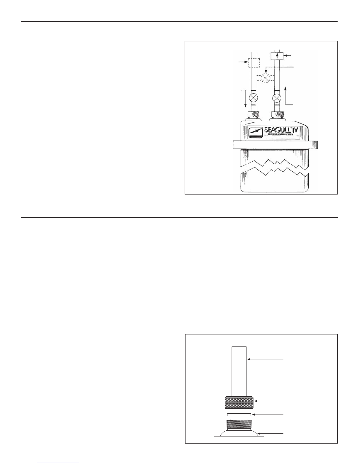
9. Note the Unit Cover’s Supply (INLET) Port and Service
(OUTLET) Port. On all General Ecology stainless steel
Units the Port closest to the side is the Supply (INLET)
Port and the center Port is the Service (OUTLET) Port.
1. Remove the stainless steel Housing and the Cartridge
Module from the package.
2. Remove the V-band that secures the Housing Cover and
Bowl by removing ½" Nut with a wrench or ½" deep socket.
3. Carefully raise the Cover, being careful not to dent or cut
the Bowl Flange, nor allow dirt on any of the Gaskets.
4. Lower the Cartridge Module into the Bowl until it sits on
top of the Rubber Pedestal.
5. Be sure Gaskets are clean and free of cuts and other
potential leak paths.
6. For ease of installation, a light coating of petroleum jelly
EquipmentPlacement
The SEAGULL®IV X-6 Unit should be level and should have
adequate vertical clearance to permit the three (3) Dielectric
Positioning Pads to be positioned under each Unit.It is important
to use these Pads to allow vertical clearance for the Unit to
clear the Inlet and Outlet Connectors during servicing.
Additionally, the Pads eliminate potential electrical interface
between the Unit and the floor.
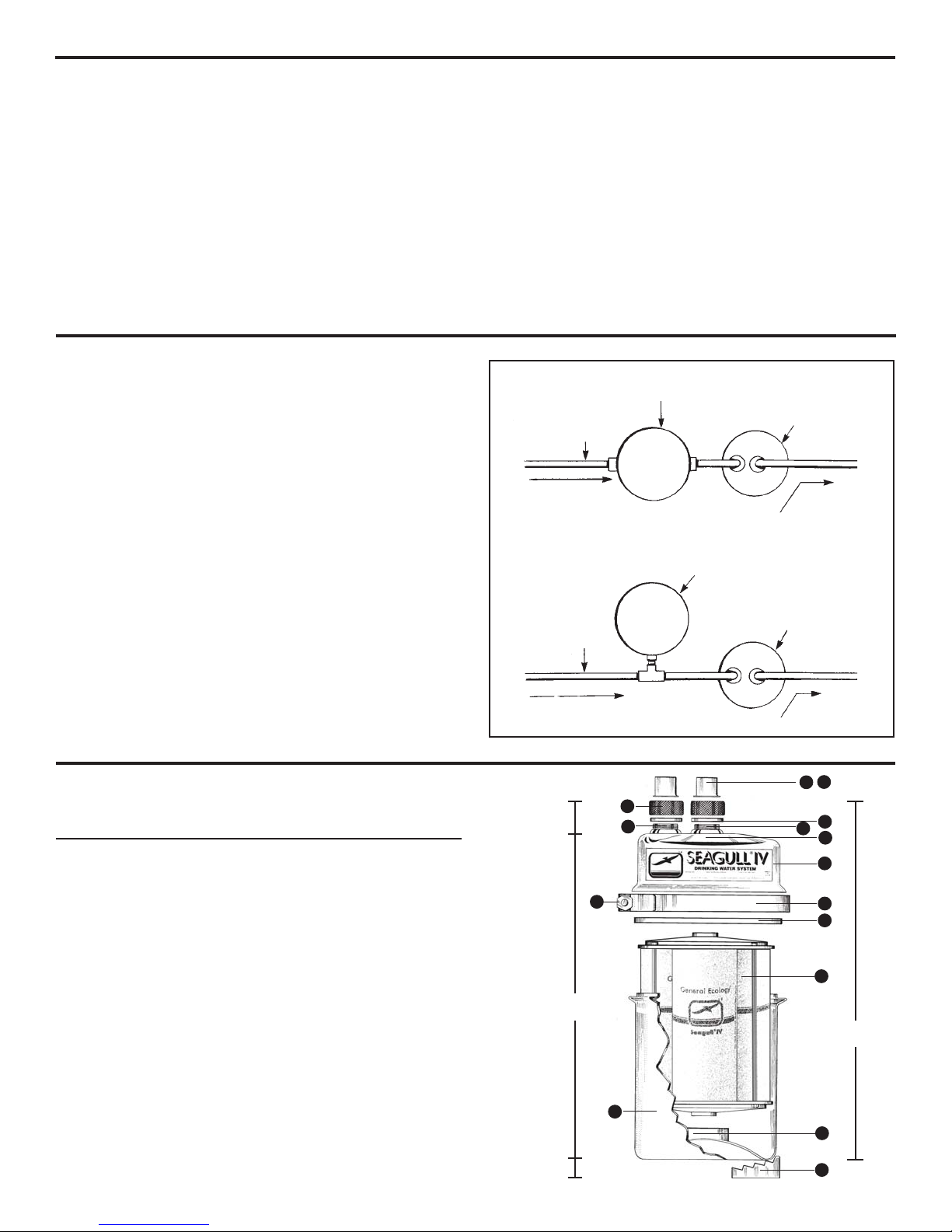
The Unit should always be placed on the Service (OUTLET)
side, rather than the Supply (INLET) side, of the air pressure
tanks used with on-site water supplies. See
Figure 2
.
After deciding on placement of the Unit, it is recommended
that appropriate fittings such as valves, nipples, elbows, etc.,
be “dry fit” to be sure of proper positioning, and to double-
check the routing, proper lengths and other factors that will
assure a workmanlike job. Do not strap copper tubing rigidly in
place near the Unit. Allowing tubing to flex slightly will reduce
possibilities of uneven strain at the Inlet and Outlet Connections.
Because of the special Inlet and Outlet Connectors, union joints
usually are not needed.
SERVICE
(OUT)
1 Cover 1 100200
2 Bowl 1 100300
3 V-Clamp 1 100400
4 Housing Gasket 1 100401
5 Inlet Port 1 100411
6 Outlet Port 1 100412
7 Module Seal O-Rings (Internal) 2 100414
8 Knurled Closure Nuts 2 100415
9 Closure Nut Gaskets 2 100416
10 3/4" Sweat Adapters 2 100417
11 1" Sweat Adapters 2 100418
12 Pedestal Assembly 1 100424
13 Dielectric Positioning Pads 3 100421
14 V-Clamp Hex Nut 1 100402
15 RS-6SG Module 1 100501
No. Description Qty. Part No.
SPARK-L-PURE®
METERING
PUMP
(If Required)
SUPPLY (IN)
"TEE" Pressure Tank Installation
SPARK-L-PURE®
METERING
PUMP
(If Required)
SUPPLY (IN)
Figure 2
SERVICE
(OUT)
SERVICE
(OUT)
IN/OUT Pressure Tank Installation
9
6
1
3
4
12
13
7
10 11
8
5
15
16.25" *
(38.1 cm)
1.25" *
(3.2 cm)
15" *
(38.1 cm)
1.25" *
(3.2 cm) * Assembled Dimensions
14
2

InstallationConsiderations
Valves should be placed in series with the Supply (INLET)
and Service (OUTLET) Lines as shown in
Figure 3
. A Flow
Controller, if necessary, should be placed in the Supply Line
to help limit flow surges due to trapped air and other possible
causes. A Check Valve should be placed in the Service Line
to protect the Unit from backpressure surges. It may also be
desirable to place a third (By-pass) Valve directly between
the Inlet and Outlet Lines as indicated in Figure 3, but we
recommend that this not be done if highest reliability against
by-pass is important.
A By-Pass Valve should be installed only if contamination of
the Service Lines is not a potential problem.The purpose is
to allow water to bypass the Unit, if desired, by closing the
Inlet and Outlet Lines, and opening the By-pass.
The SEAGULL®IV X-6 Unit is compact, relatively lightweight
and is easily disconnected from the plumbing lines. It is not
necessary to service the Unit in place; for convenience, it
can be carried to a nearby sink, floor drain, or even outside.
Adequate clearance should be provided around the installed
Unit for ease of movement and to allow servicing on other
pieces of equipment when necessary. Obviously, the Unit
should not be allowed to freeze.
1. Select location and position Unit as desired.
2. Close Supply and Service Valves to isolate the plumbing
at the installation point.
3. Dry-fit the plumbing fittings and pieces necessary to install
the Unit and cut or unthread existing plumbing lines as
appropriate.
4. Solder all joints. Do not allow excess heat to reach any
seals or gaskets and be sure solder does not coat the
sealing faces of the Sweat Adapters nor reach the ball or
seal of any valves.
5. In order to avoid the possibility of connecting the
SEAGULL®IV X-6 Unit in the reverse direction, be sure
to label the Supply (INLET) and Service (OUTLET)
pipes.
6. Position the SEAGULL®IV X-6 Unit, and start the threads
of the Knurled Closure Nuts. Be sure to place the Closure
Nut Gaskets in the order shown in Figure 4. Place the
Positioning Pads underneath the Unit and raise it to the
proper elevation to eliminate strain on the Inlet and Outlet
Ports, and snugly finger tighten the Inlet Port Nut only
at this time.
7.
Slowly
open the Supply Line Valve allowing water to enter
the Unit. Trapped air will exhaust through the loosely
connected Outlet Port until the Unit fills.When water starts
to flow from the Outlet:
a. Close the Inlet Valve.
b. Snugly tighten the Outlet Closure Nut.
c. Open the Outlet Valve.
d. Reopen the Inlet Valve to place the SEAGULL®IV X-6
Unit in service.
8. Check carefully for leaks or seepage around any of the
joints or connections and correct as necessary.
9. Allow water to run for three to five minutes to remove air
and particles from the new module.
InstallationInstructions
FLOW
CONTROLLER
CHECK
VALVE
BY-PASS
VALVE
INLET
SUPPLY
(IN) OUTLET
SUPPLY
(OUT)
Figure 4
SWEAT
ADAPTER
KNURLED
CLOSURE NUT
CLOSURE NUT
GASKET
PORT
Figure 3

ServiceInstructions
The SEAGULL®IV X-6 Purification Unit, furnished with General Ecology, Inc.’s RS-6SG Cartridge Module, should require
little or no service other than an occasional Module replacement. The need for changing the Module will be apparent from
an obviously reduced flow rate due to clogging. Service should be accomplished by the following procedure.
IMPORTANT: In order to avoid reinstalling the Unit in the reverse direction, the Inlet and Outlet Pipes should be labeled
prior to disconnecting the unit. On all General Ecology stainless steel Pressure Vessels, the Port closest to the Vessel
Cover’s side is the Supply (INLET) Port and the center Port is the Service (OUTLET) Port.
Made in the USA
Disassembly
Removing Module from Unit:
1. Close Supply and Service Line Valves, loosen brass
Closure Nuts and gradually remove Dielectric Positioning
Pads to lower Unit to supporting surface.
2. Place Unit over drain or a container to catch excess
water as the V-clamp is removed, and remove V-clamp.
3. Carefully raise the Cover from the Unit and remove the
Cartridge Module. (We recommend the use of rubber
gloves to protect the skin from direct contact with the
potential concentration of impurities that may be on the
outside of the Cartridge Module.) Dump excess water
from the Bowl and rinse clean. Be careful not to dent or
cut the Bowl Flange, nor cut, nor allow dirt on any of the
Gaskets.
4. Be sure the Rubber Pedestal is properly in place on the
raised center of the Bowl bottom.
5. Be sure Gaskets are clean and free of cuts and other
potential leak paths.
6. For ease of installation a light coating of petroleum jelly
should be applied to center port O-rings of Housing
Cover before aligning it with the Cartridge Module.
7. Lower new RS-6SG cartridge module into bowl.
8. Center the Cover on the Module while aligning it with
the Bowl Flange and press down into position.
9. Install V-clamp and tighten (do not overtighten) while
lightly tapping the outside of the V-clamp outside the
bolt. A light coating of petroleum jelly applied to the
insides of the V segments will ease clamp installation. A
small amount of anti-seize compound should be applied
to the V-clamp bolt.
Reinstallation
Placing the Unit back in service:
1. Reposition the Unit per initial installation, being careful
to replace the Closure Nut Gaskets properly and to
position the Unit to eliminate strain on the Service and
Supply Lines. Finger tighten the Inlet Port Nut only at
this time.
2.
Slowly
open the Supply Line Valve allowing water to
enter the Unit. Trapped air will exhaust through the
loosely connected Outlet Port until the Unit fills. When
water starts to flow from the Outlet:
a. Close the Inlet Valve.
b. Snugly tighten the Outlet Closure Nut.
c. Open the Outlet Valve.
d. Reopen the Inlet Valve to place the
SEAGULL®IV X-6 Unit in service.
3. Allow water to run for three to five minutes to remove
air and particles from the new module.
200123
©1996,General Ecology,Inc. revised 9/02 ®, ™TrademarksofGeneral Ecology,Inc.
(610)363-7900 - fax (610)363-0412
www.generalecology.com
QUESTIONS?
Call 1-800-441-8166
in USA/Canada
for Customer Service
OUTLET PORT
V-CLAMP
MODULE
DIELECTRIC PAD
HOUSING COVER
V-CLAMP NUT
HOUSING GASKET
HOUSING BOWL
Table of contents
Other GENERAL ECOLOGY Water Filtration System manuals
Popular Water Filtration System manuals by other brands

Toshiba
Toshiba TWP-N1861UUFKW instruction manual

Paccar
Paccar MX-13 EPA 2017 Service manual

Donaldson
Donaldson Ultrafilter DF-T0050 Operation manual

Sears
Sears 390.160500 owner's manual

CALEFFI
CALEFFI DISCAL 5517 Series Installation, commissioning and servicing instructions

Kemppi
Kemppi PFU 210e operating manual