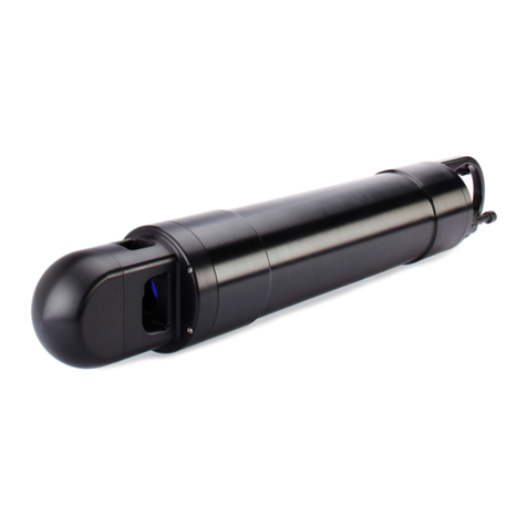
Sequoia LISST-VSF User manual


LISST-VSF
FEATURES:
In-situ measurements of P11 (VSF), P12 and P22 elements of the scattering Mueller
matrix from 0.1-155o(nominal) in water
VSF (P11) only at small angles, 0.1 to 15o (nominal) in 32 logarithmic steps in angles
Integration of 0.1-155oVSF provides a good estimate of total scattering coefficient b.
Beam attenuation measured with LISST-100X optics.
Roving EyeballTM optics permit 1oresolution in scattering angles between 15 -155o
Approximately 4 sec per measurement set [involves 2 turns of Eyeball with vertical,
and horizontal polarized laser].
Daylight rejection by laser modulation.
Data from small and large angles in a single data stream, including depth,
temperature, date and time.
This document is copyrighted by SEQUOIA SCIENTFIC, INC.


SPECIFICATIONS:
Parameters measured
Small-angle VSF in 32 log-spaced angles, from 0.1 to 15o(nominal)
VSF, P12 and P22 over 15-150oin 1osteps (nominal)
Temperature from –5° to 50°C with 10 mdeg resolution
Operational depth (50 m max depth @ 8 cm resolution)
Operating Concentration range
Beam attenuation from 0.13 to 20 m-1 (based on >=30% transmission)
Technology
Fiber Coupled TE-cooled Laser Diode @ 515 nm
Ring Detector for small-angle VSF
Roving Eyeball and PMT for 15-150o(nominal)
Mechanical and Electrical
LISST-VSF Instrument
Dimensions 13.3 cm (5.25”) diameter, 114.0 cm (44.9”) L
Weight: 15.6 kg (34.4 lbs) in air; in water TBD
Depth rating: 300 m survival depth (50 m operational depth)
External power input: 12VDC @ 5A, min 9VDC, max 20VDC
Sampling rate: 4 seconds for a full measurement of P11, P12, P22
Power drain: 700 mA measuring / 170mA quiescent
Data storage: 128GB, equivalent to 40,000? measurements
Battery Housing
Dimensions 13.3 cm (5.25”) diameter, 71.1 cm (28.0”) L
Weight: 10.3 kg (22.8 lbs]) in air; in water TBD
Capacity: 14.8V, 39 A-hr.


Welcome to the LISST-VSF!
Using this manual
This manual is divided into two sections.
Section One contains an introduction to the LISST-VSF
instrument and the principles of its operation.
Section Two provides detailed instructions for operation
Appendices provide further details …
Instrument Specific Constants
These are included in a MATLAB file, named
Cal_Factors_xxxx.mat, where xxxx is the serial number of your
instrument.
Technical assistance
For technical assistance please contact your local Distributor or
Sequoia. Please be sure to include the instrument Serial
Number with any correspondence.


Waste Electrical and Electronic Equipment
Smaltimento di apparecchiature elettriche ed elettroniche da rottamare


Table of Contents
SECTION I: LISST-VSF INSTRUMENT........................................................................................13
I.1 INTRODUCTION................................................................................................................13
I.2 HOW IT ALL WORKS........................................................................................................17
I.3 GENERAL PRECAUTIONS .................................................................................................21
I.4 QUICK START..................................................................................................................22
SECTION II: OPERATION.............................................................................................................27
II.1 INSTRUMENT MOUNTING,STORAGE AND MAINTENANCE....................................................28
II.2 CHARGING AND CONNECTING THE LITHIUM-ION BATTERY PACK ........................................30
II.3 BENCH TESTING AND COLLECTING BACKGROUND DATA....................................................32
II.4 OFFLOADING AND ERASING DATA FILES FROM INSTRUMENT..............................................35
II.5 RECORDING AND STORING A SAMPLE DATA FILE ..............................................................38
II.6 DATA PROCESSING .........................................................................................................40
SECTION III INSTRUMENT PROGRAMMING AND COMMAND DETAILS .............................54
III.1 PROGRAMMED OPERATION FOR FIELD OR LABORATORY USE............................................55
III.2 LISST-VSF COMMAND SUMMARY...................................................................................58
APPENDIX A: DETAILS OF LISST-VSF INSTRUMENT ............................................................68
APPENDIX B: METHOD OF EXTRACTING P11, P12 AND P22.................................................72
APPENDIX C: MATLAB SOFTWARE..........................................................................................75
APPENDIX D: OBSERVATION ANGLES, DATA STORAGE FORMAT AND VARIABLE NAMES
.......................................................................................................................................................77
APPENDIX E: CONNECTOR PINOUTS FOR LISST-VSF..........................................................80
APPENDIX H: LISST-VSF ACCESSORIES ................................................................................83
WARRANTY ..................................................................................................................................84


LISST-VSF User’s Guide 13
Section I: LISST-VSF Instrument
I.1 Introduction
Thank you for purchasing a LISST-VSF instrument, and congratulations on
your new purchase.
The LISST-VSF delivers a powerful suite of measurements for marine optical
scientists, all from one package. It delivers the Volume Scattering Function
(VSF) from small forward angles to wide angles, depolarization parameters,
and the beam attenuation coefficient c. An excellent estimate of the beam
scattering coefficient b, and by difference, the beam absorption coefficient a
can also be derived from the data. All properties are measured at a laser
wavelength of 532nm. The forward angles in water, from 0.0936 to 15.05, at
which VSF is measured are spaced logarithmically. The intermediate and
large angles (>15-deg) are linear, with 1-deg resolution. Because of the high
angular resolution, this instrument permits examination of enhanced
scattering by bubbles in the ~80-deg region.
Light Scattering
and VSF
The Volume Scattering Function (VSF) describes the distribution of scattered
light energy as a function of scattering angle. VSF is defined for unpolarized
light source and no discrimination of polarization in the scattered light.
However, scattering of light by particles always produces changes in
polarization state of the scattered rays. The state of polarization is described
by the Stokes vector I, with elements I,Q,U,V. The Stokes vector of the
scattered light and that of the incident light Iiare related through a matrix
product:
Is= P Ii
where P is the scattering Mueller matrix. P is a 4 x 4 matrix. It contains
information regarding particle scattering characteristics. The elements of P
are often denoted by Pij . The first element, P11 is identical to the volume
scattering function, VSF. Elements [1,2] and [2,2] relate to changes in the
linear polarization properties I and Q. For example, element P12 produces
depolarization. Element P22 is known to be an indicator of sphericity of
particles; so that P22 =1 everywhere implies that particles are spheres. With
the LISST-VSF, it is assumed that symmetry forces elements P13 and P14 to
zero, and that P12 and P21 are equal. Thus only 3 unknown are produced: P11,
P12, and P22,
At small forward angles, scattered light maintains its original polarization, so
that depolarization is small. This instrument does not measure depolarization
at angles smaller than 15o, because there the VSF is measured by a set of
ring detectors, identical to our familiar LISST-100X instrument. A different
instrument, LISST-Stokes has been developed for small-angle depolarization
studies.

14 LISST-VSF User’s Guide
Theory and
Mathematical
Description
Appendix A and B provide detailed description of optics of the instrument,
and of data processing method. Appendix C describes MATLAB data
processing functions. If data are good, a single command make_P processes
a set of files and produces elements of the P matrix, together with beam
attenuation and scattering coefficients. The function name make_P derives
from the scattering matrix P.
Instrument
Overview
The LISST-VSF instrument employs two optical systems which combine to
produce the full VSF. The small angle measurements (<15o) are done with
ring detectors, identical to our LISST-100X instrument. We will often refer to
data collected with these detectors as ring data, or rings data. Scattering at
larger angles (>15o) is measured using a rotating ‘eyeball’ (see photo on
opposing page). This data is referred to as eyeball data.
For ring data collection optics, please refer to details in one of several
publications (e.g. Agrawal & Pottsmith, 2000; included on the ship disk). A
simplified explanation of the eyeball optics for large-angle measurements is
offered here.
Typical volume scattering function sensors, or for polarization studies, typical
polarimeters observe a common sample volume with a multiple set of
detectors. In some of these systems, a single viewing telescope rotates
around the sample volume. The former system can only have a small number
of detectors, and each needs to be carefully calibrated. In the latter, rotating a
telescope requires cumbersome and slow mechanical systems that don’t lend
themselves to deep submerged usage. For these reasons, the present
instrument employs a rotating eyeball. Instead of viewing a common sample
volume, the eyeball scans the length of a laser beam, thus obtaining angular
information.
In the LISST-VSF instrument, the scattered light entering the eyeball is split
into its two polarization components, and each is sensed with a dedicated
photomultiplier (PMT). A set of measurements comprises the recording of
these two PMT outputs over 2 rotations of the eyeball. Each rotation is for a
fixed polarization of the laser; e.g. the first rotation is with perpendicular laser
polarized, and a second rotation is with parallel polarization. To rotate laser
polarization between eyeball turns, a half-wave plate is mechanically inserted
in the laser beam before it enters water. Data are stored in a single datafile
that combines rings and eyeball data.
The small eyeball makes the LISST-VSF instrument compact, autonomous,
and manageable underwater. As a result, this instrument may be left on a
tripod or mooring.
As explained in Appendix B, due to the rotating eyeball receiver, the stored
scattered light signals are a mix of the 3 parameters P11, P12 and P22. The
convenience of the eyeball thus involves a price –solving for these quantities.
We provide software to perform this function. For details, please see
Appendix C.

LISST-VSF User’s Guide 15
Electro-Optic
Components
The instrument employs a single 515nm TE-cooled diode laser for both optical
systems –rings and eyeball optics. To reject ambient light, the beam is
modulated at ~3 kHz. Two miniature, compact PMT’s are used to sense
scattered light. Electronics control the gain of these two PMT’s. The gain can
be adjusted with software commands. The output of PMT’s is digitized and
stored in data files. See Appendix B.
Depth and
Temperature
Sensors
The depth sensor is mounted to the instrument connector endcap. The
temperature sensor is also thermally bonded to this endcap. Please note that
the temperature sensor is therefore slow.
Communication
A cable is provided to connect the underwater connector on the instrument
endcap to a PC. Communication is at 9600baud, except when downloading
data, it automatically switches to 115Kbaud.
Internals
The cylindrical case with the flat endcap contains all the transmitting optics
and the 2 PMT’s. This includes the laser, a beam-expander, the polarization
rotator, and laser power (output) sensor (called Laser Reference throughout
this manual). The cylindrical case with the connector endcap contains the
small-angle measuring ring-detector optics, i.e. a 50-mm focal length lens, the
ring-detectors with its built-in sensor for laser power transmitted through water
(called Transmission sensor throughout) and related electronics. The space
around the eyeball in the middle is the test section, or the sample volume. The
water being measured is the water in this space. For laboratory work, you will
form a test chamber to hold water around the eyeball.
Two pressure windows can be seen on the two cases on either side of the
eyeball. One of these windows is clear. This is the transmit side window. The
other is dark. The dark window has an ND 1 filter cemented to it. This filter
reduces backscatter (glow) from optics on the small-angle optics side,
permitting measurements with the eyeball to about 155°.
A scheduling computer is placed alongside eyeball electronics.
Communication with this computer is over a serial line. The LISST-VSF
instrument can be programmed from a PC to execute a specific data
collection sequence. Software for programming the instrument and recovery
of data is provided. Data download is also carried out using the provided
software.
Measurement
Section
The eyeball is set to one side of the sample volume. This positioning permits
the eyeball to view scattering from about 10oonward to about 155°. The data
storage electronics are programmed to start capturing scattered light data
when the eyeball is positioned to view 5o scattering. (The precise angle varies
from instrument to instrument due to the setting of the optical encoder. The
offset in this angle is included in your calibration files). Ring detectors and the
eyeball, both cover the 5-15-degree scattering angle range. The overlap
permits calibrating the eyeball data with the outermost ring detector, thus
providing absolute calibration for photomultiplier signals. The 5-15 degree
range of data from the eyeball also includes the laser spot on the transmit
window. This spot glows brightly, thus offering a fixed target to further
calibrate/verify eyeball viewing angles.

16 LISST-VSF User’s Guide
The rectangular box below the eyeball in the photo is the housing for the
optical encoder which keeps track of eyeball angular position.
Figure 1 –In laboratory work, make sure the rectangular box is at top!
Laboratory and
Field Use
The instrument can be used in the laboratory or in the field. It can be operated
with an External Power Supply, or using the supplied rechargeable battery.
In battery-powered field usage, the instrument can be used from a wire in a
profiling mode, or it can be mounted on a tripod or mooring for a time-series
observation.
NEVER INSERT ANYTHING REFLECTIVE IN THIS SPACE. THE LASER
POWER IS APPROXIMATELY 10mW. IT WILL DAMAGE EYES.
The windows and endcap faces should be clean if doing laboratory work. If
deploying in the ocean, make sure both windows are clean. Use lens cleaner
or soap and water. DO NOT USE ABRASIVE CLEANERS.
Rechargeable Li-
Ion Battery Pack
The instrument power source is a rechargeable lithium pack. With all systems
on, the instrument draws about 0.7 A current. The fully charged battery can
power continuous operation of the instrument for up to ~40 hours. The
instrument checks the state of battery before capturing each set of data. If the
battery is low, a graceful shutdown is executed.
A battery charger is provided. While the battery is being charged, it cannot
power the instrument.
A separate external power supply, with an underwater connector that mates
with the instrument housing is provided for use in the laboratory.

LISST-VSF User’s Guide 17
I.2 How It All Works
Overview
After connecting power (battery or external power) and the communications
cable, the instrument becomes ready for operation. When commanded to
capture data, the following sequence happens: the laser is turned on for a
period to reach stable power. beam emerges from the transmit window and
the eyeball starts rotating. Each rotation takes about 2 seconds. During this
time eyeball data are captured. The sequence is as follows: beginning when
the optical encoder reads 15-degrees, the two PMT data are captured at 1-
degree intervals. Between 15 degree and 50-degrees of eyeball position, the
laser is dimmed by the laser controller. This is done because this scattering is
stronger; dimming keeps it within the PMT dynamic range. At 51 degrees
encoder position laser power is returned to full. Eyeball data are recorded
from the start angle for a specified number of angles, typically 150.
Ambient Light
Rejection
The eyeball continues the ‘blind’ part of its rotation. During this time, rings
data are captured. After ring data have been captured, the combined ring and
eyeball data are written to data file. Immediately, a half-wave plate is inserted
in the laser beam, so that during the next turn, PMT’s data would be captured
with laser polarization rotated by 90o. During the time allocated for the half-
wave plate insertion and settling of its mechanism (see figure), the laser is
turned off briefly to capture an ambient light background from rings. The cycle
repeats for the second rotation, only now the half-wave plate is removed. This
is illustrated in Fig.2.
.
Figure 2 –Laser power through 1 set of 2 rotations (shading shows laser
modulation during eyeball portion of data capture), HW is half-wave plate to
rotate polarization of laser, Note that laser power is reduced for the 5-50o part
of eyeball data capture, and laser is extinguished to read dark rings (ambient
light on rings) after activating HW.
Also stored in each rotation are auxiliary parameters - depth and temperature,
battery voltage, and date and time.
Each data set requires two rotations of the eyeball. The number of sets of
data is controlled from the command window or from the operating modes
menu. This is described in later chapters.
Black Glass
Receive Window
Why is an ND filter used on the small-angle optics window? This is because
internal glow from the small-angle optics contaminates particle scattering at
large angles, i.e. when the eyeball is viewing scattering at around 130oor
greater. The ND filter attenuates the glow.

18 LISST-VSF User’s Guide
Background
Light
Measurement
As with the LISST-100X instrument, so also with this instrument, a
background measurement is necessary. Background light for ring detectors
originates as scattering from optical surfaces. For eyeball data, background
light from scattering by water itself can be significant. Ambient light does not
contribute to background as it is rejected by laser chopping. A background
reading is required before any data collection. The background is measured
with flitered clean water in the sample volume. The measured background is
subtracted from particle data in data processing.
Dynamic Range
Challenge
Changing PMT
sensitivity
Because the VSF typically requires a wide dynamic range, it is not reasonable
to build a fully general purpose system. By using a combination of 12-bit A/D
for PMT outputs, and a factor of ~25 extension of the upper limit on scattered
light by dimming the laser at small scattering angles, we achieve about 16 bits
dynamic range. This is sometimes not sufficient. If so, it is possible to
increase or decrease sensitivity of PMT’s by changing the control voltage.
This is possible from the command window. The instrument is shipped with a
setting that is found suitable by us. Because saturation of the A/D is possible,
we recommend that you always view the raw data and look for saturation. A
function view_rawfile is provided for this purpose.
PMT sensitivity may be changed from the Terminal Window by typing
~c
The instrument will display a range of settings. Just hit enter for all, until the
PMT setting is displayed. Move it up or down 50 counts at a time to,
respectively, increase or decrease sensitivity.
Low Battery
Cutoff
The instrument checks for low-battery during sampling. If the battery is low, it
shuts off the high-current components such as the eyeball motor and laser in
an orderly fashion. When shut off in this mode, notification is printed to the
communications port, and residual battery power is used to return the system
to the command prompt.
Excess Depth
Shut Off
The instrument, when deployed in profiling mode, automatically checks for
depth exceeding maximum permissible for eyeball operation. If the critical
depth is exceeded, the eyeball is powered down and data collection pauses
until depth is again within specifications.
Data Processing
Data processing is performed in MATLAB. Software is provided to perform
these functions: (i)view any data file or background file with view_rawfile, (ii)
construct a mean background file from recently acquired background (pure
water) data, with make_zsc, and, finally, (iii) to produce the desired end
result: P11, P12, and P22, beam_c and beam_b with make_P. For convenience,
a few other functions are provided, e.g. to simulate eyeball data from Mie
theory. The expected measurement from, say, single size polystyrene beads
can be computed using this function for comparison with actual data.
Appendix B explains the methods. A listing of provided functions is in
Appendix C. The use of MATLAB permits flexibility to the scientific user.
LISST-VSF User’s Guide 19
A Tweak-able
Parameter
The relative gain of the two photomultipliers is required in solving for P11 etc.
This quantity cannot be reliably measured directly. Fortunately, the outputs of
the two PMT’s are theoretically exactly equal at scattering angles of 45oand
135o [see Appendix B, Eq.2b]. This permits estimating this ratio, which we call
from the data.However, error in estimation of can result in spikes in
estimates of P22. Thus, adjusting may be required. The value of at which
the spikes are minimized is relatively easy to find.
It is not correct to use the same value of at all times since it will depend on
PMT voltage, and we do not know if it drifts significantly over time.
NOTE: A version of the LISST-VSF MATLAB software tools that allows
simple modification of during data processing is under development!
A Quick Look at
End Results
For details on data processing, see the following Data Processing Overview
section.
If all goes well, you should see a composite VSF as shown below: a log-log
plot and a semi-log plot. Note that when working with small particles, the VSF
at the smallest angles (below left) may not be smooth. This is because the
amount of light on the smallest ring-detectors is very small, hence noisy. The
example below shows 10 sets (curves) from 1.6 micron polystyrene beads.
Figure 3 –Laboratory data from 1.6 micron polystyrene beads.
In general, field work will not produce such difficulty with smallest angles. If
you see this difficulty, and if turbulent scintillation is unlikely, it is possible to
use symmetry and flatten the curves. We make this suggestion only. Please
use your discretion on what is reasonable.

20 LISST-VSF User’s Guide
The software will also produce a display of P12, as well as an estimate of P22
which has a problem around 45 and 135-degrees, explained in Appendix B.
P22 is unity for spherical particles, which the example below shows
reasonably.
The processed data is summarized in a 2x2 plot containing the P11, P12, P22 as
well as the near-forward VSF derived from the ring detectors.
Figure 4 –Summary of LISST-VSF processed data
See Appendix B for explanation of spikes in result and how to minimize
them.
050 100 150
10-2
10-1
100
101
Angle [deg]
Eyeball P11 [m-1 sr-1]
10-2 100102
100
101
102
103
Angle [deg]
Near-forward VSF [m-1 sr-1]
050 100 150
-0.5
0
0.5
1
Angle [deg]
Eyeball P12 [m-1 sr-1]
50 100 150
-1
0
1
2
3
Angle [deg]
Eyeball P22 [m-1 sr-1]
Other manuals for LISST-VSF
1
Table of contents
Other Sequoia Measuring Instrument manuals

Sequoia
Sequoia LISST-VSF User manual

Sequoia
Sequoia LISST-Infinite User manual

Sequoia
Sequoia LISST-200X User manual

Sequoia
Sequoia LISST-Deep User manual

Sequoia
Sequoia LISST-200X User manual

Sequoia
Sequoia FastTracer Technical specifications

Sequoia
Sequoia LISST-PORTABLE XR User manual

Sequoia
Sequoia LISST-200X User manual

Sequoia
Sequoia LISST-Tau User manual

Sequoia
Sequoia LISST-100X User manual