Datcon DT9502 User manual

DT9502
Intrinsically Safe Temperature Meter / Transmitter
Operating Instructions

DT9502
2 20171205-V3
Contents
1. About this document .....................................................4
1.1. Function ................................................................................... 4
1.2. Target group............................................................................. 4
1.3. Symbolism used....................................................................... 4
2. For your safety ...............................................................5
2.1. Authorised personnel ............................................................... 5
2.2. Appropriate use........................................................................ 5
2.3. Warning about misuse ............................................................. 5
2.4. General safety instructions....................................................... 5
2.5. EU conformity........................................................................... 6
2.6. Safety information for Ex areas................................................ 6
2.7. Environmental instructions ....................................................... 6
3. Product description .......................................................7
3.1. Delivery configuration............................................................... 7
3.2. Principle of operation ............................................................... 7
3.3. Settings .................................................................................... 9
3.4. Storing and transporting........................................................... 9
4. Mounting.......................................................................10
4.1. General instructions ............................................................... 10
4.2. Main dimensions of the instrument. ....................................... 10
4.3. Mounting procedure ............................................................... 11
5. Connecting ...................................................................13
5.1. Connecting into the current loop ............................................ 13
6. The display and the operating devices......................19
6.1. The first start-up ..................................................................... 19
6.2. Characters and mnemonics appearing on the display ........... 20
6.3. Manual controls...................................................................... 23

DT9502
20171205-V3 3
7. 7. Setting-up .................................................................26
7.1. Typing the code (password) in ............................................... 26
7.2. The menu ............................................................................... 28
7.3. Display modes of limit output status....................................... 29
(01. menu item) ............................................................................. 29
7.4. Setting up the limit outputs (02. & 03. menu items) ............... 31
7.5. Limit output alarm mode......................................................... 37
7.6. 4-wire / 3-wire operating modes (04 menu item).................... 39
7.7. The temperature value belonging to the 4 mA value (05 menu
item) .............................................................................................. 40
7.8. The temperature value belonging to the 20 mA value (06
menu item) .................................................................................... 42
7.9. The number of averaged measurements (07. menu item)..... 44
7.10. Display refresh time (08. menu item) ................................... 46
7.11. Tests (09. menu item) .......................................................... 48
7.12. Changing the user code (10. menu item)............................. 51
7.13. Changing the supervisor code (11. menu item) ................... 53
7.14. Display operating modes (12. menu item) ........................... 55
7.15. Disable displaying the leader zeros (13. menu item) ........... 57
7.16. Clear minimum and maximum values (14. menu item)........ 59
7.17. Resetting the default settings (15. menu item)..................... 60
8. Fault rectification .........................................................61
8.1. Fault finding............................................................................ 61
8.2. Repairing................................................................................ 61
9. Dismounting .................................................................61
9.1. Dismounting procedure .......................................................... 61
9.2. Disposal ................................................................................. 61
10. Appendix.....................................................................62
10.1. Technical specifications ....................................................... 62
10.2. Application example ............................................................. 64
10.3. Error messages.................................................................... 65
10.4. Messages of critical errors ................................................... 66
10.5. Description of the menu items.............................................. 67
10.6. Messages and error messages during setting up ................ 70
10.7. Setting up the apparatus (practical exercise)....................... 71
10.8. The limit outputs (training material)...................................... 73
10.9. ATEX Certification................................................................ 84

DT9502
4 20171205-V3
1. About this document
1.1. Function
This operating instructions manual has all the information
you need for quick set-up and safe operation of DT9502.
Please read this manual before you start setup.
1.2. Target group
This operating instructions manual is directed to trained
personnel. The contents of this manual should be made
available to these personnel and put into practice by them.
1.3. Symbolism used
Information, tip, note
This symbol indicates helpful additional information.
Caution, warning, danger
This symbol informs you of a dangerous situation that could
occur. Ignoring this cautionary note can impair the person
and/or the instrument.
Ex applications
This symbol indicates special instructions for Ex
applications.
•List
The dot set in front indicates a list with no implied sequence.
→
Action
This arrow indicates a single action.
1
Sequence
Numbers set in front indicate successive steps in a
procedure.

DT9502
20171205-V3 5
2. For your safety
2.1. Authorised personnel
All operations described in this operating instructions
manual must be carried out only by trained and authorised
specialist personnel. For safety and warranty reasons, any
internal work on the instruments must be carried out only by
DATCON personnel.
2.2. Appropriate use
The apparatus DT9502 is a loop-powered intrinsically safe
temperature meter and transmitter, that can be used in the
explosive zones of „1” or „2”, as well as in the safe area. Its
input is suitable for the connection of standard Pt 100
measuring probes, which can be connected by four wires
and by three wires too. The sensor can be in zone 0 too.
The instrument presents the temperature measurement
results in digital format with an accuracy of decimals of
degrees, in its LCD display. Between two settable
temperature values it takes a linear 4-20 mA current signal
from the power supply unit (transmitter function). The
apparatus has two limit outputs.
2.3. Warning about misuse
Inappropriate or incorrect use of the instrument can give rise
to application-specific hazards, or demage to system
components through incorrect mounting or adjustment.
2.4. General safety instructions
The DT9502 is a high-tech instrument requiring the strict
observance of standard regulations and guidelines. The
user must take note of the safety instructions in this
operating instructions manual, the country-specific
installation standard as well as all prevailing safety
regulations and accident prevention rules.

DT9502
6 20171205-V3
2.5. EU conformity
The DT9502 is in conformity with the provisions of the
following standards:
MSZ EN 60079-0:2013 (ATEX)
MSZ EN 60079-0:2013/A11:2014 (ATEX)
MSZ EN 60079-11:2012 (ATEX)
MSZ EN 61326-1:2013 (EMC)
MSZ EN 55011:2016 (EMC)
MSZ EN 55011:2016/A1:2017 (EMC)
MSZ EN 61010-1:2011 (LVD)
MSZ EN 50581:2011 (RoHS 2)
2.6. Safety information for Ex areas
Please note the Ex-specific safety information for installation
and operation in Ex areas. These safety instructions are
part of the operating instructions manual and come with the
Ex-approved instruments.
2.7. Environmental instructions
Protection of the environment is one of our most important
duties.
Please take note of the instructions written in the following
chapters:
•Chapter 3.4. Storage and transport
•Chapter 9.2. Disposal

DT9502
20171205-V3 7
3. Product description
3.1. Delivery configuration
Delivered items The scope of delivery encompasses:
•DT9502
•1 pc. of seal (for panel cut-out sealing)
•2 pcs. of srew clamps
•documentation:
this oparating instructions manual
quality certification
The instrument is built from the following main parts:
Main parts
1. instrument case
2. front panel with 3 membrane push buttons
3.2. Principle of operation
Application fields The apparatus DT9502 is a loop-powered intrinsically safe
temperature meter and transmitter instrument, fed by 4–20
mA loop current. It works with a standard Pt100 measuring
probe, which is not an accessory of the instrument. The
device presents the temperature measurement values in
digital format with an accuracy of decimals of degrees, in its
LCD display. Between two settable temperatures values it
takes a 4 – 20 mA linear current signal from the power
supply unit. (Transmitter function).

DT9502
8 20171205-V3
It contains two limit outputs with selectable operating
modes, therefore it is suitable for simple control operations
too (e.g. temperature regulation).
Due to the function of DT9502 it can be placed in zone 1,
zone 2. The temperature sensor can be in zone 0 too.
Operating principles
A current generator (800 A) is connected to the terminal
pair PI+ and PI-.
In the case of four-wire measurements, the instrument
measures the voltage appearing in the terminal pair Pt+ and
Pt-. This solution ensures that the resistances of the lines
and contacts do not influence the measurement.
In the case of three-wire measurements, the line Pt+ is not
in use. The voltage between Pt- and PI- is deducted from
the voltage between PI+ and Pt-. This way when the
resistances of PI- and PI+ lines are identical with each
other, the voltage dropping in these lines does not influence
the accuracy of the measurement.
A built-in microprocessor is used to calculate the
temperature values. The results are presented on a 4-and-
half-digit LCD display. The limit outputs work in accordance
with the displayed temperature values.
The 4–20 mA current of the transmitter output could be
assigned to any temperature range. This way the best
possible settings could be achieved for a given application.
By press-buttons located on the front panel, the
temperature values assigned to the 4 mA transmitter current
and to the 20 mA current could be selected separately.
The apparatus has a „sink” type output, requiring external
power supply. This current ensures, at the same time, the
power supply for the apparatus too, and thus the device
connects to the receiving unit by two wires (+I, -I).
Power supply There should be minimum 12 V voltage on the terminals of
the apparatus.

DT9502
20171205-V3 9
3.3. Settings
According to the default factory setting, the probe Pt100 is
connected in 4-wire mode. For the transmitter -200 °C is
assigned to 4 mA, and +600 °C is assigned to 20 mA. The
number of averaged samples is 8, the display refreshing
time is 0.5 sec
.
After the apparatus has been installed, it is functionable
immediately, without any further settings.
Re-scaling the transmitter, or changing other factory default
settings (e.g. setting the device to 3-wire operating mode)
could be performed simply and easily by using the press-
buttons on the front panel. There is no need for further
adjustments (neither by any tools nor by instruments).
3.4. Storing and transporting
The apparatus could be transported and stored in places
with climates specified in chapter 10.1. Technical data,
under the title „Ambient conditions”.
A packaging is applied to protect the apparatus against
normal impacts occurring during transportation. The
corrugated cardboard box is made from environmentally
friendly and reusable paper. The disposal of the internal
foam material is recommended to take place through a
company specialised for recycling.
Storing in dry places, on room temperature, free from
vibrations has beneficial effects on the expectable lifetime of
the apparatus DT9502.
DT9502
10 20171205-V3
4. Mounting
4.1. General instructions
Use the enclosed seal when mounting DT9502 on panel to
assure IP 65 protection from the front side.
Electrostatic hazard! Clean only a moist cloth and
detergent.
Mounting positions
Select a mounting position you can easily read the display
reach for mounting and connecting the instrument and that
minimises the hazard of water, dust or dump getting into the
instrument.
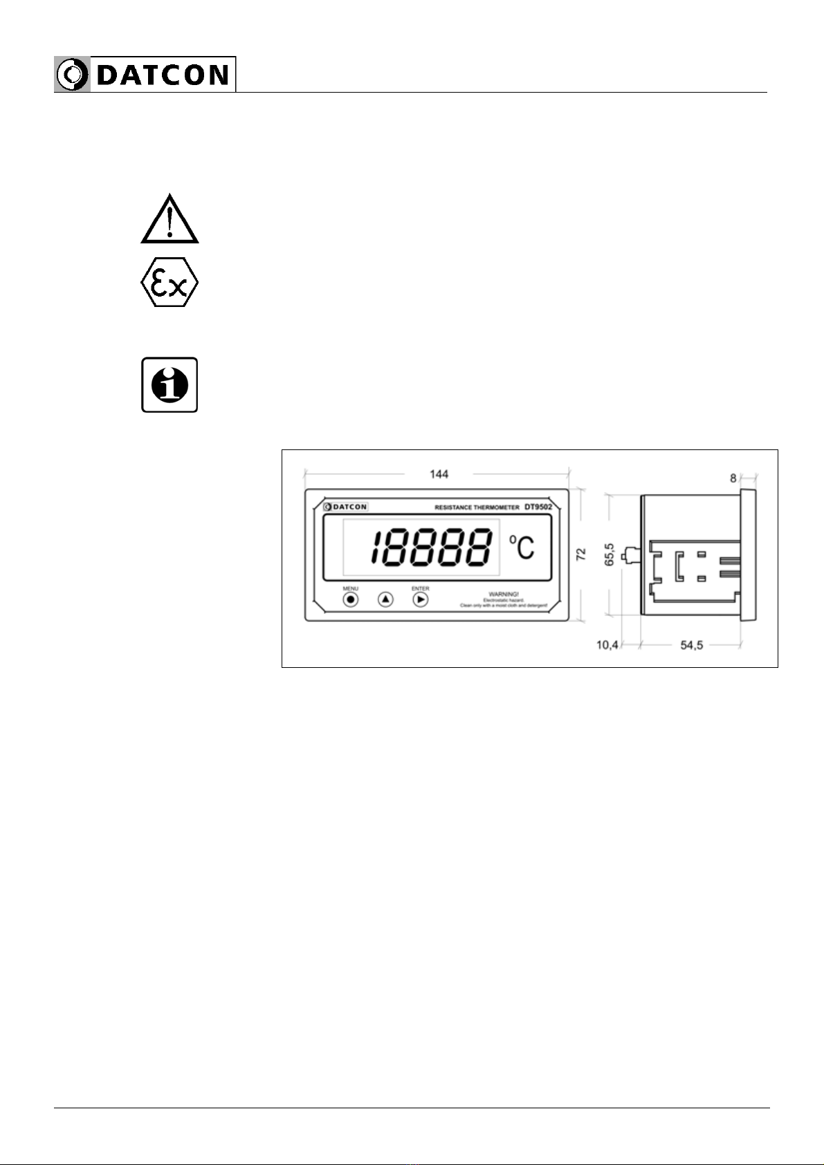
4.2. Main dimensions of the instrument.
DT9502
20171205-V3 11
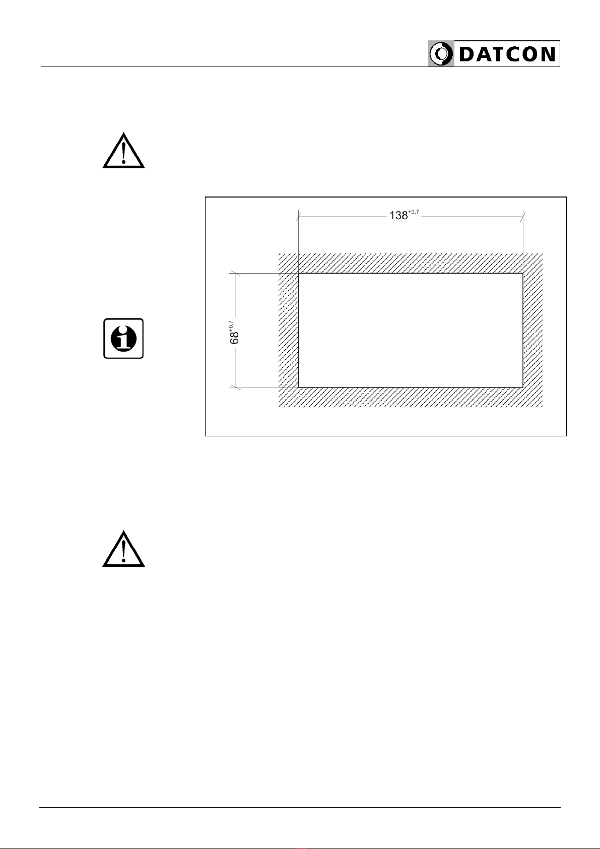
4.3. Mounting procedure
Preparatory steps
1. Cut-out the panel according to the figure shows below.
The cut-out needs special tools, it must be carried out by
trained specialist personnel.
Cut-out dimensions
2. Put on the enclosed seal onto the instrument case from
the rear side and fit it to the instrument front panel back
side.
3. Put the instrument into the prepared cut-out until it
possible and check the fitting of the seal between case and
mounting surface.

DT9502
12 20171205-V3
Mounting by the
mounting fixtures
4. Put on the two enclosed srew clamps onto the sides of
the instrument case (Figure step 1).
Fix the instrument by turning the srews in clockwise
direction (Figure step 2).
Pay attention not to let pointed, sharp metal parts cause
accidents.

DT9502
20171205-V3 13
5. Connecting
5.1. Connecting into the current loop
In hazardous areas you should take note of the appropriate
regulations, conformity and type approval certificates of the
DT9502 and other instruments are connecting in the current
loop (e.g. power supply, transmitter, etc.).
The connection must be carried out by trained and
authorised personnel only!
Select connection cable
A four-wire, twisted pair, shielded cable should be used for
connecting the measuring probe Pt100 to the apparatus. It
is also possible to use three-wire cables, but the
measurement accuracy will deteriorate due to the
asymmetry of the resistances of wires, and due to the
incertainty of contact resistances.
For connecting the loop-feeding, a two-wire, twisted pair,
shielded cable must be used.
For connecting the limit-value outputs, two-wire, twisted pair
cable with 500 V insulation may be used.

DT9502
14 20171205-V3
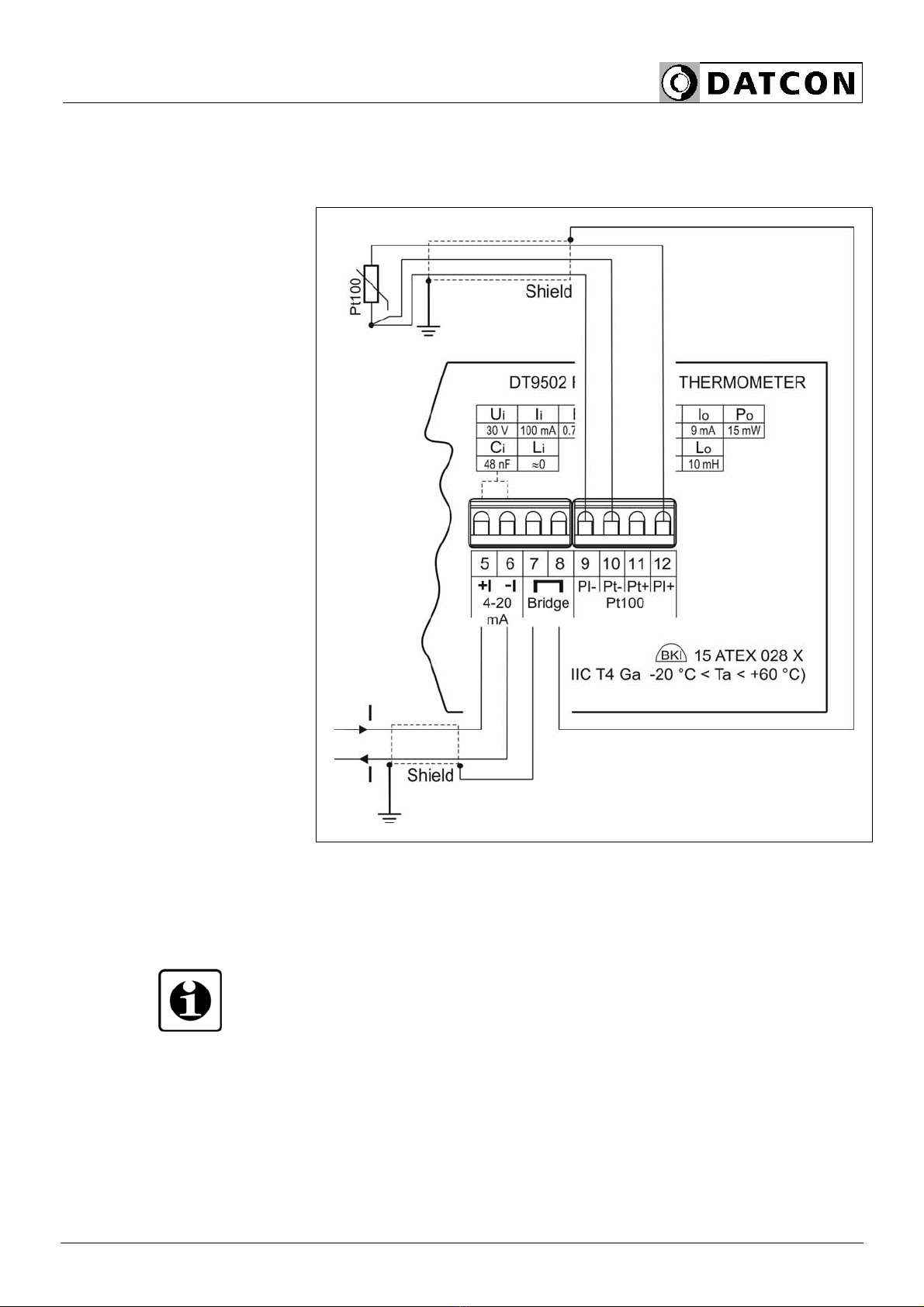
Connection
4-wire mode •The shieldings of the cables connected to Pt100 and to
the current loop must be connected with each other.
(see also “Application
example”)
Be careful the polarity of the cables.
The most accurate measurement can be achieved by the 4-
wire operating mode, as the cable resistances and their
possible asymmetry will not cause measuring errors.
In order to ensure accurate measurement its usage is
absolutely recommended.
DT9502
20171205-V3 15
Connection
3-wire mode •The shieldings of the cables connected to Pt100 and to
the current loop must be connected with each other.
(see also “Application
example”)
Be careful the polarity of the cables.
The 3-wire operating mode results in less accurate
measurement than the 4-wire operating mode, as the
different resistances of the cable wires, their asymmetry,
and the various temporary resistance values of contacts
cause additional measurement errors. The use of this mode
is recommended only for those cases that are satisfied by
less accuracy.
In all other cases it is practicable to use the 4-wire operating
mode (according to the connection depicted in the previous
page).

DT9502
16 20171205-V3
Wiring plan, connecting
the limit outputs
(see also “Application
example”)
Be careful the polarity of the cables.
Select connection cable
Select connection cable
for Ex applications
Take note the suitability of the connecting cable.
We recommend the use of screened twisted pair cable. The
wire cross-section should be 0.25-1.5 mm2.
Take note of the corresponding installation regulations for
Ex applications. In particular, make sure that no potential
equalisation currents flow over the cabre screen. In case of
grounding on both sides (for suppress the influence of high
frequency interference signals) this can be achived by use
of a capacitor (e.g. ceramic capacitor 1 nF, 1500 V) or
separate potential equalisation. The low frequency potential
equalisation currents are thus supressed, but the protective
effect against high frequency interference signals remains.
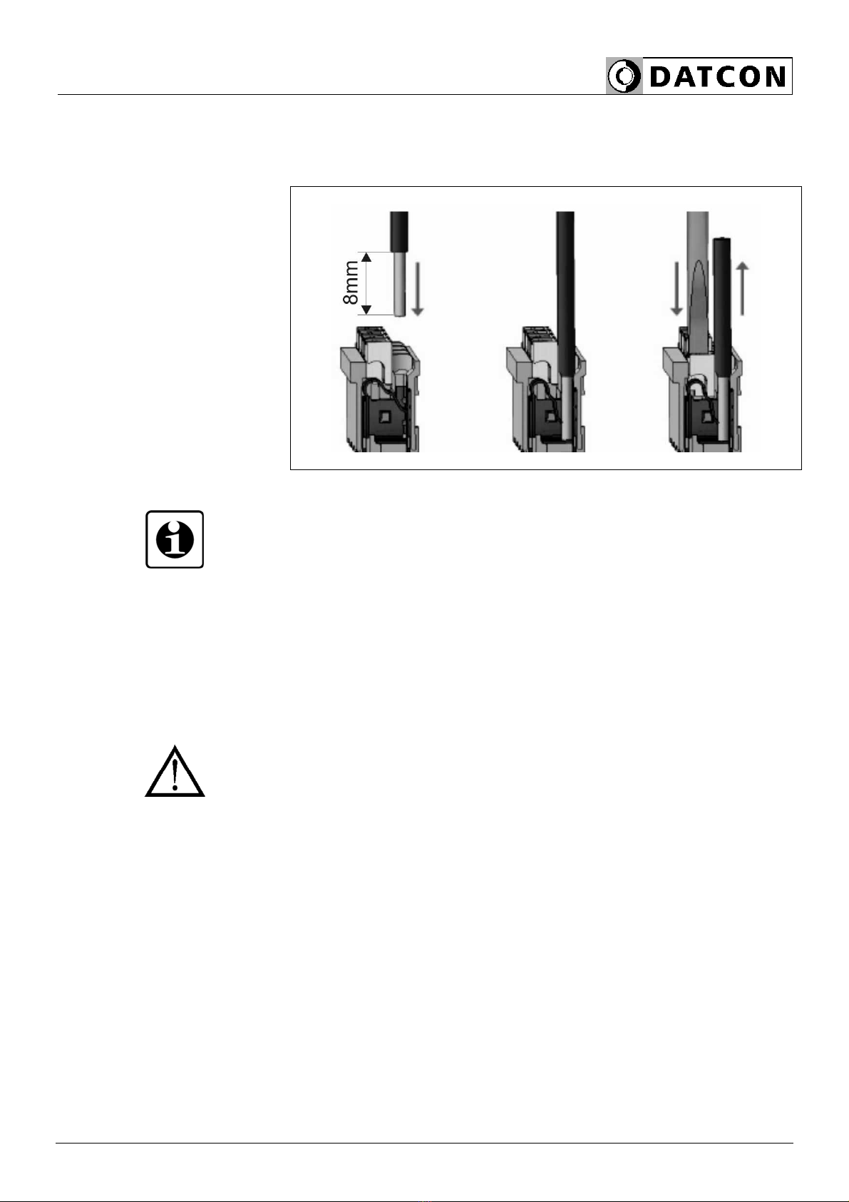
Preparing cables Remove approx. 30 mm of cable mantle, strip approx.
8 mm insulation.
DT9502
20171205-V3 17
The push-in direct connector assemblies used allow a fast
connection of the cables.
Their proper usage is shown by the following figure:
Connecting the cables
into the terminal
assemblies
1. Push the stripped cable-end until it possible into the
terminal assembly. In the case of flexible cable-ends, you
can facilitate opening the connection part by pushing down
the white button.
2. By pushing the wire in, the self-closing connection is
being established. Check it by pulling it outwards slightly.
(3. When you disassemble the cable, push down the white
button by a screwdriver, and pull the cable-end out.)
There is no need to use great force for pushing the cable in,
neither for removal. The button can be pushed down easily.
Please do not exercise forces higher than necessary, as it
may cause damages to the terminal assembly.

DT9502
18 20171205-V3
Finishing step Check if the cables are connected properly (have you
connected all the cables; have you connected them to the
right place; is the connection stable; do not the cable-ends
touch each other).
Checking the connection
After the connections have been made, put the
measurement loop (the measuring transformer) under
voltage, if possible.
If the connection is perfect, some numbers or a text appear
on the display.
If nothing appears on the display, most probably the
apparatus does not get supply power. With a voltage meter
instrument check if there is voltage between +I and -I
connection points. If the measurement shows that the
voltage value is higher than 12 V, then this error-possibility
can be excluded.
In the next step, you may suspect that the cables are
connected to the apparatus with reverse polarity (the two
wires of the cable are interchanged), or they are connected
not to the specified terminal-assembly points. Check if
everything has been done in accordance with chapter 5.1.
Connection to the measurement loop.
With this you have completed the connection of DT9502.

DT9502
20171205-V3 19
6. The display and the operating devices
6.1. The first start-up
The display
The dispay is shown by the arrow (1).
After the apparatus has been installed to its place, the
probe Pt100 has been connected in accordance with the
specified mode, and the connection to the measurement
loop has been established, then the display of the
apparatus shows the measured temperature values with an
accuracy of the decimal of the degree. Accordingly, if the
temperature is 24.2 degrees centigrade, the following is
visible on the display:.
If it is 123.7 °C, then:.
As the factory default setting of the apparatus is 4 wires for
Pt100 connection, the displayed value will be accurate in
that case only if actually 4 wires are used for the
connection. If a 3-wire physical connection is used, the
setting of the apparatus must also be changed to this mode,
in order to ensure accurate measurement (Chapter 7.2,
menu 04)
In the case of error
messages
If something else appears on the display instead of the
measured temperature values (a message written by
blinking letters), then it is an error message of the apparatus
DT9502.
In order to identify the fault, go to the Appendix at the end of
this Operating Instructions, and see chapter 10.3 Error
messages or 10.4. Messages of critical errors.

DT9502
20 20171205-V3
6.2. Characters and mnemonics appearing on the
display
DT9502 has a 7-segment type display. It means that
maximum 7 bars are used to form each characters. The
numbers can be read easily, some of the letters, marks
however, looks unusual:
= A, = B, = C, = D, = E, = F, = G,
= H,= I, = J, = K, = L, = M, = N,
= O, = P, = Q, = R, = S, = T, = U,
= V, = W, = X, = Y, = Z
All mnemonics (code words) presented on the display
comes from English expressions in abbreviated form.
The following part gives a list of the possible mnemonics
and their meaning. The left-side column shows the
characters appearing on the display. The right-side column
gives first the meaning, then the full English word in
brackets and, after the hyphen, and explanation may be
given.
Login text
DT - Datcon instrument
9502 - Type of the instrument
The device is preparing for the measurement
Error messages
A/D overflow (Error: AD Overflow)
Measurement missing (Error: MeaSuremenT)
Underflow (Error: Underflow)
Overflow (Error: Overflow)
Missing Minimum-Maximum (Error: Missing Minimum-
Maximum)
Measurement (Error: MeaSuremenT)
Table of contents
Other Datcon Measuring Instrument manuals

Datcon
Datcon DT9000 User manual

Datcon
Datcon DT4240 Series User manual

Datcon
Datcon DT4120 Series User manual

Datcon
Datcon DT9002 User manual

Datcon
Datcon DT920 User manual

Datcon
Datcon DT4200 User manual

Datcon
Datcon DT4260 Series User manual

Datcon
Datcon DT9500 User manual

Datcon
Datcon DT4227 UI User manual

Datcon
Datcon PQRM5300 33 U I Series User manual


