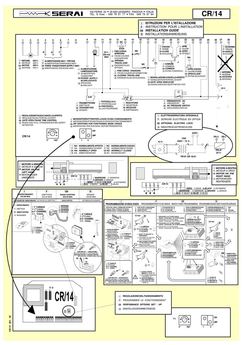
Serai CR/41 User manual

INSTALLATION OF THE CONTROL PANEL CR/41
Place the device near the gate, in order to have the minimum lenght of the cables for connection with the system.
We suggest to place the control panel under a cover or in a place with two lateral walls, to protect it against the
weather conditions. Moreover fix it at 1,5m height so to be far from children.
WHERE PLACING THE CONTROL PANEL
The control panel is supplied from factory with the opening towards the left side. It is possible to change the opening,
please follow the below instructions:
Insert a screwdriver in the hole for the hinges-fixing in the
back side (as shown in the picture) and pull the cover,
pressing the fixing “tooth” (picture 1)
Fig.1
Insert a screwdriver in the hole for the hinge-fixing which is in
the front side of the cover and pull the hinge pressing the
“tooth” (picture 2)
Fig.2
DAL 1965
Install the hinges on the right side of the back cover,
insert them with the fixing “tooth” towards the indoor
part of the cover until the click (picture 3)
Fig.3
COVER OPENING: TOWARDS THE RIGHT SIDE
Pag. 1/10
CR/41 I E 01 10 02072007
ATTENTION: This operation has to be made before the
fixing on the wall.
!
E R A IS
GATE OPENERS DEPARTMENT

DAL 1965
CABLES’ PASSAGE
For the entry of the cables, in the lower part of the cover, holes are already prepared for the glands PG11 and PG
13,5
Cable passage
!ATTENTION: close tightly all the entries to avoid insects
passage and so possible damages.
Pag. 2/10
CR/41 E
WALL FIXING OF THE CONTROL PANEL
We suggest to install the device near the gate, in order
to have the minimum lenght of the cables for the
connection with the whole system.
The control panel has to be fixed with the holes for the
passing of the cables downwards
NO NO YES
Ø 6 ÷ 8 mm
aaaaaa
aaaaaa
aaaaaa
aaaaaa
aaaaaa
aaaaaa
OPENING AND CLOSING OF THE BOX
Advices for generical spaces connections, according to Italian Law ( CEI 64-8 ).
1.Predispose at the bottom of the system an omnipolar disconnecting switch with
distance between contacts of 3 mm or more. On alternative choice it is possible to use
a magnetothermic switch of 10A.
2.Make any kind of connections with no power supply on the system, or with the
disconnecting switch on “ open “ position ( symbol “0” ). Particularly, the control panel
must never be supplied during the wiring, nor when inserting the expansion cards.
3.During the installation use following wires.
- For control panel, motors and electric lock power-supply: 1,5mm² for max. lenghts of
19m, section 2.5mm for lenghts up to 31m
- For the flashing light: section 0.75mm² for max. lenght of 3m, section 1.5mm² for
lenght up to 19m
- For low voltage lines and current, such as photocells, command buttons,
electromechanical key, sensitive edge and other safety devices: section 0.5mm² for
max. lenght of 50m, section 0.75mm² for lenght up to 100m.
2
When you open the box, control that the hinges exit from their
location in order that the cover can remain open during the
electrical connections.
Close carefully the cover, the hinges have to be correctly
inserted.
Close the cover with the screws.

DAL 1965
DAL 1965
Pag. 3/10
CR/41 E
F1
F2
ON
SW1 SW2
345 6 78
POWER
+
-
ON
PED START STOP FOTO FOTO AP FINE CH FINE AP
DL9 DL8
DL10
1 2 910 11121314 15161718 19 20 21 22
272526
2324
28 29
OPEN
CLOSE
COMMON
230V~ ±10%
50/60Hz
FN
FLASHING-LIGHT
230V~
COURTESY LIGHT
230V~
OPEN
CLOSE
COMMON
M2M1
PED
NC
NC
CLOSING
PHOTOCELLS
RECEIVERTRANSMITTER
OPENING
PHOTOCELLS
RECEIVERTRANSMITTER
NC
NC
NO
NC
NO
PEDESTRIAN
START
STOP
ELECTRIC-LOCK
12 Vac 15VA max
EX. SERAI M/83/1
24 Vac
CONNECTION DIAGRAM
CLAMPS CONNECTIONS DESCRIPTION
21 - 22 POWER SUPPLY Entry for electronic card power supply 230Vac 10% 50/60 Hz
±
11 - 12 FLASHING LIGHT Output for flash-light power-supply (230Vac - ), for lamps without
the inside electronic - for ex. SERAI RZ/20F -
max 50W
12 - 13 COURTESY LAMP Output for courtesy lamp (230Vac- ): switched-on for 90 sec. after the STOPmax 100W
14 - 15 - 16 MOTOR M1 Output for motor M1 power-supply (14=common, 15=opening, 16=closing) for
single wing or pedestrian opening (the wing to which is connected the electric lock)
26 - 27 PHOTOCELL
POWER-SUPPLY Output for power supply 24Vac ( ) for accessories such as photocellsmax 500mA
6
OPENING
PHOTOCELL /
SENSITIVE EDGE
8 - 9 NOT USED Make a short-circuit on the common with jumpers.
5CLOSING
PHOTOCELL
2
4
PEDESTRIAN
OPENING
Entry for the pedestrian opening (contact NO). With DIP1 SW1 OFF it opens
only the wing connected to M1. With DIP1 SW1 ON it opens the wing for 7 sec.
STOP
Entry for the STOP (contact NC): when pressed the working of the motors is
interrupted, if pressed during the pause time when the gate is open, the
automatic reclosure is canceled.
3START
OPENING
Entry for the start drive (contact NO) opening and closing with step-by-step
function.
With DIP4 SW2 OFF: entry for photocell activated in opening and
closing phase (contact NC). If obscured during opening the gate
stops until the photocells remains obscured. During closing the gate
stops and reverses the movement.
With DIP4 Sw2 ON: entry for sensitive edge (contact NC).
Entry for photocells activated only in closing phase (contact NC). If
obscured during the closing phase it stops the gate and reverses
1 - 7 - 10 COMMON
ENTRIES
Common clamps of the entries
17 - 18 - 19 MOTOR M2 Output for motor M2 power-supply (17=common, 18=opening, 19=closing)
for motor with delayed opening (gate with 2 wings)
25 - 26 ELECTRIC LOCK Output for electric-lock 12 Vac 15 VA max
23 - 24
ANTENNA
INTEGRATED
RECEIVER
Entry for the connection of the antenna to the integrated receiver
(23= 24= )SHIELD ANTENNA
28 - 29
OPEN GATE
SIGNAL
Output 24Vdc (28 , 29 ) for the connection of the open-
gate signal.
+ -
ATTENTION: to connect lamps with absorption more than
50mA, it is necessary to use an additional outside relay.
max 50mA
DELAY
IN OPENING
SET BREAK WORK
ABC
Com
+24
20 NOT USED
spia
12Vac
RX
TURN OFF POWER SUPPLY
BEFORE WIRING-UP
ADDITIONAL
RELAY
24Vdc - max 50mA
2928
LIGHT
POWER SUPPLY
LIGHT
FUSES:
F1 = 2A 250V~
-
F2 = 5A 250V~
-POWER SUPPLY
ACCESSORIES 24V-
230V-
SW1= Dip-switches to set the control panel
A= Push-button to enter into programming
(SET)
B= Push-button to program the times
(BREAK)
C= Push-button to program the times
(WORK)
POWER= Trimmer to adjust the motor force
SW2= Dip-switches to set the control panel LIGHT 24Vdc
max 50mA

CR/41 E
DAL 1965
Pag. 4/10
ELECTRICAL CONNECTION OF THE MOTOR
Connect the motors to the control panel using cables with 1,5mm
CABLE LIGHT BLUE : Common
CABLE BROWN : Open/Close - Capacitor
CABLE BLACK: Open/Close - Capacitor
CABLE YELLOW-GREEN : Ground
The following indications have to be respected (CEI 64-8):
- Connect the cable yellow-green to a good ground system
- Install at the bottom of the system, an omnipolar switch with at least
3mm as opening distance between the contacts.
² section.
Respect the colour of the cables as follows:
YELLOW GREEN =
GROUND CONNECTION
LIGHT BLUE =
COMMON
BLACK=
OPEN/CLOSE
BROWN=
OPEN/CLOSE
SI 12,5 µF
450V
NO
!
Fig 13
ATTENTION: the high
temperatures cause
different expansions
in all materials,
including the material
of our products. For
this reason we
recommend to control
the motor force
adjusting each winter
and summer in the
beginnig of each
season.
differencies in the
summer and winter
GROUND CONNECTION BETWEEN MOTOR AND THE HOUSE
MOTOR FORCE ADJUSTMENT
The setting of the motor force is made by changing the voltage through the trimmer “Power” in the control panel
CR/41.
The installation has to be carried out in the full respect of the current Laws concerning the gate automaton.
Please consider that the responisibility of the system and its working respecting the “standards” is of the
installer.
F1
F2
ON
SW1 SW2
345 6 78
POWER
+
-
ON
PED START STOP FOTO FOTO AP FINE CH FINE AP
DL9 DL8
DL10
1 2 910 11121314 1516171819 20 21 22
272526
2324
SET BREAK WORK
A B C
Com
+24
spia
RX
CABLES
YELLOW-GREEN
OF MOTORS
CONNECTION
CLAMP
CABLE
POWER-SUPPLY
230 V~
CABLE
MOTOR 2
CABLE
MOTOR 1
CABLE
YELLOW-GREEN
HOUSE SYSTEM

DAL 1965
Pag. 5/10
CR/41 E
DIP-SWITCH SET-UP
DIP-SWITCH
SET-UP
DESCRIPTION
FUNCTION
- One-wing gate: it drives only the oputput indicated as M1
- Double-wing gate: it drives the outputs M1 and M2 (M2 is the wing
which has the delay in opening)
KIND OF
GATE
1 2 3 4 1 2 3 4
1 2 3 4 1 2 3 4
SLOW-DOWN
SET-UP
1 2 3 4 1 2 3 4
1 2 3 4 1 2 3 4
- Slow down speed: HIGH
- Slow down speed: LOW
- Final push activated: at the end of the closing, the motors receive
full power for 2 sec. in order to hook better the electric lock.
- Final push not activated
FINAL PUSH
IN CLOSING
- Kick-back activated: the electric lock is activated for a short closing
phase against the stop blocks and it is released after the start of
M1.
- Kick-back not activated: the electric lock is activated when M1
start and released immediately after the movement.
1 2 3 4 1 2 3 4
1 2 3 4 1 2 3 4
1 2 3 4 1 2 3 4
1 2 3 4 1 2 3 4
ELECTRIC LOCK
KICK BACK
1 2 3 4 1 2 3 4
1 2 3 4 1 2 3 4
STARTING
ACCELERATION
- Starting acceleration activated: when the motors start, they
receive full power-supply for 2 sec.
- Starting acceleration not activated: when the motors start, they
receive the power-supply as the voltage set with the trimmer.
1 2 3 4 1 2 3 4
1 2 3 4 1 2 3 4
SLOW-DOWN
SET-UP
- Slow-down not activated
- Slow-down activated
!
ATTENTION:
The set-up of the dip-switches has to be made with no power-supply to the control panel. When the
control panel is switched on, the set-up is confirmed and activated.
We suggest, after the dip-switch set-up, to program the working time (see Control panel
programming).
!
ATTENTION: During the slow-down the force decreases and so the speed depends from the
characteristics of the motor and the gate.
A SLOW-DOWN SPEED TOO MUCH LOW MAY PREVENT THE REGULAR WORKING
OF THE WING.
SW1 SW2
!
ATTENTION: When the motors MT/30/2 and MT/38/1 arrive against the stop blocks, there are
some vibrations - not dangerous - which may cause noise.
To avoid this noise the slow-down must be deactivated (dip2 SW2 ON).

DAL 1965
Pag. 6/10
CR/41 E
- A start impulse during the opening stops the gate.
- Another impulse closes the gate.
STE-BY-STEP
FUNCTION
NOT ACTIVATED
DURING
OPENING
- A start impulse during the closig stops the gate for 2 sec. and
opens it automatically.
- A start impulse during the opening is not considered. A start
impulse during the pause with the gate opened closes the gate.
DURING
CLOSING
2 s
start start
start
start
DURING
OPENING
DURING
CLOSING
THE SENDING OF
AN IMPULSE
DURING THE
GATE
MOVEMENT
DIP-SWITCH
SET-UP
DESCRIPTION
FUNCTION
1 2 3 4 1 2 3 4
1 2 3 4 1 2 3 4
- A start impulse during closing stops the gate for 2 sec. and opens
it automatically.
2 s
start
ENTRY
FOR
OPENING
PHOTOCELL
OR
SENSITIVE EDGE
1 2 3 4 1 2 3 4
1 2 3 4 1 2 3 4
- Function “sentive edge” activated: the entry to clamp 6 reverses the
motion of 10cm during opening or closing.
- Function “opening photocell” activated: the entry to clamp 6 stops
the motion during the opening, while reverses the motion during the
closing.
THE MEANING OF EACH LED
LED
FINE CH
FINE AP
FOTO AP
FOTO
STOP
PED
START
ON OFF
FUNCTION
Inside photocell
External photocell
STOP button
PEDESTRIAN button
Open/Close button
Opening Photocell free
Closing Photocell free
STOP button not pressed
Pedestrian button pressed
Open/Close button pressed
Correct connection of
8-10 clamps The Jumper on 8-10 clamps is missing
Fotocellula Apertura oscurata
(presenza di un ostacolo)
Fotocellula Chiusura oscurata
(presenza di un ostacolo)
STOP button pressed
Pedestrian button not pressed
Open/Close button not pressed
DL10 Programming It is used during the programming
DL8 Motor M2 Different brightness according to
the voltage to the motor M2
No power-supply to motor M2
DL9 Motor M1 Different brightness according to
the voltage to the motor M1
No power-supply to motor M1
Correct connection of 9-10
clamps The Jumper on 9-10 clamps is missing
STEP-BY-STEP
FUNCTION
ACTIVATED
SW 2SW 1

DAL 1965
Pag. 7/10
CR/41 E
CONTROL PANEL PROGRAMMING
It is important to follow carefully step by step the programming, if mistakes happen during this phase it is necessary
to make a new programming from the beginning.
To quit the programming switch on and off the control panel.
Before proceeding with the programming it is necessary to control that all electrical and safety devices are
connected (push-button, photocells, flashing light, etc...)
Check their correct functionning and if necessary:
All LED for the NC entries must be (stop, photocells etc...)
All LED for the entries NO must be (start, pedestrian)
ON
OFF
A jumper must be placed on the normally closed (NC) entries not usedATTENTION:
PROGRAMMING OF THE WORKING TIME AND THE SLOW-DOWN FOR A DOUBLE-WING GATE (DIP1 SW1
OFF)
Control panel ON, gate closed. Press one time the button A (SET) to enter into programming. LED DL10 starts
flashing. The programming phase begins.
Press one time the push-button B (BREAK) to make motor M2 starting. The time that you wait from the beginning
of the opening of M1 and the pressing of B (BREAK) is the delay of opening of the second wing. This time is max
15 sec. If you do not press any button after 15 sec. The motor M2 starts automatically the opening.
While the two wings are opening, adjust the power of the motor turning the trimmer POWER.
ATTENTION: - if the trimmer POWER is set two “low”, the gate may not open. We suggest to make this
setting starting with the trimmer turned to the MAXIMUM and decreasing the power while the wing is
opening.
- The high differences of temperature between summer and winter cause different
expansions in all materials, including the material of our products. For this
reason we recommend to control the motor force adjusting each winter and
summer in the beginnig of each season.
ATTENTION: - If you want to change some of the above adjustment it is necessary to repeat
the programming from the beginning.
- During programming the slow-down is set only in the closing phase but
During the standard working it is used also in the opening phase.
Press one time push-button C (WORK): the motor M1 starts the opening (M2 remains still).
When the wing of motor M1 arrives against the stop blocks wait for 3-4 seconds and after press one time button
C (WORK). Motor M1 switches OFF.
When the wing of motor M2 arrives against the stop blocks wait for 3-4 seconds and after press one time button
C (WORK). Motor M2 switches OFF.
When the two wings are completely open and the motors are not supplied, press one time button B (BREAK) to
start the closing phase of motor M2 (M1 remains still).
Press one time the push-button C (WORK) to make also motor M1 starting. The time that you wait from the
beginning of the closing of M2 and the pressing of C (WORK) is the delay of closing of the wing. This time is
max 15 sec. If you do not press any button after 15 sec. The motor M1 starts automatically the closing.
During the closing, press B (BREAK) when you want that the motor M2 starts the slow-down (we suggest at
least from the stop blocks). Motor M2 starts the slow-down.50cm ATTENTION: DO NOT consider this point if
the slow-down is not activated (DIP2 SW2 ON)
During the closing, press C (WORK) when you want that the motor M1 starts the slow-down (we suggest at
least from the stop blocks). Motor M1 starts the slow-down.50cm ATTENTION: DO NOT consider this point if
the slow-down is not activated (DIP2 SW2 ON)
When the wing of motor M2 arrives against the stop blocks wait for 3-4 seconds and after press one time button
B (BREAK) Motor M2 switches OFF.
When the wing of motor M1 arrives against the stop blocks wait for 3-4 seconds and after press one time button
C (WORK). Motor M1 switches OFF and control panel quit automatically from programming. It is ready for
functionning.

DAL 1965
Pag. 8/10
CR/41 E
Control panel ON, gate closed. Press one time the button A (SET) to enter into programming. LED DL10 starts
flashing. The programming phase begins.
While the wing is opening, adjust the power of the motor turning the trimmer POWER.
ATTENTION: - if the trimmer POWER is set two “low”, the gate may not open. We suggest to
make this setting starting with the trimmer turned to the MAXIMUM and
decreasing the power while the wing is opening.
- The high differences of temperature between summer and winter cause different
expansions in all materials, including the material of our products. For this
reason we recommend to control the motor force adjusting each winter and
summer in the beginnig of each season.
ATTENTION: - If you want to change some of the above adjustment it is necessary to repeat
the programming from the beginning.
- During programming the slow-down is set only in the closing phase but
during the standard working it is used also in the opening phase.
Press one time push-button C (WORK): the motor M1 starts the opening.
When the wing of motor M1 arrives against the stop blocks wait for 3-4 seconds and after press one time button
C (WORK). Motor M1 switches OFF.
When the wing is completely open and the motor is not supplied, press one time button C (WORK) to start the
closing phase.
During the closing, press C (WORK) when you want that the motor M1 starts the slow-down (we suggest at
least from the stop blocks). Motor M1 starts the slow-down.50cm ATTENTION: DO NOT consider this point if
the slow-down is not activated (DIP2 SW2 ON)
When the wing of motor M1 arrives against the stop blocks wait for 3-4 seconds and after press one time button
C (WORK). Motor M1 switches OFF and control panel quit automatically from programming. It is ready for
functioning.
PROGRAMMING OF THE PAUSE TIME WITH OPEN GATE (AUTOMATIC RECLOSURE)
Control panel ON, gate closed. Press one time the button A (SET) to enter into programming. LED DL10
starts flashing. The programming phase begins.
Press one time B (BREAK) - flashing light ON - the control panel starts to count the time for the pause
when the gate is open, one flashing = 1 second.
Press B (BREAK) when you want to fix the time choosen for the pause, the control panel memorize the
time from the first and the second pressing of B (BREAK).
It quit automatically from programming.
If you do not press any button, after the maximum time of 120 sec. the control panel quit the programming
memorising 120 sec.
ACTIVATE THE AUTOMATIC RECLOSURE (MAX 120sec.)
Press and keep pressed B (BREAK) until LED Dl10 switches OFF.
Control panel quit automatically from programming.
The automatic reclosure is deactivated.
DEACTIVATE THE AUTOMATIC RECLOSURE
Control panel ON, gate closed. Press one time the button A (SET) to enter into programming. LED DL10
starts flashing. The programming phase begins.
PROGRAMMING OF THE WORKING TIME AND THE SLOW-DOWN FOR GATE WITH ONLY ONE WING (DIP1 SW1 ON)

LEARNING OF TRANSMITTER CODE
The control panel has an incorporated two-channel receiver at 433,92 Mhz which allows to remotely drive the gate
through transmitters at dip-switches - OG/02 and OG/04 - and also self-learning transmitters OG/62, OG/64,
OG/52, OG/54, OG/82/1 and OG/84. The first channel of the receiver works like a start, while the second channel
works like “pedestrian” start.
ERASING OF THE STORED CODES
Keep pressed the button A (SET) for about 10sec. Until the LED DL10 switches off.
!ATTENTION: - before using a transmitter, it is compulsory to program it
- the max number of codes is 32 for the START function and 32 for the
PEDESTRIAN function (different combination are not possible: for ex. 40 start + 24
pedestrian NOT POSSIBLE).
Some examples of the possible combinations:
32 self-learning transmitters- example A: OG/62, OG/64, OG/28, OG/48, OG/52,
OG/54, OG/82/1 or OG/84 as (for ex. the left push-button)+
OG/62, OG/64, OG/28, OG/48, OG/52, OG/54,
OG/82/1 or OG/84 as (for ex. the right push-button)
- example B: OG/62, OG/64, OG/28, OG/48, OG/52,
OG/54, OG/82/1 or OG/84 as (for ex. the left push-button) +
OG/02, OG/04 as (it is not necessary to program
the other OG/02 or OG/04 since it is enough to set the dip-switches in the
same position) + OG/62, OG/64, OG/28,
OG/48, OG/52, OG/54, OG/82/1 or OG/84 as (for ex. the right
push-button) + OG/02, OG/04 as (it
is not necessary to program the other OG/02 or OG/04 since it is enough
to set the dip-switches in the same position)
start 32 self-
learning transmitters
pedestrian
31 self-learning transmitters
start 1 dip-
switch transmitter start
31 self-learning transmitters
pedestrian
1 dip-switch transmitter pedestrian
!
DAL 1965
Page 9/10
LEARNING OF THE START CODE
- Control panel ON, gate closed. the button A (SET) to enter into programming. LED DL10 starts
flashing. The programming phase begins.
- Press the button in the transmitter (for ex. the left button) and keep it pressed until LED DL10 switches OFF. The
control panel has memorised the code and it quit automatically from programming.
- Repeat the same step if you need to program other transmitters.
Press one time
LEARNING OF THE PEDESTRIAN CODE
- Control panel ON, gate closed. the button A (SET) to enter into programming. LED DL10 starts
flashing. The programming phase begins.
- the button A press the button in the transmitter (for ex. the right button) and keep them pressed
until LED DL10 switches OFF. The control panel has memorised the code and it quit automatically from
programming.
- Repeat the same step if you need to program other transmitters.
Press one time
Keeping pressed
12 3 4 56 7 8910
12 3 4 5 6 7 8 9 10
!
CHANGE THE FACTORY SET-UP
TO AVOID NOT WANTED DRIVES
DIP-SWITCH SET-UP ONLY FOR TRANSMITTERS OG/02 AND OG/04
Only in the event that the dip-switches transmitters OG/02 or OG/04 are used, it is necessary to change the dip-
switch set-up before the programming, in order to change the factory set-up.
ATTENTION:before proceeding with the programming or the erasing of the transmitters it is
necessary to disconnect temporarily the antenna to avoid that the receiver during these phases
acquires other signals which may cause the uncorrect functionning of the system.
Connect the antenna as soon as finished.
CR/41 E

CR/41 E
CONTROL PANEL TECHNICAL DATA
Power-supply: 230Vac ±10% 50/60Hz
Motor power-supply: 2 motors single phase 230Vac, 200W+200W
Accessories power-supply: 24Vac, 500mA
Flashing-Light power-supply: 230Vac, max 50W
“Courtesy lamp” power-supply: 230Vac, max 100W
Electric lock power-supply: 12Vac 15VA
Adjustment of the motor working time: from 0 to 120sec.
Adjustment of the pause time: from 4 to 120sec.
Adjustment of the 2nd wing delay in opening + closing: from 0 to 15sec.
Working temperature: -20°C ÷ +70°C
Protection degree: IP54
Dimensions and weight: 270x212x118mm, 1,7Kg
INCREASING THE NUMBER OF TRANSMITTERS
If it is necessary to store more than 32 transmitters on the integrated receiver, you have to replace the existing receiver
with the SOG/4A (to have 40 transmitters) and eventually the expansion card SOG/2A (to reach 794 transmitters). After
this replacement it is necessary to program again all the transmitters, see the SOG/4Ainstructions.
OUTPUT
2nd CHANNEL:
AUXILIARY
COMMAND
ANTENNA
NC
C
NA
Output channel 2 (contact
relay)
Max vcoltage =
Max current =
Install an additional relay
if necessary, according to the
specific application
24Vac/dc
1A
ELECTRIC LOCK
LAMPS
OTHER AUTOMATIC
SYSTEMS
ALTRO
F1
F2
ON
SW1 SW2
345 6 78
SOG/4
POWER
+
-
ON
PED START STOP FOTO FOTO AP FINE CH FINE AP
DL9 DL8
DL10
1 2 910 11121314 15161718 19 20 21 22
272526
2324
28 29
SET BREAK WORK
A B C
Com
+24
spia
RX
TAKE OUT THE
INTEGRATED
RECEIVER
INSERT THE
RECEIVER SOG/4A
OUTPUT 1st CHANNEL:
START COMMAND
OF THE
CONTROL PANEL
PEDESTRIAN
COMMAND
ON CR/41
-CLAMPS 1-2-
TURN-OFF POWER SUPPLY
BEFORE ANY WIRING UP
VIA ENRICO FERMI, 22
35020 LEGNARO - PADOVA
I T A L I A
TEL +39 049 79 08 58
FAX +39 049 883 05 29
international
international
E-MAIL [email protected]
WEB www.serai.com
E L E T T R O N I C A P A D O V A
I
D A L 1 9 6 5
Table of contents
Other Serai Control Panel manuals
Popular Control Panel manuals by other brands
GAS
GAS Gasmaster Installation, operation and maintenance manual

Halma
Halma SENSITRON MULTISCAN++ PK-32 manual
XFP
XFP XFP501E/X Engineering manual

Siemens
Siemens SINUMERIK MCP-S Series Equipment manual
LOVATO ELECTRIC
LOVATO ELECTRIC FFLRA200 installation manual
INSBUD
INSBUD IB-TRON 4000 SOL instruction manual
