Sercel GRC Fortress SPS-1500 User manual


Doc. No. 006-0202-00 Rev AH 2
NOTICE
This manual is intended for private information only, with the understanding that any
other use of the subject matter, in whole or in part, by reference or otherwise, shall be
only with the prior knowledge and approval of Sercel-GRC Corp., and with the further
understanding that this manual is for informational purposes only and that suggestions
and recommendations contained herein shall not be understood or construed as a
guarantee or warranty of any method, product or device.
Federal copyright law protects the publication. No part of this publication may be copied
or distributed, transmitted, transcribed, stored in a retrieval system, or translated into
any human or computer language, in any form or by any means, electronic, magnetic,
manual or otherwise, or disclosed to third parties without the express written permission
of Sercel-GRC Corp.
Any questions concerning the content of this manual, equipment operation, field
maintenance, maintenance assistance and operation or maintenance training courses
should be directed to:
MODEL:
SPS-1500/SPS-1501 Operations Manual
V4.2 Update
Copyright © 2015 by Sercel-GRC Corp.
All rights reserved worldwide.
Document Number: 006-0202-00 Rev AH
Sercel-GRC Corp.
13914 E. Admiral Place, Ste. B
Tulsa, OK 74116-2107
Telephone: (1) 918-834-9600 / Fax: (1) 918-838-8846

Doc. No. 006-0202-00 Rev AH 3
TABLE OF CONTENTS
1.0 SPS-1500/SPS-1501 Board Overview......................................................................4
1.1 SPS-1500 Specifications.......................................................................................4
1.2 SPS-1501 Specifications.......................................................................................4
1.3 Default/Factory Settings SPS-1500 & SPS-1501..................................................4
1.4 DC Power Supply (Optional).................................................................................4
2.0 SPS-1500/SPS-1501 Connections............................................................................5
3.0 SPS-1500/SPS-1501 LCD ........................................................................................6
3.1 Status & Diagnostic Screens.................................................................................6
3.2 Status & Error Message........................................................................................7
4.0 SPS-1500/SPS-1501 DataWorks Software Configuration.........................................8
4.1 DataWorks 1.04 Configuration Menu....................................................................8
4.2 Modbus Communication Map Settings................................................................11
4.3 Modbus Slave ID & Baud Rate Settings .............................................................13
4.4 SPS Configuration Settings.................................................................................14
4.5 SPS Manual Operation .......................................................................................14
4.6 Firmware Update ................................................................................................15
5.0 ESP ‘E’ Series Sensor Configuration ......................................................................16
6.0 High Speed Operation.............................................................................................19
Appendix.......................................................................................................................21
1 SPS-1500/SPS-1501 Troubleshooting.......................................................................21
2 SPS-1500/SPS-1501 Modbus Map............................................................................23
3 CE Compliance Certifications.....................................................................................25
4 SPS-1500 Synchronization and Startup.....................................................................26

Doc. No. 006-0202-00 Rev AH 4
1.0 SPS-1500/SPS-1501 Board Overview
1.1 SPS-1500 Specifications
GRC P/N: 90B3125
Certifications: CE Compliance Tested (see Appendix)
Dimensions: 3.47”W, 3.68”L, 2.30”H
Voltage Input: 12 to 28 VDC, 0.5 Amp Max
Polling Interface: RS-485/RS-422 Isolated Modbus
PC Interface: Isolated USB COM Port for Modbus/Firmware Update
Supported Baud Rates: 1200, 2400, 4800, 9600, and 19200 bps
Display: 16x2 Backlit LCD
Gauge Power Out: 40 to 80 VDC Out (~80mA Current Limited)
Gauge Power Fuse: 100mA, GRC P/N 043-0047-00
1.2 SPS-1501 Specifications
GRC P/N: 10029745
Certifications: CE Compliance Tested (see Appendix)
Dimensions: 3.47”W, 3.68”L, 2.30”H
Voltage Input: 12 to 16 VDC, 0.5 Amp Max
Polling Interface: RS-485/RS-422 Isolated Modbus
PC Interface: Isolated USB COM Port for Modbus/Firmware Update
Supported Baud Rates: 1200, 2400, 4800, 9600, and 19200 bps
Display: 16x2 Backlit LCD
Gauge Power Out: 16 to 32 VDC Out (~80mA Current Limited)
1.3 Default/Factory Settings SPS-1500 & SPS-1501
Polling Interface RS-485
Baud Rate 9600 bps
Modbus ID 1
1.4 DC Power Supply (Optional)
GRC P/N: 062-0049-00 (Din Rail Power Supply, 12VDC, 3.0A,
Mfg. PN#STEP-PS/1AC/12DC/3)
Doc. No. 006-0202-00 Rev AH 5
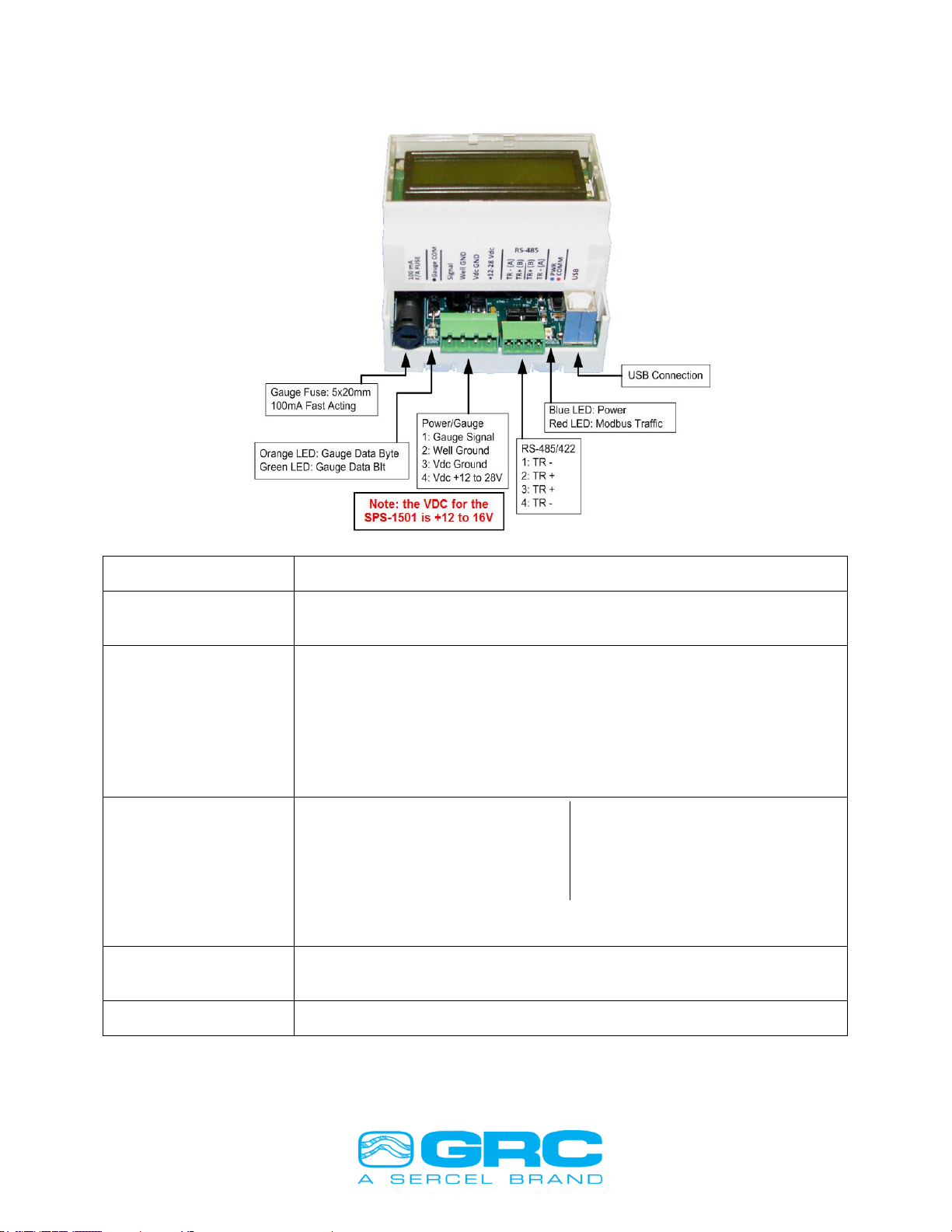
2.0 SPS-1500/SPS-1501 Connections
Gauge Fuse
Gauge signal fuse, 100mA 5x20mm, GRC P/N 043-0047-00
Gauge Comm.
Bi-Color LED
Flashes green for every gauge data bit received
Flashes orange for every gauge data byte received
Power/Gauge
Connections
Gauge Signal
Gauge Signal Return/Wellhead Ground
Vdc Ground
Vdc Power +12v to 28v DC for the SPS-1500 and +12 to 16V for the
SPS-1501
NOTE: Apply torque of 5 inch-pound to secure the wires firmly.
RS-485 / RS-422
Modbus Slave
RS-485: Install (2) Jumpers
1. TR -
2. TR +
3. TR +
4. TR -
RS-422: Remove (2) Jumpers
1. T -
2. T +
3. R +
4. R –
NOTE: Apply torque of 2 inch-pound to secure the wires firmly.
Power/Modbus
Bi-Color LED
Solid blue when power is connected
Blinks red when a Modbus request is received
USB PC Connection
Modbus and firmware updating via USB Virtual COM Port
Figure 1. SPS-1500/SPS-1501 Connections

Doc. No. 006-0202-00 Rev AH 6
3.0 SPS-1500/SPS-1501 LCD
On power-up the SPS-1500/SPS-1501 displays these screens in sequence:
1. Firmware Version/Date Screen
2. Modbus Information
Then the screen cycles through the analyzing steps to acquire the tool, which takes 2-4
minutes. Once the tool is acquired the LCD automatically scrolls through both gauge
readings and diagnostic screens. The display is updated once per second, and the
screen advances every 3 seconds by default.
The displayed data includes the gauge serial number, the latest sensor reading and
Modbus register addresses where that data can be polled from. All enabled parameters
on the tool will be displayed. The screens operate in a loop displaying tool parameters,
then diagnostic screens, and back to tool parameters.
3.1 Status & Diagnostic Screens
There are 8 diagnostic screens that display the status and other useful information
about the SPS-1500/SPS-1501. They are fully customizable with Sercel-GRC’s
DataWorks application or other Modbus editing software –you may enable or disable
screens and also control the scrolling time of the screens. Section 4.5 of this manual
shows how to change the LCD settings.
Firmware Version/Date
Displays the firmware revision and date.
By default this screen is only shown on power up.
Tool Information
Top line: Gauge serial number and gauge type.
Bottom line: Tool baud rate
Modbus Information
Displays the device Modbus baud-rate and slave
address/id
GRC SPS-1500
4.2 9-SEPT-18
1234567 ESP+
ToolBaud: 5.000
Baudrate: 9600
Slave ID: 1
1234567 R40135
Pi: 102.3 PSI
Gauge Serial
Number
Latest Reading
Modbus Register
Address for displayed
value

Doc. No. 006-0202-00 Rev AH 7
Tool Communication Settings
Displays the tool communication settings, described
below:AAn: Auto Analyze ON/OFF
AVlt: Auto Volt ON/OFF
ABd: Auto Baud ON/OFF
BdL: Tool baud low-high limits
Signal Levels
Displays the minimum (Min), average (Now), and
maximum (Max) line current in mA.
Line Voltage
Displays the minimum (MinV), existing (NowV), and
maximum (MaxV) line voltage measured at the surface.
Packet Count and Run Time
Displays the data packet number and elapsed time
since the last power on (displayed as elapsed days,
hours, minutes).
3.2 Status & Error Message
On power up, the SPS-1500/SPS-1501 will go through 16
analyzing steps to find the optimum tool communication
settings. Once the analyze steps are complete, the tool will
send its headers and then begin sending tool readings.
Should an error occur, the error will take precedence over
the scrolling data and be displayed on the screen. If the
error is critical, the board might restart the analyzing steps to
reacquire the tool.
See Appendix 4 SPS-1500 Synchronization and Startup to view the complete startup
sequence.
AAn:ON AVlt:ON
ABd:ON BdL:3-6
Min Now Max
18.2 28.3 28.5
MinV NowV MaxV
55.2 55.7 55.9
RcvDat 435
RunTm:001d18h25m
Stat: Analyze 6
Okay
*** ERROR ***
ESP Framing
m
A
m
A
m
A
Doc. No. 006-0202-00 Rev AH 8
4.0 SPS-1500/SPS-1501 DataWorks Software Configuration
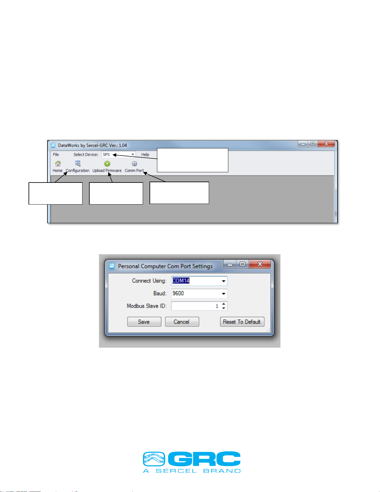
DataWorks by Sercel-GRC is a PC software package for configuration, monitoring, and
troubleshooting the SPS-1500/SPS-1501. Install the software using the installation
program available from Sercel-GRC’s Customer Service. Once the software is installed
connect the SPS-1500/SPS-1501 to the PC using the USB port on the SPS-1500/
SPS-1501. Run the DataWorks program and set up the serial communication port from
the ‘Comm Port’ button as shown in Figure 2. This button will open the ‘Personal
Computer Com Port Settings’ menu. Select the correct Comm Port and Modbus Slave
ID for the SPS-1500/SPS-1501. The default values are shown in Figure 3.
Figure 2. Navigating DataWorks Menu
Figure 3. Communication Port Settings Menu
4.1 DataWorks 1.04 Configuration Menu
Once the SPS-1500/SPS-1501 is configured to communicate with the PC, click on
‘Configuration’ to access different features (as shown in Figure 4).
Comm Port
Settings Button
Configuration
Button
Firmware
Update Button
Select SPS from
Dropdown Box

Doc. No. 006-0202-00 Rev AH 9
Figure 4. DataWorks 1.04 Configuration Menu
The connected gauge serial number is displayed on the ‘Real-Time’ tab. Click on ‘Real-
Time’ to enter the graphing window shown in Figure 5.
The Real-Time graph has the following options:
a) Start/Stop Save for Gauge Data. The gauge data can be saved to a computer in the
form of ASCII format (*.csv file).
b) Graph any parameter on Primary Y-axis.
c) Edit maximum and minimum limits for Primary/Secondary Y-axis.
d) Graph any parameter on Secondary Y-axis.
e) Select between ‘Elapsed Time’ and ‘Real-Time’ on X-axis.
f) Update/Reset. Enter the values in ‘Max:’ and ‘Min:’ fields and click on ‘Update’. The
values can be reset to previously Auto Scaled limits by clicking on ‘Reset’ button.
g) Chart Controls - Enable/Disable Auto Scale. Disabling Auto Scale will allow the user to
change the maximum and lower limits for Y-axis. Enabling Auto Scale will gray out the
maximum and lower limit field.
h) Clear All. This option allows clearing the graph and the data grid as well as stops the
saving of data.
i) Grid Controls - Enable/Disable Auto Scale. With Auto Scale enabled, the cursor will
always point to the latest gauge reading; which appear in the last row of the data grid.
With Auto Scale disabled, the cursor does not point to the current gauge reading; the
user has to scroll through the data grid.
j) Edit Sample Rate (Data Refresh Rate). The Sample Rate controls the data display rate
on the data grid.
k) The chart to plot gauges parameters. All the enabled channels appear in the pull-down
menu of Primary/Secondary Y-axis which can be plotted.
l) Gauge data grid. The gauge enable-channels and High-speed-enable-channels appear
in a grid with a time stamp.

Doc. No. 006-0202-00 Rev AH 10
Figure 5. Real-Time Graphing
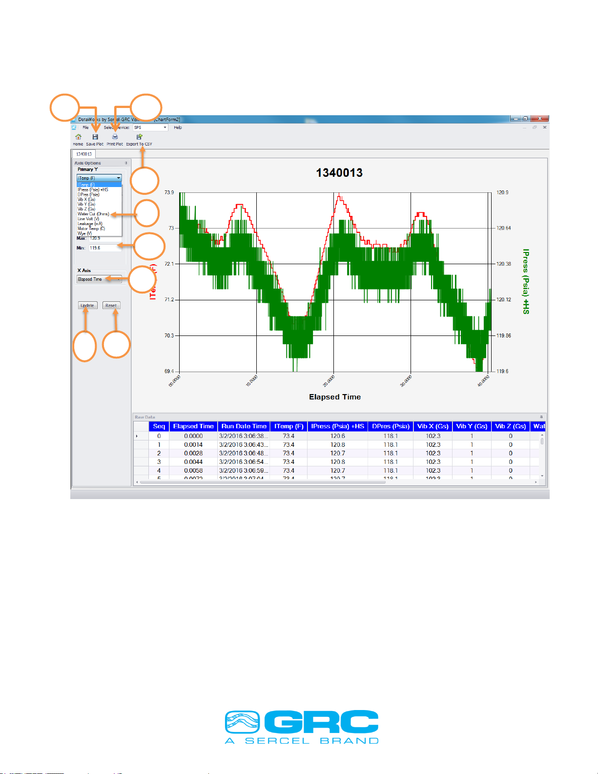
Gauge data can be saved to the computer in ASCII format (*.csv). Click on ‘Start Save’
and select the folder location for the gauge data file. The saved file is automatically
named using the naming convention of ‘Gauge Serial Number Time Stamp’. The gauge
data is being written to the file as long as ‘Stop Save’ button is not clicked. Once the
‘Stop Save’ is pressed, the data recording stops. The saved ‘GaugeSN_timestamp.csv’
file can be opened in DataWorks ‘Real-Time’ window with the following options (see
Figure 6):
a) Save Plot –The active plot on the graphing window with the currently selected
parameter can be saved in *.png format.
b) Print Plot –This feature prints the graph.
c) Export To CSV –The data file can be saved back after data manipulation.
d) Y axis option –Different parameters can be selected across the ‘Primary Y’ and
‘Secondary Y’axis.
e) Max. and Min. Limits –The upper and lower limit for Primary Y-axis and Secondary Y-
axis are adjustable.
f) X Axis –This option allows switching between ‘Real-Time’ and ‘Elapsed Time’. Real-
Time is the time with date and timestamp, and Elapsed-Time corresponds to the total
number of hours through the operation.
b
c
d
e
f
g
h
i
j
k
l
a
Doc. No. 006-0202-00 Rev AH 11
g) Update –Click on ‘Update’ to reflect the newly entered upper and lower limits on the
graph.
h) Reset –This feature resets the previously set upper and lower y-axis limits.
Figure 6. Data Manipulation features from saved gauge data file
4.2 Modbus Communication Map Settings
The Communication Map configures the Gauge Modbus data output from the SPS-
1500/SPS-1501. Figure 7 shows the configuration tables for the communication setting
menu. Most installations will use the default data table. The Communication Map can
change the data type or size for installations located in different regions or with special
requirements. The settings allow the user to customize the Modbus map to meet the
installation requirements.
The Modbus data registers can be shifted anywhere between holding registers 40001-
49999. Changing the Modbus map begins with moving the SPS Holding Register base
g
a
c
b
d
e
f
h

Doc. No. 006-0202-00 Rev AH 12
address. The SPS Holding Register base address value must be 128 registers from the
OEM Holding Register base address.
The default setting for the gauge data parameter range is 40129-40146. To change the
gauge parameter address within this range set the ‘Order’ to the corresponding
address. The software will not allow multiple selections to be set to the same value.
Setting the ‘Order’ to ‘0’ will remove the parameter from the Modbus map and also from
the SPS-1500/SPS-1501 display.
The ‘OEM Map’ has the following configurable options:
a) Order –The ‘OEM Register Parameter’ is mapped to any ‘Reg Map’ Modbus registers
by changing the ‘Order’ via clicking the up and down arrows.
b) Dec Pts –The decimal places on any gauge parameter are changed by clicking the up
and down arrows; adjustable up to 3 decimal places.
c) Unit –The units for the gauge parameter are selectable via a pull-down menu.
d) Length –The bit length for each available ‘OEM Register Parameter’ is selectable
between 16 and 32 via the up and down arrows. If Serial Number is selected for 16-bit,
then the Real-Time will show ‘65536-Real-Time’ instead of ‘Gauge Serial-Number Real-
Time’.
Figure 7. Modbus Communication Map Menu
To set the gauge data parameter range to another range, determine the OEM Holding
Register Base address. This will be the lowest register value of the custom Modbus
map. Once this value is determined use the scroll boxes for the OEM Holding Register
to set this value, then set the SPS Holding Register Base address value to at least 128
registers higher or lower than the OEM Holding Register value. The software will not
write Base address values inside the 128 register limit to the SPS-1500/SPS-1501. After
c
a
b
d
Doc. No. 006-0202-00 Rev AH 13
the value is selected click the Parameter in the left column to retain the setting. Once all
the values are set, click the ‘Send to Unit’ button to write the configuration to the SPS-
1500/SPS-1501. Contact Sercel-GRC Customer Service for additional information on
map configuration.
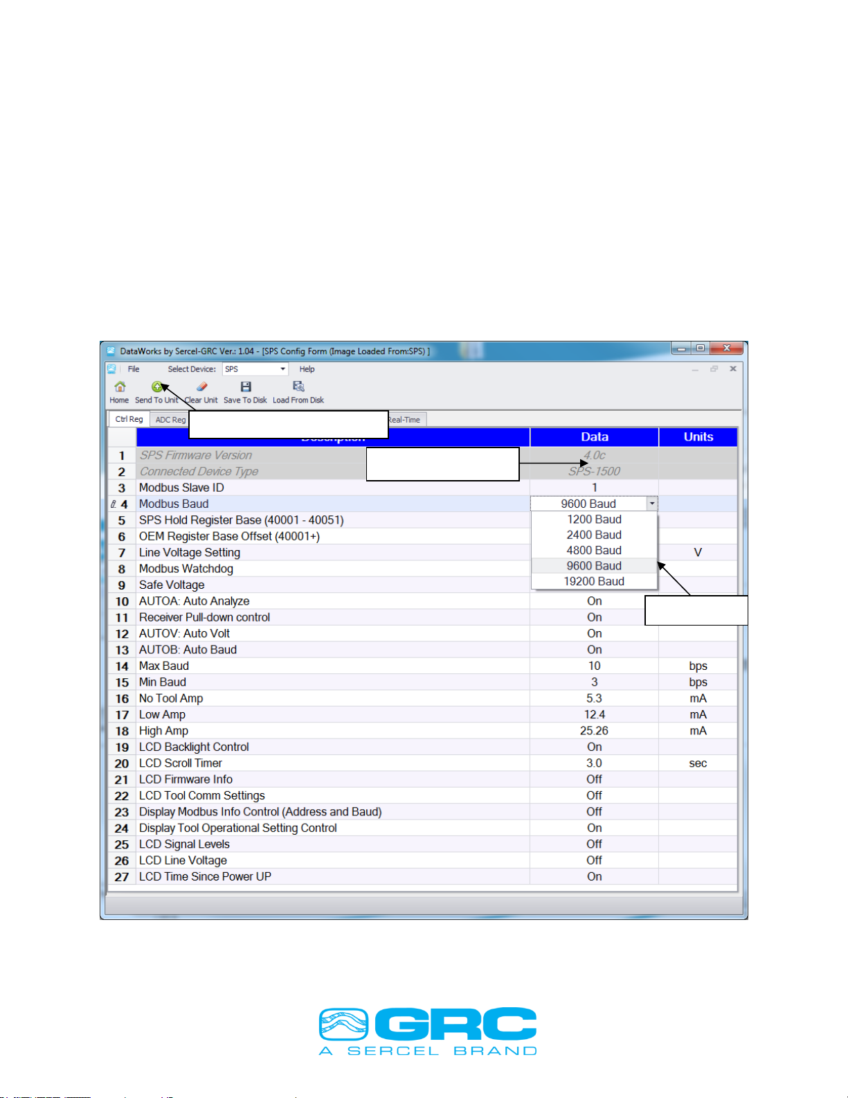
4.3 Modbus Slave ID & Baud Rate Settings
The ‘Ctrl Reg’ tab has several adjustable configuration settings that can be executed in
the SPS- 1500/SPS-1501. The Modbus Slave ID is selectable in the range 1 thru 254.
The Modbus Baud Rate is selectable from the pull-down menu. Once the desired
Modbus slave ID and baud rate have been selected, click on ‘Send to Unit’ to write the
configuration to the SPS- 1500/SPS-1501 (see Figure 8). These settings are saved on
the EEPROM of SPS- 1500/SPS-1501, so the settings are retained in the next power
up.
Figure 8. SPS Control Register Settings
Send to Unit Button
Baud Rate
Modbus Slave ID

Doc. No. 006-0202-00 Rev AH 14
4.4 SPS Configuration Settings
The SPS-1500/SPS-1501 controller board is configured from the factory to
automatically detect the optimum signal and voltage settings for gauge communication.
Some instances may require adjusting the communication settings due to noisy
environments, longer wire lengths or other issues that can cause communication
problems. DataWorks will automatically detect the SPS configuration and display the
current settings. To make changes to the SPS configuration select the parameter to
change and make the change using the scroll box. Once all the changes are made click
the ‘Send to Unit’ button.
Cycle SPS-1500/SPS-1501 power to complete SPS configuration changes.
The function ‘Save to Disk’ saves the SPS-1500/SPS-1501 control register’s
configurations. Once all the desired settings are done, click on ‘Save to Disk’ and the
window opens up to input a configuration file name. The saved configuration file can be
retrieved and loaded back into DataWorks using the function ‘Load From Disk’.
4.5 SPS Manual Operation
The SPS-1500/SPS-1501 is designed to automatically detect and operate at optimum
levels of communication. The device also has built-in features to protect the electronics
from damage. To change the operating modes of the SPS-1500/SPS-1501 select the
Configuration register and use the scroll box for the parameter to change the value. The
Scroll box will limit the value to the range for the specific register. The LCD configuration
can be set using the SPS configuration screen (see Figure 9 for LCD options).
To enable the Manual mode switch the Auto Volt and Auto Analyze off. This will set the
line voltage to the Power On Voltage value. To increase the line voltage change the
data value to the set voltage required (Min 40V - Max 80V).
Auto Baud sets the tool communication rate to the maximum rate the line conditions will
allow. Setting the Min and Max Baud to open the range can eliminate Baud rate errors
from the tool. It is common to see ‘Baud Fast’ or ‘Baud Slow’ errors during the line
analysis. The setting should only change as described in the troubleshooting section of
this manual.
The Modbus Watchdog feature monitors the SPS-1500/SPS-1501 Modbus port for
communication packets. When the SPS-1500/SPS-1501 receives a valid Modbus
packet a timer starts and if the unit does not receive another valid Modbus packet within
5 minutes the unit will reset. If the SPS-1500/SPS-1501 never receives a Modbus
packet the unit runs without starting the timer.
Safe Voltage will prevent the SPS-1500/1501 from running if a high line imbalance is
detected on the gauge input line. This protects the electronics from overloading the
signal when trying to operate over the imbalance (does not apply to the SPS-1501).

Doc. No. 006-0202-00 Rev AH 15
SPS Control
Description
Default
Power On Voltage Setting
Sets initial Line Voltage at startup
40.00
MBWD:Modbus Watchdog
Enables 5 Min Modbus packet timer
on
SAFEV:Safe Voltage
Measures Signal Levels before gauge power on
on
Auto Volt
Sets optimum line voltage
on
Auto Analyze
Analyzes for optimum line communication
on
Auto Baud
Toggle Auto Baud
on
Minimum Baud Rate
Edit Minimum tool baud rate
3
Maximum Baud Rate
Edit Maximum tool baud rate
6
Line Voltage Tolerance
Edit Line Voltage Tolerance
4
Low Current
Edit low current threshold
13-14
High Current
Edit high current threshold
24-25
LCD Backlight
Toggle LCD backlight
on
LCD Time
Adjust time between data screens
3
LCD Firmware Information
Toggle Display: Firmware Version
off
LCD Tool Information
Toggle Display: Tool Information
on
LCD Modbus Information
Toggle Display: Modbus Information
on
LCD Wye Imbalance
Toggle Display: Wye Voltage Imbalance
on
LCD Comm Settings
Toggle Display: SPS Communication Settings
on
LCD Signal Levels
Toggle Display: SPS-Tool Signal Levels
on
LCD Line Voltage
Toggle Display: Current Line Voltage
on
LCD Run Time
Toggle Display: SPS-1500/SPS-1501 Power On
Time
on
Figure 9. SPS Configuration Control Settings
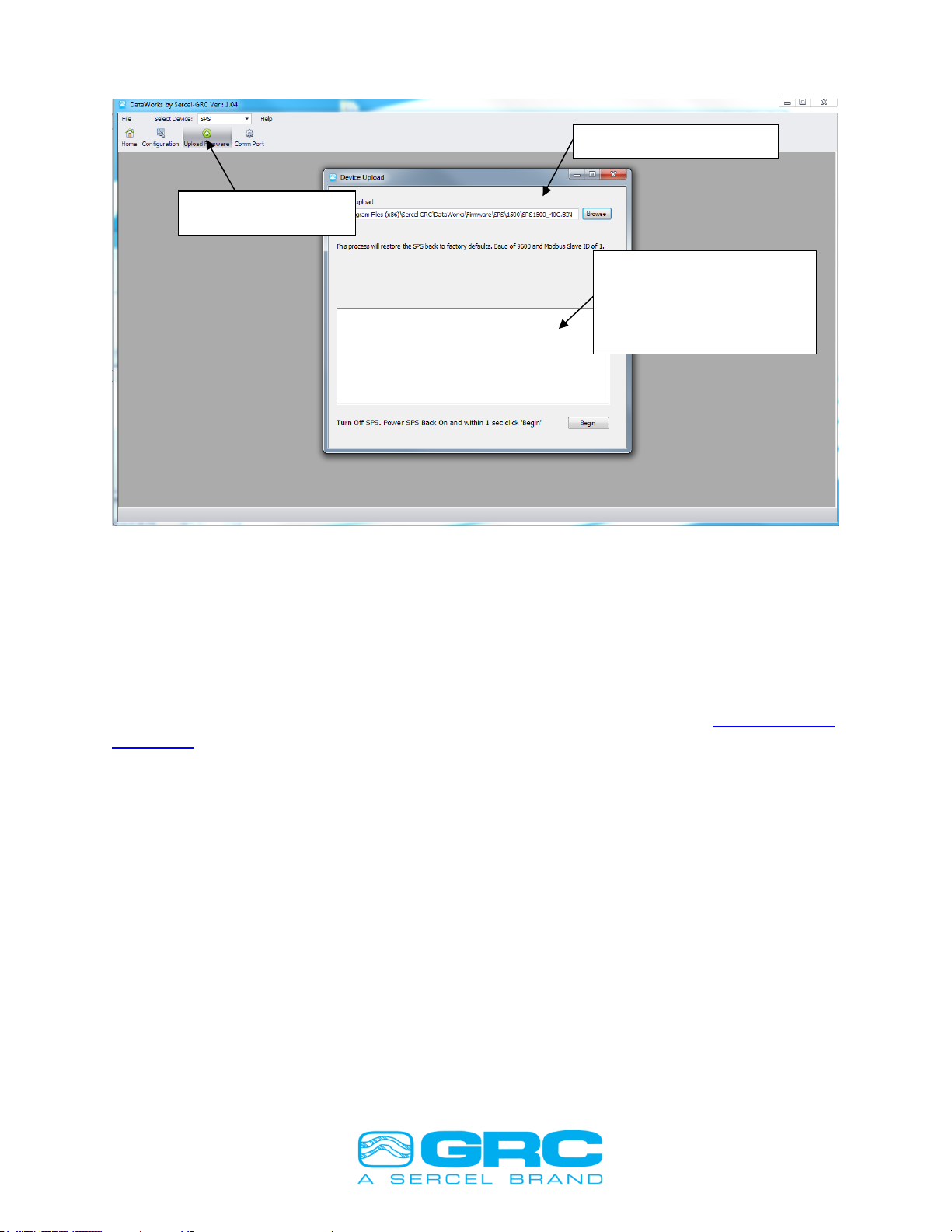
4.6 Firmware Update
To update the SPS-1500/SPS-1501 firmware version, connect the device to a PC as
described in section 4.0. Click the ‘Upload Firmware’ button on the DataWorks Home
Screen menu as shown in Figure 10. Verify the Comm Port by clicking ‘OK’ on the SPS
Connect window and the Upload Firmware screen will open.
Click the ‘Browse’ button to select the location of the firmware file. When the file is
selected begin the update process by cycling the power to the SPS-1500/SPS-1501
immediately after clicking the ‘Begin’ button. The power must cycle within 1 second of
sending the ‘Begin’ command. This time period allows the Bootloader to detect the file
transfer. Once the firmware upload is completed the SPS-1500/SPS-1501 will return to
normal operation.
Note: The SPS-1501 will not communicate with the C-4001T if SPS-1500 firmware
is uploaded. Use only firmware designed for the SPS-1501. The same is true for
the SPS-1500. Only use firmware designed for the SPS-1500 or it will not
communicate with the ESP gauge line.
Doc. No. 006-0202-00 Rev AH 16
Figure 10. Uploading Firmware in DataWorks
5.0 ESP ‘E’ Series Sensor Configuration
Sercel-GRC ESP-2500 and ESP-3500 Models are available in an ‘E’ series. The ‘E’
series will include a Two-Way Configuration feature. This option allows the user to
Enable or Disable ESP Sensor parameters and to configure the Downhole Sensor to
communicate at a higher speed data rate using the SPS-1500/1501 and DataWorks
Software. Contact Sercel-GRC Sales for ‘E’ Series Gauge information at sales@Sercel-
GRC.com
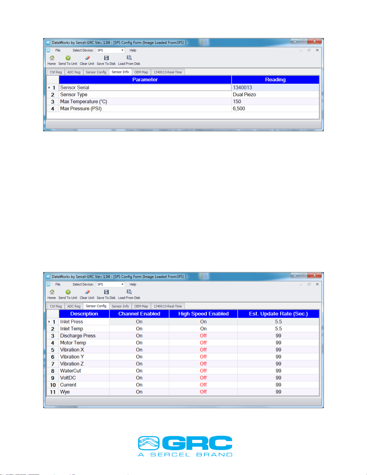
To utilize the features available on the ‘E’ Series gauge, allow the SPS-1500/1501 to
established data communication with the ‘E’ Series Downhole Sensor. Once
communication is established, DataWorks software will display two additional tabs when
the user is on the ‘Configuration’ page. The additional tabs are labeled ‘Sensor Config’
and ‘Sensor Info’, as shown in Figure 11.
Firmware Update
Select Firmware File
Turn off power to SPS.
Re-Apply Power and
immediately press
‘Begin’
Doc. No. 006-0202-00 Rev AH 17
Figure 11. Sensor Information Window
To configure any parameter to transmit data at the high-speed data rate, or to enable or
disable any available sensor parameter, click on the Sensor Config tab. Unavailable
parameters will be shaded in gray and text will be in italics.
To enable/disable sensor parameters, click on the desired parameter under ‘Channel
Enabled’ and select ‘Off’ or ‘On’ from the drop-down box as shown in Figure 12.
‘Off’ will disable the selected channel and the downhole sensor will no longer send data
for the selected parameter to the surface unit. When all desired changes have been
made, click the ‘Send to Unit’ button to send the configuration to the downhole sensor.
To set sensor parameters to transmit at the high speed’ data rate, click on the desired
parameter under ‘High-Speed Enabled’ and select ‘Off’ or ‘On’ from the drop-down box.
When all desired changes have been made, click the ‘Send to Unit’ button to send the
configuration to the downhole sensor.
Figure 12. Sensor Configuration Window

Doc. No. 006-0202-00 Rev AH 18
After clicking on the ‘Send to Unit’ button, the software will give the message: ‘Do you
wish to send the Sensor Configuration?’. Click yes to send the configuration to the
downhole sensor, shown in Figure 13.
The SPS-1500/SPS-1501 will restart and give the following display messages:
Power Off
Sync Phase 3
Sync Phase 4
Sync Phase 5
Checking Tool
Programming Tool
Tool Response
Tool Configured!
Rcv Hdr 0
Rcv Hdr 1
Rcv Dat1
Figure 13. Send Sensor Configuration Message
Selecting ‘No’ to this message will only send changes made to the ‘Config Coils’ tab and
the ‘Ctrl Reg’ tab, but will not send any sensor configuration to the downhole sensor.
Selecting ‘Cancel’ to this message will not send any changes to the SPS-1500/SPS-
1501.
The Parameter Enable/Disable channel and High-Speed Enable/Disable configurations
that are sent to the downhole sensor will be saved in the SPS-1500/1501 and resent to
the sensor in the event of a power loss. To return the sensor to the factory default
configuration, click the ‘Clear Unit’ button. This will re-enable all default sensor
parameters and reset all high speed channels to standard mode.

Doc. No. 006-0202-00 Rev AH 19
6.0 High Speed Operation
High Speed operation can be configured on any available sensor channel. The
channel(s) that are set to ‘High Speed’ will update at a higher sample rate than the
standard mode. Update Rates for various sensor configurations are shown in Figure 14.
High Speed enabled channels will display ‘HS’ beside the Modbus register on the SPS-
1500/SPS-1501 LCD. While running ‘Real Time’ via DataWorks software, a High Speed
channel will be displayed +HS on the enabled channels column heading (see Figures
15 and 16).
ESP Gauge
High Speed Mode
Configuration (High Speed
Parameters Enabled)
*High Speed Update
Rate for Selected
Parameters (Seconds
to next update value)
**Full Rate for
remaining parameters
(Seconds to next
update value)
ESP-2500
Standard
None
30
ESP-3500
Standard
None
35
ESP-2500/3500
Intake Pressure
ONLY
2.5
none
ESP-2500/3500
Intake Pressure
Intake Temperature
ONLY
4.5
none
ESP-2500/3500
Intake Pressure
Intake Temperature
Motor Temp
ONLY
6.5
none
ESP-2500
Intake Pressure
(All other parameters at Full
Rate)
4
60
ESP-2500
Intake Pressure
Intake Temperature
(All other parameters at Full
Rate)
6
72
ESP-2500
Intake Pressure
Intake Temperature
Motor Temp
(All other parameters at Full
Rate)
8
80
ESP-3500
Intake Pressure
(All other parameters at Full
Rate)
4
76
ESP-3500
Intake Pressure
Discharge Pressure
(All other parameters at Full
Rate)
6
126
ESP-3500
Intake Pressure
Discharge Pressure
Intake Temperature
(All other parameters at Full
Rate)
8
144
ESP-3500
Intake Pressure
Discharge Pressure
Intake Temperature
Motor Temperature
(All other parameters at Full
Rate)
10
150
Figure 14. ‘High Speed’ Data Rates

Doc. No. 006-0202-00 Rev AH 20
Figure 15. ‘High Speed’ Enabled Channel Display
Figure 16. ‘High Speed’ DataWorks Display
High-Speed Enabled
Channel shows ‘+HS’ in its
Column Header
This manual suits for next models
1
Table of contents
Other Sercel Measuring Instrument manuals


Popular Measuring Instrument manuals by other brands

Vemer
Vemer ENERGY-400 D90 user manual

Greiner Vibrograf
Greiner Vibrograf Magnotest II operating manual

Agilent Technologies
Agilent Technologies U2722A user guide

Master Meter
Master Meter Allegro installation guide

ACS contsys
ACS contsys DAL-311x3x0S operating instructions

Hilti
Hilti pd-e Operating instruction


