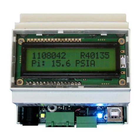
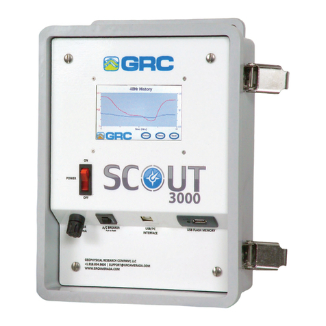
Sercel GRC ESP-Series User manual

1
a
Field
Installation
Manual
ESP
MONITORING
SYSTEMS

Doc No. 006-0211-00 Rev AK Page 1 of 33
ESP MONITORING SYSTEMS
FIELD INSTALLATION MANUAL
Gauges:
ESP-1500, ESP-2500, ESP-3500, Spy Pro
Surface Equipment:
SPS-1500, Scout-3000, Data Pro
NOTICE
This manual is intended for private information only, with the understanding that any
other use of the subject matter, in whole or in part, by reference or otherwise, shall be
only with the prior knowledge and approval of Sercel-GRC Corp, and with the further
understanding that this manual is for informational purposes only and that suggestions
and recommendations contained herein shall not be understood or construed as a
guarantee or warranty of any method, product or device.
Federal copyright law protects the publication. No part of this publication may be copied
or distributed, transmitted, transcribed, stored in a retrieval system, or translated into
any human or computer language, in any form or by any means, electronic, magnetic,
manual or otherwise, or disclosed to third parties without the express written permission
of Sercel GRC Corp.
Any questions concerning the content of this manual, equipment operation, field
maintenance, maintenance assistance and operation or maintenance training courses
should be directed to Sercel-GRC.
Copyright © 2014-2017 by Sercel-GRC Corp.
All rights reserved worldwide.
Document Number: 006-0211-00
Sercel-GRC Corp.
13914 E. Admiral Place, Ste. B
Tulsa, OK 74116-2107 USA
Telephone: (1) 918-834-9600 / Fax: (1) 918-838-8846
Visit our web page at www.Sercel-GRC.com

Doc No. 006-0211-00 Rev AK Page 2 of 33
Table of Contents
INTRODUCTION.............................................................................................................3
ESP Downhole Gauge Pressure Measurement.................................................................. 3
Surge panel and surface choke.......................................................................................... 3
Surface interface................................................................................................................ 3
Customer Service/Support...........................................................................................4
BENCH TESTING AND VERIFICATION PROCEDURES..............................................5
Tools Required................................................................................................................... 5
Process Steps for Bench Test and Verification................................................................... 5
Process Steps for Insulation Test with Megger Tester (Fluke 1550C) on Surface............... 6
Process Steps for Resistance Test with Analog Type Meter (Simpson 260) on Surface..... 6
INSTALLATION PROCEDURES FOR DOWNHOLE GAUGE.......................................7
Installing the ESP Sensor with WYE Point Adapter to the Motor ........................................ 7
Installing the Resistance Temperature Detector “RTD” ...................................................... 9
Installing the ESP Sensor with Single Wire to the Motor....................................................12
Discharge Port Connection (ESP-3500 only).....................................................................14
Discharge Port Connection (Spy Pro only)........................................................................15
Testing the ESP Sensor While Installing Tubing......................................................16
Megger testing motor and cable........................................................................................16
INSTALLING THE SURFACE INTERFACE EQUIPMENT...........................................17
Wiring Detail......................................................................................................................17
ESP Gauge and Surface Control Interface Diagram Components.........................17
INSTALLING THE SURGE SUPPRESSOR AND SURFACE CHOKE........................18
Surface Choke ..................................................................................................................18
Surge Panel Protector/Suppressor....................................................................................19
Surface Choke and Surge Protector Panel Assembly........................................................21
APPENDIX 1.................................................................................................................22
TROUBLESHOOTING ......................................................................................................22
Sensor to Surface Communication Troubleshooting..............................................22
APPENDIX 2.................................................................................................................23
SCOUT and SPS Error Codes and Corrective Actions......................................................23
APPENDIX 3.................................................................................................................25
ESP Monitoring System Field Checklist.............................................................................25
APPENDIX 4.................................................................................................................26
Surface Read Out Device Specifications...........................................................................26
SPS-1500...............................................................................................................26
Scout-3000.............................................................................................................27
Data Pro.................................................................................................................28
APPENDIX 5.................................................................................................................29
ESP Sensors - Pass/Fail Criteria.......................................................................................29
ESP Sensors –Simpson Test Pass/Fail Criteria ...............................................................30
ESP Sensors –Megger Test Pass/Fail Criteria .................................................................31
APPENDIX 6 SPS-1500 Synchronization and Startup..............................................32

Doc No. 006-0211-00 Rev AK Page 3 of 33
INTRODUCTION
This field installation manual will explain in detail the operation and installation of all
Sercel-GRC ESP Monitoring Systems. ESP gauge instructions are for the following
gauge models: ESP-1500, ESP-2500, ESP-3500, and Spy Pro.
ESP Downhole Gauge Pressure Measurement
The intake pressure measures the pressure inside the motor housing. Motor oil protects
the intake pressure port from well fluid contamination.
The discharge pressure measures the pressure at the pump discharge port via a
hydraulic line connection to the discharge port on the pump. This connection is available
only on Dual Pressure gauges such as the ESP-3500, and Spy Pro 9 and 11.
Surge panel and surface choke
Surface interface
For detailed surface interface instructions, refer to:
Scout-3000 Field Operation Manual PN: 006-0191-00
SPS-1500 Operation Manual PN: 006-0202-00
Data Pro Operations Manual PN: 10029355
A system installation checklist is shown in APPENDIX 3of this manual. This checklist
will provide the installer with the ability to follow and record the installation of the
monitoring system. Please follow this guide and use the checklist provided when
installing all ESP Sensor Systems.

Doc No. 006-0211-00 Rev AK Page 4 of 33
Customer Service/Support
If assistance is needed, please contact one of our centers listed below. The engineers
and technicians will be more than happy to provide you with any assistance needed.
SITE
LOCATION
PHONE
EMAIL
Tulsa, USA
6540 E. Apache Street
Tulsa, OK 74115 USA
+1.918.834.9600
Dubai, UAE
Jebel Ali - Free Zone
Dubai, UAE
+971 4 8832142

Doc No. 006-0211-00 Rev AK Page 5 of 33
BENCH TESTING AND VERIFICATION PROCEDURES
Note: Bench test and verification procedures are applicable to all ESP sensors.
Tools Required
Power Supply 110 VAC/12-24VDC
Surface Readout (Scout-3000, SPS-1500, Data Pro, Field Test Box)
Signal and Ground wires
Alligator Clips
Simpson 260 analog type meter
Fluke 1550C insulation tester
Process Steps for Bench Test and Verification
1. To prevent injury, proper PPE should always be worn. Use caution when
working near or handling equipment. Utilize proper lifting techniques to
prevent injuries to personnel or equipment.
2. Remove the top shipping cap from the ESP Sensor.
3. Connect a signal wire from the Surface Readout to the signal wire on the
sensor Figure 1, or if using a WYE Point adapter connect to one of the three
pins inside the WYE adapter Figure 2. Connect the ground wire to the sensor
housing. Connect a motor RTD to the two white motor temperature wires.
4. Power on the Surface read out.
5. Data will display on the Surface Readout in approximant 2-5 minutes.
6. Record the parameter readings on the ESP Sensor Checklist; APPENDIX 3of
this manual, for test verification records.
7. ESP Sensor Pass/Fail Criteria is shown in APPENDIX 5.
8. See APPENDIX 6SPS-1500 Synchronization and Startup for the complete
SPS-1500 startup sequence.
Figure 1: I-Wire Connection Figure 2: WYE Connection
Signal Wire
Ground Wire
Motor RTD
Wires
Signal Wire
Motor RTD
Wires
Ground Wire

Doc No. 006-0211-00 Rev AK Page 6 of 33
Process Steps for Insulation Test with Megger Tester (Fluke 1550C)
on Surface
9. Connect the Megger Tester in reverse polarity by connecting the red wire to the
housing of the gauge and the black wire to the signal pin.
10.Apply voltage for 30 second duration.
11.ESP Sensor Megger Pass/Fail Criteria is shown in APPENDIX 5.
NOTE: MEGGER TEST THE SENSOR IN REVERSE POLARITY ONLY!!
LIMIT MEGGER VOLTAGE TO 5KV MAX
Process Steps for Resistance Test with Analog Type Meter (Simpson
260) on Surface
12.Connect the Analog Multimeter (on Rx10,000) in forward polarity by connecting
the black wire to the housing of the gauge and the red wire to the signal pin.
13.ESP Sensor Simpson Pass/Fail Criteria is shown in APPENDIX 5.

Doc No. 006-0211-00 Rev AK Page 7 of 33
INSTALLATION PROCEDURES FOR DOWNHOLE GAUGE
Installing the ESP Sensor with WYE Point Adapter to the Motor
It is recommended that the sensors be installed in a controlled environment or shop
prior to being sent to the field. If a sensor must be installed in the field follow the
procedures outlined below for sensors equipped with WYE point adapters.
1. Layout the sensor so that the three female connections on the Hockey puck
are aligned with the three pins coming out of the motor, and the holes on the
motor base are aligned with the holes on the motor head as shown in FIGURE 3.
2. Insure the O-ring has no sign of damage and install or replace with a new
O-ring if there are any signs of damage.
Figure 3: Aligning the motor pins to the Hockey Puck
3. Carefully stab the sensor into the motor, watching closely that the three pins
mate up with the three female connections on the hockey puck. IT IS VERY
IMPORTANT DURING THIS STEP YOU DO NOT TWIST THE SENSOR
WHILE STABBING INTO THE MOTOR BASE. DOING SO WILL RESULT IN
DAMAGING THE HOCKEY PUCK AND RUINING COMMUNICATION TO
THE SENSOR ONCE THE MOTOR IS STARTED.

Doc No. 006-0211-00 Rev AK Page 8 of 33
Figure 4: Gauge Stabbed into the Motor Base
4. Once the sensor has been stabbed as far as shown in FIGURE 4, finger-tighten
two of the motor base bolts at the top and bottom of the sensor to help support
the sensor weight. DO THIS BEFORE PROCEEDING TO STAB THE
SENSOR FULLY INTO THE MOTOR BASE.
5. Fully insert the sensor into the motor base making sure not to cut or pinch the
O-ring.
6. Install reaming bolts torque to minimum 25ft-lbs to insure proper seal.
7. To fill the sensor with oil, use either the drain and fill valve located at the
bottom of the sensor or through the drain and fill valve located on the motor.
Item
#
Part Number
Description
1
089-0252-00
PLUG, VENT & DRAIN
2
089-0254-00
GASKET, VENT & DRAIN
LEAD SEAL
3
089-0251-00
VALVE, DRAIN & FILL
4
089-0253-00
GASKET, LEAD SEAL
Table 1: Drain and Fill Valve Part Numbers
Note: Both gaskets (Items 2 and 4) listed above are single-use components.
Item 3 (valve) should be torqued to 210 in-lbs, and Item 1 (plug) should be torqued to
100 in-lbs.
8. After the sensor is installed verify sensor readings using a Surface Readout
and record the values on the ESP Sensor Checklist APPENDIX 3.

Doc No. 006-0211-00 Rev AK Page 9 of 33
Installing the Resistance Temperature Detector “RTD”
All ESP Gauges monitor Motor Temperature with a Platinum 1K RTD. There are
several RTD Motor Temperature Probe options including Probe, Threaded, and
customer supplied. Motor Temp probes are mounted inside the gauge assembly and
placed against the Motor Windings for maximum temperature transfer and fast
response. Motor Temperature Sensors can be ordered as an accessory or wired
permanently inside the gauge eliminating field connection concern. The factory installed
RTD is a Probe Style RTD with a stainless steel shielded sheath.
Also included in this document is the wye point solder procedure that Manufacturing
uses.
Motor RTD Connection Instructions (Spy Pro only - Factory Installed)
Since the RTD is factory installed. Determine where to place the RTD in the base
of the motor. The shielded RTD cable can be coiled inside the motor base.
Remember to keep the wire away from the motor shaft to prevent damage to the
RTD cable.
Motor RTD Connection Instructions (ESP-1500/2500/3500)
1. The first step is to determine where the RTD is going to be placed. It can be
either inside the ESP motor oil passage or inside the Sercel-GRC gauge. Inside
the gauge is the safest and is the least likely to come in contact with rotating
motor components. But it will be slower in responding to temperature variations
of the ESP motor. Placing the RTD inside the motor oil passages provides faster
response times to temperature changes, but runs the risk of making contact with
rotating parts.
2. Shorten the two wires coming from the gauge for the RTD to match where you
have determined to place the RTD. If it’s going inside the motor oil passage
secure the wiring and its excess to insure that the RTD is not drawn further into
the oil passage by the oil flowing through it. This prevents the RTD from coming
in contact with the rotating internal parts of the motor. Also insure that the wiring
will not come in contact with the end of the rotating motor shaft located where the
motor and ESP gauge are mated together. If the RTD is being placed inside the
gauge do not coil up the excess wire inside gauge but instead shorten the wires
and then insert the RTD and wiring back into the gauge. The reason for not
coiling the excess wire up and placing it inside the gauge is this can possibly
allow motor noise to show up on the motor temperature readings.
3. Strip 1/4” to 3/8” of insulation from the RTD and gauge wires.
4. Cut a piece of high temp heat shrink tubing, around 2.5”, and slide it over and
past both stripped gauge wires.
5. Using two more pieces of high temperature heat shrink tubing, around 1.5” long,
slide each piece over and past each individual gauge wire. The result should look
like the example in FIGURE 5.

Doc No. 006-0211-00 Rev AK Page 10 of 33
Figure 5: Three Pieces of Shrink Tubing on the Gauge Wires
6. Twist one RTD wire and one RTD gauge wire together creating a splice so that it
appears as a straight wire and not two wires side by side. At this time solder the
two wires together using high temp solder. Do the same step for the other two
wires (one from the RTD and the other from the gauge).
7. Slide the heat shrink tubing down over each individual soldered bare wire and
heat shrink the two pieces of tubing using a hot air gun (heat gun). The solder
joint should be located in the center of the length of the tubing and the result
should appear as shown in FIGURE 6.
Figure 6: Long Piece of Heat Shrink Tubing Over Both Wires
8. Slide the longer piece of heat shrink tubing over both wires so that the solder
joint is centrally located inside the tubing as shown in FIGURE 7.

Doc No. 006-0211-00 Rev AK Page 11 of 33
Figure 7: Heat Shrink Tubing Over the Solder Joints
Finally, replace the wye point if you have removed it. Attach the Scout-3000 or portable
Scout to any of the motor terminals of the wye point or to the gauge wire if not using our
wye point. Turn on the Scout and check/record gauge readings.
Place the RTD in the position you had determined and reassemble the gauge and
motor. Re-check and record readings using the Scout attached to the top of the motor
on one motor lead.
Solder joint located
at the center of the
heat shrink tubing.

Doc No. 006-0211-00 Rev AK Page 12 of 33
Installing the ESP Sensor with Single Wire to the Motor
It is recommended that the sensors be installed in a controlled environment or shop
prior to being sent to the field. If a sensor must be installed in the field follow the
procedures outlined below for sensors equipped with single signal pin.
Spy Pro gauges are pre-wired with a connector pigtail adapter and waterproof boot seal
attached to the gauge signal pin (see illustrations below). For optimum performance,
connect the motor WYE point or I-Wire directly to the gauge pin. This will require
removal of the gauge motor head adapter (if fitted) to access the I-Wire pin on the
gauge and re-fit of the motor head adapter. If the motor head adapter is removed, re-
torque the head as required for your application.
1. Connect the male end connector by fully inserting into the female connector from
the motor I-Wire. FIGURE 8
Figure 8: Connect the Motor I-Wire to the Gauge
2. Neatly bundle the RTD and signal wires and secure using high-temperature zip ties.
FIGURE 9
Figure 9: Bundle the Wires and Zip Tie
3. Slide the wire bundle into the head of the gauge. FIGURE 10

Doc No. 006-0211-00 Rev AK Page 13 of 33
Figure 10: Slide Wire Bundle into the Head of the Gauge
4. Lubricate the O-rings. Carefully stab the sensor onto the motor. Care must be taken
to NOT PINCH the wires or damage the O-rings.
5. Insert the top and bottom bolt and finger tighten. FIGURE 11
6. Insert remaining bolts and tighten all bolts to 25 ft/lbs.
Figure 11: Insert Top and Bottom Bolts
7. Perform bench testing through the pothead using GRC surface readout. FIGURE 12
Log the data to the ESP Sensor Checklist (Appendix 3)
Figure 12: Bench Test Through the Pothead

Doc No. 006-0211-00 Rev AK Page 14 of 33
Discharge Port Connection (ESP-3500 only)
Figure 13: Discharge Tubing Connection
THIS OPERATION NEEDS TO BE COMPLETED IN ITS ENTIRETY BEFORE THE
MLE IS CONNECTED TO THE MOTOR.
1. Pre-fill the discharge tubing with dielectric oil by using a hydraulic hand pump to pump oil
into the tubing until there is a steady flow coming out the opposite end.
2. Cap off the ends of the discharge tubing to ensure oil remains inside.
3. Remove the fitting and ensure that the NPT threads have been Teflon taped.
4. Install the NPT fitting back into the base.
5. Remove the compression nut and ferrules from the fitting and capped off discharge
tubing.
6. Install compression nut and ferrules onto the capillary tubing ensuring the correct
ferrule orientation.
7. Place the capillary tubing with nut and ferrule into the fitting and hand tighten nut then
using a 9/16” wrench tighten the nut 1-1/4 more turns.
8. Remove the NPT plug directly above the NPT fitting.
9. Remove the capped off end of discharge tubing and reconnect to hydraulic hand pump.
10. Pump oil through the discharge tubing until a steady stream of oil without bubbles is
flowing through discharge pressure bleed port.
11. Reapply Teflon Tape to NPT plug and reinstall the NPT plug back into the pressure
bleed port.
12. Band the discharge line~6in above the pressure bleed port and then every 3ft to the top
of the ESP.
13. Nipple up the discharge sub.
14. Cut the discharge line to appropriate length and install into the velocity fuse fitting.
15. Tighten velocity fuse using a 9/16” wrench tighten the nut 1-1/4 more turns after hand
tight.
Compression Fitting
1/8” NPT to ¼” inch
capillary tubing
Discharge
Pressure Bleed
Port Plug
Must be
INSTALLED
before running
gauge into the
well.

Doc No. 006-0211-00 Rev AK Page 15 of 33
Discharge Port Connection (Spy Pro only)
Follow the steps below to attach the Discharge Port Tubing on the Spy Pro gauge.
Illustration of plastic retainer and
Hydraulic fitting. Do not remove
the fitting. If removed, parts must
be placed in order.
Tighten fitting finger tight and
then remove plastic retainer.
Insert tube into fitting until firmly
seated against shoulder inside
pressure head.
Tighten nut to 25 ft•lbs. Or,
tighten nut finger tight, mark
the nut, and tighten nut one full
revolution.
Figure 14 Spy Pro Discharge Port connection

Doc No. 006-0211-00 Rev AK Page 16 of 33
Testing the ESP Sensor While Installing Tubing
Megger testing motor and cable
The motor and cable may be Megger tested if required using the following guidelines:
The output voltage of a Megger will exceed the breakdown voltage of the protective
MOV mounted on the fuse block. The MOV will conduct if a Megger is used, giving
incorrect readings. Disconnect the three-phase choke and fuse block from the motor
cable before testing. Do not Megger test the downhole equipment while any of the
surface components are connected to the motor power cable.
NOTE: MEGGER TEST THE SENSOR IN REVERSE POLARITY ONLY!!
LIMIT MEGGER VOLTAGE TO 5KV MAX
Follow the steps below to test the gauge through the ESP cable spool once the cable
has been connected to the motor.
Since the SCOUT is powered by 110 VAC, an external power supply will be
needed.
ONLY CONDUCT THIS CHECK WHILE THE SPOOL IS NOT MOVING.
NEVER AT ANY TIME STEP OVER THE 3 PHASE ESP CABLE.
1. Connect the signal wire to one of the exposed copper conductors on the 3 phase
ESP cable.
2. Connect the ground wire to the exterior lead shielding of the ESP cable.
3. Power on the Surface Readout.
4. Record the parameter readings on the ESP Sensor Checklist given in the
Appendix of this Manual.
5. It is recommended to continue monitoring the sensor by verifying downhole
sensor readings with a Sercel-GRC Surface Readout approximately every 1000ft
(~33 joints).
Figure 15: Spooling Unit

Doc No. 006-0211-00 Rev AK Page 17 of 33
INSTALLING THE SURFACE INTERFACE EQUIPMENT
Wiring Detail
FIGURE 16 shows a typical wiring and installation schematic for the ESP surface
equipment.
ESP Gauge and Surface Control Interface Diagram Components
1. ESP Gauge Surface Readout Interface (SPS-1500/Scout-3000/Data Pro)
2. Surge Panel Equipment (Surge Suppressor and Fuse Protection #90D2215 or
#90B2175)
3. Surface Choke - 3-phase choke (P/N 99B990)
4. Motor Head Adapter and WYE point connection
5. Downhole Choke and Sensor Module (Gauge)
VSD
Controller ESP Gauge
Interface
Modbus or Analog communication
15 VDC
Earth Ground
Gauge
Signal
Gauge
Ground
Surge
Panel
Well Head
Ground
Gauge
Signal
Y-point
Surface
Choke
Motor and Pump
Choke and Sensor
Line Service
Transformer
Power Source
3-Phase
Motor
Cable
Or AC for Scout
Motor Head Adapter
and WYE
Step-Up
Transformer
Figure 16: Surface System Wiring Diagram

Doc No. 006-0211-00 Rev AK Page 18 of 33
! CAUTION ! Lethal Voltages Present Inside Enclosure.
Remove power anytime the front panel of the Scout-3000 is removed.
There are potentially dangerous voltages present!
INSTALLING THE SURGE SUPPRESSOR AND SURFACE
CHOKE
The ESP gauge surface readout equipment such as the Scout-3000 connects to the
downhole tool via the motor power cable through the Surge Suppressor and Surface
Choke. Communication and power are provided via a “Comms-On” technique; meaning
the communication and power are both transmitted through the motor cable. The
surface readout equipment provides “Comms-On” power to the ESP gauge and is
connected to the ESP Surge Protection Equipment via the gauge signal and wellhead
ground.
Surface Choke
The surface choke, shown in FIGURE 17, is connected between the VSD 3-phase power
and the Surge Panel or Surge Protector. The purpose of the surface choke is to allow
the ESP Gauge Interface to provide power to and communicate with the downhole tool.
The ESP Gauge Interface provides between 30-80VDC to the Neutral wire on the
Surface Choke to power the downhole gauge. The Surface Choke is designed to block
AC voltages from entering the ESP Surface Equipment as well as creating a virtual
ground via WYE point for direct connection for Downhole communication.
Figure 17: Surface Choke Part Number #99B990
Neutral or WYE
Three Phase
Motor Power
Connection

Doc No. 006-0211-00 Rev AK Page 19 of 33
Figure 18: Three Phase Surface Choke Connections
Surge Panel Protector/Suppressor
The Surge Panel (FIGURE 19)provides protection for the ESP Surface Interface
equipment from several failures including; overvoltage from imbalance, transient voltage
pulses, and switching spikes.
Figure 19: Surge Protector
User Replaceable
1/2A HV Fuse
User replaceable
MOV and bleed
resistor–
Recommended
replacement
anytime fuse is
replaced
This manual suits for next models
4
Table of contents
Other Sercel Measuring Instrument manuals
