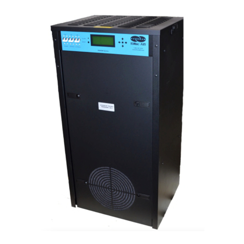
Seresco NE Series User manual

OPERATION AND
MAINTENANCE MANUAL
NE SERIES
DEHUMIDIFIERS
NE-008 to NE-016
NE-216toNE-232
Classic Indoor Model
serescodehumidifiers.com

B–TableofContent
OMM.B.S.BI.01
B‐
1
February
2020
TableofContent
ChapterC‐GeneralInformation C–1
OperatingSafety
C–1
ReferenceandAdditionalInformation
C–2
o
ContactUs
C–2
BasicInformation
C–3
oDehumidifierViewandOptions
C–3
o
DehumidifierExternalSystemsConnection
C–5
oDehumidifierOptionalArrangement
C–6
oAirConditioningOptions–OutdoorAirCondensersandFluidCoolers
C–6
o
EquipmentSpecificData
C–8
ChapterD‐LayoutandComponents D–1
DehumidifierMainComponents
D–1
ControlSystem
D–3
OutdoorAirCondensersandFluidCoolersLayoutandComponents
D–5
ChapterE‐SequenceofOperation E–1
SetPoints
E–1
Ventilation
SpaceHeating
E–1
E–1
AirConditioning,DehumidificationandPoolHeating
E–1
o
Compressor(s)
E–1
ChapterF‐InterfaceandCommunication F–1
TouchDisplayOperatorPanel
F–1
oAlarms F–2
RemoteCommunication
F–3
ChapterM‐BasicMaintenanceM‐1
MaintenanceandSafety
M–1
MaintenanceKeyPoints
M–1
RoutineMaintenanceProgram
M–2
SpecificComponentsMaintenance
M–3
ChapterW‐Warranty W–1

B–TableofContent
B‐
2
Thispageisleftblank

C–GeneralInformation
OMM.C.S.BI.01
C‐
1
February
2020
GeneralInformation
ThismanualprovidesbasicinformationabouttheapplicableSerescodehumidifieranditsoperation.
Importantinformationregardinginstallation,maintenance,andstartupaswellasadditionalandauxiliarysystems
anddevices(outdoorcondenser,communicationinterfaces,etc.)isnormallyprovidedwiththedehumidifierand
canalsobeobtainedfromthemanufacturer(seeContactUsbelow).
OperatingSafety(Warnings,Cautions,andNotes)
FORYOURSAFETY:READBEFOREPERFORMINGANYOPERATIONS,MAINTENANCEORSERVICETASKS!
Onlyqualifiedtechniciansshouldinstall,operate,maintainorservicemechanicalequipment
includingcurrentdehumidificationsystem.
Makesuretoreadthismanualbeforeperforminganytaskstofamiliarizeyourselfwiththe
equipmentaswellaswithanypotentialhazards.Alwaysexercisecaution!
Bewareofelectricalpowerandhighelectricalvoltage!
• Followpropersafetyprocedures–lockout,tagout,andotherrespectiveprocedures
• Failuretofollowsafetyprocedurescanresultinseriousinjuryordeath
Bewareofmovingpartsandhotsurfaces!
• Makesuretostopallmovingparts(fans,blowers,etc.)beforeaccessingtheequipment’s
internalspace
• Beawareofhotsurfaces(hotrefrigeration,spaceheatingpipes,coils,heaters,etc.)
Bewareofhighpressuresandchemicals!
• Dehumidifiers,equippedwithcompressors,containrefrigerantunderhighpressure;oilis
alsocontainedinthecompressorandrefrigerationcircuit(s)
• Somedehumidifiersmayalsocontainotherliquidssuchasglycolmixturesandpoolwater
Thefollowingwarnings,cautions,andnotesappearthroughoutthismanualandreferenceddocumentation
wheneverspecialcaremustbetakentoavoidpotentialhazardsthatcouldresultinequipmentmalfunctionor
damage,personalinjury,ordeath.
WARNING
Indicatesapotentiallyhazardous
situationwhichcouldresultin
seriousinjuryordeathifhandled
improperly.
CAUTION
Indicatesapotentiallyhazardous
situationwhichcouldresultin
moderateinjuryorequipment
damageifhandledimproperly.
Note
Indicatesasituationthatcould
resultinequipmentdamageor
improper/ineffectiveoperationif
handledimproperly.

C–GeneralInformation
C‐
2
ReferenceandAdditionalInformation
Forsafe,efficientandproblem‐freeoperation,itiscriticaltohandlethedehumidifier(aswellasrelatedsystems
andcomponents)properlyateachstep‐fromreceivingandstoragetoinstallationandstartup.Relevant
informationcanbefoundintherespectivedocuments(likeInstallationManual)providedwiththedehumidifier.
Thismanualandotherrelateddocumentscouldbeobtainedfromthemanufacturer(seeContactUsbelow).
ContactUs
Seresco
1071AgesDrive
Ottawa,ONK1G6L3
Canada
http://serescodehumidifiers.com
Forimmediateassistance:1‐833‐DAS‐POOL(327‐7665)
Start‐upRequests:Start‐ups@dehumidifiedairservices.com
MiscellaneousInquiries:[email protected]
PartsRequests: Parts@dehumidifiedairservices.com
Warranty: Warranty@dehumidifiedairservices.com
Attention:InstallationandServiceContractors
WARNING!
Anywork(installation,startup,service,maintenance,repair,etc.)onanymechanical
equipment(dehumidifier,outdoorcondenser,fluidcooler,etc.)mustbeperformedinaccordancewith
respectivemanufacturer’srecommendationsaswellassubmittaldocumentation,localCodesandRegulations,
andappropriatefieldpractices.Failuretodosocouldresultinpersonalinjury,equipmentdamageor
malfunction,andwillvoidequipmentwarranty.Onlyqualifiedandproperlytrainedindividualsshouldperform
tasksonthisequipment.
Attention:MaintenanceTeam
CAUTION.
Toensureequipmentlongevityandproperandefficientoperation,thedehumidifierandits
auxiliarysystemsanddevices(outdoorcondenser,fluidcooler,boilerpackage,etc.)shouldbemaintained
properlyandregularly.Failuretodosocouldnegativelyaffectpremisecomfortlevelsandpeople’shealth.It
couldalsoleadtoequipmentdamage,malfunction,prematuretearandwareandmayvoidequipmentwarranty.

C–GeneralInformation
OMM.C.S.BI.01
C‐
3
February
2020
BasicInformation
DehumidifierViewandOptions
StandardNE008–NE016dehumidifierscomeinhorizontal(Pic.C.1‐A)orvertical(Pic.C.1‐B)composition:
Pic.C.1‐A
HorizontalComposition
ReturnAir(RA)ductworkconnection‐
horizontal.
SupplyAir(SA)ductworkconnection
options–top,bottom,horizontalside
(leftorright).
OutdoorAir(OA)intakeductwork
connectionoptions–top,horizontalside
(leftorright).
PipingConnections
① CondensateDrain
② AC–Air‐Cooled(refrigeration)
③ AC–Water‐Cooled(water/glycol)
④ PoolHeatingWater
⑤ SpaceHeatingHotWater
Electricalconnection

C–GeneralInformation
C‐
4
DehumidifierOptions(applicabletoboth,verticalandhorizontal,configurations):
Indoor,single‐compressordehumidifiers,8to16toncoolingcapacity(apprx.)‐modelsNE008toNE016*.
oTwo‐compressordehumidifieroption(seeDehumidifierOptionalArrangementbelowfordetails):
16to32toncoolingcapacity(appx.)‐modelsNE216toNE232;
Airflowandductworkconnectionoptions(ReturnAir(RA),SupplyAir(SA)OutdoorAir(OA))*‐asshownon
Pic.C.1‐AandC.1–B.
OptionalPoolWaterHeating**.
OptionalSpaceHeating‐hotwatercoil,electricorgasheater***.
AirConditioning(AC)*–externalwatercooling,outdoorcondenserorfluidcooler.
*
Allavailableoptions(tonnage,ductworkconnections,ACoptionsetc.)areshown.Refertothesubmittal
andotherrelevantdocumentationforyourdehumidifier’soptions.
VerticalComposition
ReturnAir(RA)ductworkconnection‐
horizontal.
SupplyAir(SA)ductworkconnection
options–top,horizontalside(leftor
right).
OutdoorAir(OA)intake–top,horizontal
side(leftorright).
PipingConnections
① CondensateDrain
② AC–Air‐Cooled(refrigeration)
③ AC–Water‐Cooled(water/glycol)
④ PoolHeatingWater
⑤ SpaceHeatingHotWater
Electricalconnection
Pic.C.1‐B

C–GeneralInformation
OMM.C.S.BI.01
C‐
5
February
2020
**Thepoolwaterheatingoptionreliesoncompressor‐createdexcessheatandisusedasanadditional
heatingsource.Itdoesnoteliminatetheneedforamainpoolwaterheater.
***Forspecificdetailsonspaceheating(hotwater,gas,electric)option,refertothesubmittalandother
documentation:
Gas‐firedductheatercanbeprovidedforfieldinstallation(tobefittedinthesupplyairductwork).
Electricheaterorhotwatercoil,dependingoncapacity,model,size,etc.,canbeinstalledexternally(mountedonthe
topofSAopeningorfittedinthesupplyairductwork)orinternally.Refertoyourdehumidifier’ssubmittal
documentation.
DehumidifierExternalSystemsConnection
Pic.C.1–AandBshowprovisionsforexternalsystemsconnections,includingductwork,electricpowerand
controlwiresandvariouspipingconnections.
Exceptforthecondensate,allotherpipingsystemsareoptionalandmaynotbepresentineachdehumidifier.
AirConditioning(AC)Connection.Normally,thedehumidifierhasonlyoneACoption–air‐cooled(requiring
connectiontotheoutdooraircondenser)orwater‐cooled(requiringconnectiontothefluidcoolerorother
externalwater‐cooledsystemsuchasgeothermal,coolingtower,etc.).Therefore,onlyoneoftheseoptions
presentwiththeactualdehumidifier.
Gasline.Ifthedehumidifierisequippedwithagasheater(boiler,gasfurnaceetc.)forspaceheating
purposes,thegaslineconnectionistobebroughttothegasheaterdirectly.
Attention!EquipmentClearancesandDimensions!
CAUTION!
Forequipmentproperoperation,maintenanceandservice,respectiveclearancesshouldbe
maintained.Generally,30”clearancestotheequipmentmustbekeptforthemaintenanceandservicepurposes.
Forthespecificrequiredclearancesinformation,aswellasdehumidifieroveralldimensions,distancestopipe
connections,ductconnectionsetc.,refertothesubmittaldocumentation.
NOTE.
DehumidifierMUSTbeequippedwithaP‐trapatthecondensateconnectionforproperoperation!If
dehumidifierisrequested/providedfromthefactorywithoutP‐trap,oneMUSTbeinstalledonsitepriorto
dehumidifierbeingcommissioned.RefertothedehumidifierstickersandInstallationManualfordetails.
CAUTION!
Currentmanualshowsgeneral/defaultconnections’location.Fordetailsregardingspecific
dehumidifier’sconnections(actuallocation,pipingsizesandpositiondimensions,circuittypeandflowdirection
etc.),refertothedehumidifier’ssubmittaldocumentationaswellasdehumidifier’slabelsandstickers.
WARNING!
GasLine.Thegaslinemustbeinstalledinaccordancewithrespectivedevicedocumentation
(boiler,furnace,etc.)andlocalcodesandregulations.

C–GeneralInformation
C‐
6
DehumidifierOptionalArrangement
Two‐CompressorArrangement
StandardNEseriesdehumidifierhasonecompressor,
howevertwo‐compressorarrangementisavailablealso.Note,
thatalloptionsanddetails,providedabove,applytoboth,
standardandtwo‐compressorarrangement:
“Double‐Decker”dehumidifierisshownonPic.C.3.
Itiscomposedoftwoidenticaldehumidifiers,one
installedontopofanotherandcontrolledasasingle
dehumidifier(eachdeckisequippedwithone
compressor/refrigerationcircuit).
SingleandTwo‐CompressorArrangement–Dehumidifier
Model
Dehumidifiertypicalarrangement,totalcapacity,andnumberofcompressorsarereflectedinitsmodel(for
specificdehumidifiermodelrefertoitsMainLabel–seeSpecificDataInfobelow),asillustratedinexamples
below:
NE008–single‐decksingle‐compressordehumidifier.
Two‐compressorNEseriesdehumidifier:
NE216‐double‐decktwo‐compressordehumidifier(composedoftwoidenticaldehumidifiersNE008).
Mostoften,“Double‐Decker”comesastwohorizontaldehumidifiers,one“stacked”onthetopofanother,
howeveritcouldalsobecomposedoftwodehumidifiers(horizontalORvertical)installedsidebysideor
separately,stillbeingcontrolledasone.
AirConditioningOptions‐OutdoorAirCondensers(OACC)andFluidCoolers(OAFC).
BasicviewsofstandardairconditioningoptionsareshownonPic.C.4(below);standardcombinationsofthe
dehumidifierandrespectiveairconditioningoption(basedontheircapacities)areshowninTableC.1.
*TableC.1showsstandarddehumidifierand
condenser/coolercombination;dependingonnumberof
factors,dehumidifiermayhavedifferentcondenser/cooler
providedwithit‐refertothedehumidifier’ssubmittal
documentationformoredetails.
**Two‐compressordehumidifierwouldnormallyhave
paired‐uptwooutdoorcondensersofrespectivesize(oneper
compressor).
Forexample,NE216wouldhavedouble‐condenser,
composedoftwoNC‐Z‐1(seePic.C.4,Fig.1).
***Thepumppackageisoptional‐thefluidcoolermaybeprovidedwithoutit.
TableC.1.Dehumidifier‐ACCombination*
Dehumidifier–OutdoorCondenser**Fig.#
NE008NC‐Z‐11
NE010–NE016NC‐Z‐22
Dehumidifier–FluidCooler***Fig.#
NE008–NE012,
NE208–NE212
NG‐V‐113
NE014–NE016,
NE214‐NE224
NG‐V‐124
NE228–NE232NG‐V‐225
Pic.C.3

C–GeneralInformation
OMM.C.S.BI.01
C‐
7
February
2020
Attention!EquipmentClearances!
Properclearancesshouldbemaintainedforadequateairflowandheatrejection!Generally,upto36”sideand
96”topclearancesarerequired.Formoreinformationonclearancesaswellasequipmentdimensionsandother
details
,
refertothesubmittaldocumentation.
Pic.C.4

C–GeneralInformation
C‐
8
EquipmentSpecificData
Specificinformationforindividualdehumidifiersis
providedinthefollowingmethods:
MainLabel(Pic.C.5):themanufacturertagattached
tothefrontofthedehumidifierincludesthe
dehumidifier’smostcriticaldata:
Generaldataincluding:
oSerialnumber
oDehumidifiermodel(nomenclature)
oDesignroomconditions(airtemperature
andhumidity)
Operationaldata,including:
oRefrigeration(refrigeranttype,charge,
etc.)
oElectrical/airflow(dehumidifiervoltage,
CFM,etc.)
oOtherapplicabledata(poolheating,
space/auxiliaryheatingfeatures,etc.)
LabelsandStickers:attachedwhenapplicabletothe
exteriorandinteriorofthedehumidifiertoshow:
Externalsystemsconnectionslocation/direction
(pool/spaceheating,coolingcircuits,condensate)
Airfilterlocations,quantity,andsize.
AdditionalInfo(warning,cautionstickers,etc.)
WiringDiagrams:attachedtotheinteriorsideofthe
dehumidifier,depictdehumidifiercontrolandpower
wiring.
Remotelyinstalledcondenserorcoolerwouldhaveitsspecificinformationprovidedinsimilarmanner(labelsetc.).
Attention!GlycolCircuits.
Unlessotherwiseindicated,equipmentfluidcircuits(exceptforrefrigerationandpoolwatercircuits)suchasheat
recoveryloop,compressorglycolloop,boilerpackage,fluidcooleretc.,arenormallyfilled/tobefilledwith
water/glycolmixture;normally,rustinhibitor‐infusedfood‐gradepropyleneglycolisused.
GlycolmixtureconcentrationisnormallyshownonMainLabel–referasneeded.
Note:
Themainlabelshownaboveisjustanexample.
Pic.C.5

D–LayoutandComponents
OMM.D.S.BI.01
D‐
1
February
2020
LayoutandComponents
Thegenerallayoutandcomponentslocationisthesameforalldehumidifiersofcurrenttype,howeversomemay
vary,basedonthedehumidifier’sspecificoptions–refertosubmittaldocumentation.Pic.D.1A(vertical)andD.1B
(horizontal)belowshowall/mostavailableoptions,someofwhichmaynotbepresentonyourdehumidifier.
DehumidifierMainComponents
2
1
3
5
4
78
9
11
10
13
14
15
18
17
16
Pic.D.1A
11
13a
10a

D–LayoutandComponents
D‐
2
MainBlower(1)isinthemainblowercompartmentnexttotheMainElectricPanel(2)andCompressor
Compartment(3).Somemodelscouldbeequippedwithtwomainblowers.
MinOutdoorAir(OA)Opening(4)isoptionallyequippedwithamotorizeddamperandfilter(s).TheManual
OADamper(5)isusuallyusedtosetproperamountofoutdoorairintake.
Refrigerationcoils‐Evaporator(7)andReheat(internalcondenser)(8)‐arelocateddirectlydownstreamof
theMainFilterRack(9).
oEvaporatorBypassDamper(10)islocatednexttotheevaporatorcoil.Ithelpstocontrolcompressor
suctionpressurebyadjustingtheamountofair,bypassingtheevaporator.Mainmanualby‐pass
damper(10a)isusedtoadjustairflowacrossaircoils(evaporator,reheatandspaceheatingcoils).
Spaceheater(11)location,ifthedehumidifierisequippedwithone,mayvary:
oHotwatercoilisusuallylocateddirectlydownstreamofthereheatcoil;
oElectricheaterisusuallymounteddirectlyonthedehumidifier’ssupplyairductconnection.
oGasheater(ductheaterorboilerpackage),ifprovided,normallyisinstalledexternally(notshown).
2
1
3
5
4
78
9
11
10
1314
15
1817
16
13a
10a
Pic.D.1B

D–LayoutandComponents
OMM.D.S.BI.01
D‐
3
February
2020
Compressor(13),Receiver(14)andothercomponentsarelocatedwithintheCompressorCompartment(3).
oIfthedehumidifierhasthestandardpoolwaterheatingoption,thecompressorcircuitadditionally
includesthecoaxialpoolwaterheatexchanger(15)andrefrigerationpoolwaterheatingvalve.
oIfthedehumidifierhasthewater‐cooledairconditioningoption(equippedwithfluidcooleror
connectedtoexternalwater‐coolingsource),thecompressorcircuitalsoincludestheplateheat
exchanger(16).Somemodelsmayhaverefrigerationsuctionaccumulator(13a).
MainElectricPanelcontainsMainControlBoard(17),OperatorPanel(18)andotherelectricalcomponents.
ControlSystem
Thedehumidifiercontrolsystemiscomposedofsensors,spreadthroughoutthedehumidifier,MainControl
Board,OperatorPanelandotherelectriccomponents,locatedintheMainElectricPanel.
TemperatureSensors(Pic.D.2):
a) Temperaturesensors(thermistors)areusedtomonitor
varioustemperatures(air,water,compressor,etc.);
b) Combosensorisusedtomonitorairtemperatureand
humidity.
Compressoroperationismonitoredwithpressuresensors(Pic.D.3):
c) PressureTransducers(asmainoperationalcontrolandsafety)and
d) PressureSwitches(fast‐reactingbackupsafety).
SensorsandsafetiesapproximatelocationisshownonPic.D.4(seebelow).
RAComboSensor(21)measurestemperatureandhumidityofthepoolroomair(ReturnAir)enteringthe
dehumidifier.Itislocatedatthereturnairductworkconnectiontothedehumidifier.
OATemperatureSensor(22)measuresoutdoorairtemperature;it’slocatedattheOAfilterrack.
oAsanoption,thecombosensor(insteadofregularthermistor)canbeinstalledattheOAintaketo
measureboththetemperatureandhumidityoftheoutdoorair.
ET(EvapT)TemperatureSensor(23)measuresthetemperatureofairleavingevaporatorcoil.It’slocated
directlydownstreamoftheevaporator.
SAtemperaturesensor(24)measuresthetemperatureoftheairleavingthedehumidifier(suppliedtothe
premise).Itmustbelocateddownstreamofthespaceheater:
oInsomecases,wherethespaceheaterisexternaltodehumidifier,thesensorwillbeprovidedwith
thedehumidifiertobefield‐mountedintothesupplyairductworkdownstreamofthespaceheater.
Ifthedehumidifierisequippedwiththepoolheatingoption,thePoolWaterTemperaturesensors(PoolIn
(25)andPoolOut(26))measuretheenteringandleavingpoolwatertemperature.Thesensorsarelocated
directlyattherespectiveconnectionsofthecoaxialpoolwaterheatexchanger.
b
a
c
d
Pic.D.3
Pic.D.2

D–LayoutandComponents
D‐
4
oAsanoption,thepoolwaterheatexchangerpiping/manifoldmayhavewaterflowswitchalso.
Thecompressor’sdischargeline(highpressureside)isequippedwithTemperatureandPressuresensorsset‐
DischargeTemperatureSensor,HighPressureTransducerandHighPressureSwitch(27)‐toprotectthe
compressorandcontrolitsoperation.AsimilarfunctionisperformedbySuctionTemperatureSensor,Low
PressureTransducerandLowPressureSwitch(28)locatedatcompressor’ssuctionline(lowpressureside).
MainElectricPanel,apartfromdeviceslistedabove(controlboard,OP,etc.)alsocontainsVoltageMonitor;
someoptionalcontrolsensorsanddevicessuchasanairpressuredifferentialsensor,currentsensor(s).Itmay
alsobelocatedinmainelectricalpanelorinthedehumidifieringeneral.
Pic.D.4
21
23
24
22
26
27
25
28
27
28
21
22
23
24

D–LayoutandComponents
OMM.D.S.BI.01
D‐
5
February
2020
OutdoorAirCondensersandFluidCoolersLayoutandComponents
.
ThegenerallayoutofACoptions(air‐andwater‐cooled)isshownonPic.D.5belowwiththeoutdooraircondenser
NC‐Z‐1(left)andfluidcoolerNG‐V‐11(right)asanexample.Whilelayoutandmaincomponentsaresimilarforall
applicableACoptions,therearesomedeviations(numberoffans,coilsizes,composition,etc.).RefertoAC
OptionsBasicView(BasicInformationchapter)foradditionalinformation.
Cooling(AC)coil(s)(31)(whereheatfromrefrigerantintheoutdoorcondenserorglycolmixtureinfluidcooler
isrejectedtotheambientair)ismountedontometalframe/airboxupstream(before)thefan(32),thatpulls
theairthroughthecoiltoabsorbtheheat.
oCondenser/coolerpipingconnections(33)areidentifiedrespectively(IN–OUT,Hotgas–Liquidetc.);
Insomecases,fluidcoolerpipingconnection(s)maybelocatedwithinpumppackagebox
(37),iffluidcoolerisprovidedwithone.
Pipingconnectionlocationmayvary–refertoparticularcooler/condenserlabels,stickers,
submittalandotherdocumentation.
oDependingonthetype,sizeandinstallation,outdoorcondensersmaybeprovidedwithdifferentset
oflegs/supports(34),whicharerequiredassemblyon‐site–refertotheInstallationmanual.
oDependingonthesizeandcapacity,condenserorcoolermayhavemultiplefansorcoils.
Electricpowerisnormallytobebroughttodisconnect(35)(ifcooler/condenserisequippedwithsuch),which
feedsittotheelectricalbox(36),thatcontainscondenserorcoolerpowerandcontrolapparatuses.
oCondenser’spipingmanifold/connectionsnormallyareprotectedbytheelectricalpanelcover;
oDependingontypeoffluidcooler,locationofelectricalboxmayslightlydiffer;insomecases,
electricalboxmaybeincorporatedintopumppackage.
32
36
35
33
3437
31
NC‐Z‐1NG‐V‐11
Pic.D.5
31

D–LayoutandComponents
D‐
6
FluidCoolersPumpPackage.
FluidCoolers,ifequippedwithsuchoption,wouldhaveapumppackagebox.Pic.D.6belowshowsgenerallayout
ofpumppackages,usedforNG‐Vmodelfluidcoolers.Note,thatthepackagecouldbemountedontothefluid
coolerdirectly(standard)orprovidedseparately.
Pump(38)establishesglycolmixturecirculationthrough
thefluidcooleranddehumidifier;
Expansiontank(39)compensatesfortemperature‐
basedglycolvolumefluctuation;
Thepumppackageelectricalsub‐panel(40)containsthe
pumppackageelectricalpowerandcontrolapparatuses.
Thepumppackagemanifoldsareusuallyequippedwith
pressuregauges,automaticairventingvalve,draining
andothervalves.
Pic.D.6
38
40
39

E–SequenceofOperation
OMM.E.S.BI.01
E‐
1
February
2020
SequenceofOperation
Thedehumidifier’sventilationsystemestablishestherequiredairflowthroughthedehumidifier.Thecontrol
systemcomparesairtemperatureandhumiditytotheirdesiredvalues(setpoints)andproceedstodehumidify,
coolorheattherecirculatingair.
Ifthedehumidifierisequippedwiththepoolwaterheatingoption,thepoolwatertemperatureiscomparedtoits
setpointandpoolheatingisprovidedifrequired.
SetPoints
Thecontrolsystemisconstantlyadjustingunitoperationtoachieveandmaintainsaidparameterswithincouple
degrees/percentofthesetpoint.
Refertothedehumidifier’smainlabelforthedesignvalueofcontrolparameters,aswellasthefollowingnote.
Ventilation.
Themainblowerrunscontinuously,establishingrequiredairflowandpullingfreshoutdoorairontothepremise
throughtheminimumoutdoorairintake(OA1)damper.Themainblowerspeedispre‐setviaadjustablevariable
signal.
Dehumidifier,thoughusuallydoesnothaveitbuilt‐in,cancontroltheexternalminimumexhaustfan(EF1),to
directsportionofreturnairoutdoors.Likethemainblower,exhaustfanspeediscontrolledviaadjustable(pre‐set)
variablesignals:theexhaustfanspeedmayvarydependingonscheduledventilationmode(Occupied,Non‐
OccupiedandSpectator)orcallforEconomiserMode(aspartofAirConditioningorDehumidificationoperation).
Note.ExternallyinstalledExhaustFan(s)andOutdoorAirdamper(s)couldbealsocontrolledbythe
dehumidifiercontrolsystem.Thisappliestoboth,MinimumandPurge/Additional,fansanddampers.
SpaceHeating
Whenpremiseairtemperaturedropsbelowthesetpoint,thedehumidifiercontrolsystemissuesacallforSpace
HeatingModeandengagesspaceheater(electricheater,hotwatercoilwithvalve,gasboileretc.)bysendingspace
heatingsignal,respectivetospaceheatercontroltype‐on/off,variable(0‐10VDC),etc.
AirConditioning,DehumidificationandPoolHeating.
Compressor(s)
Wheneverthecompressoroperates,theevaporatorisalwaysdehumidifyingandcoolingthereturnair.Theheat
removedfromtheairattheevaporator,aswellastheheatfromthecompressor'saction,mustberejectedtoone
ofthreeheatsinks:room(premise)air,poolwater(ifapplicable)oroutdoors.Thecontrolsystemwilldirectthe
heattowhereitisneededbasedonroom(airandpoolwatertemperature)conditions:
Ifroomairisneededtobewarmedup–moreheatisdivertedtowardsreheatcoil;
Ifpoolwaterisneededtobewarmedup–moreheatisdivertedtowardspoolheatingcoaxialheatexchanger
(ifdehumidifierisequippedwiththisoption).
Note:
Toensurethedehumidifier’smosteconomicaloperation,werecommendmaintainingthefollowing
relationshipbetweenpoolwaterandroomairtemperatures:
RoomAirT=PoolWaterT+2˚F

E–SequenceofOperation
E‐
2
Restoftheheat(ifany)isdivertedtowardsoutdoors(outdoorcondenser,fluidcooler,etc.)
CompressorCircuitOperation
PipingschematicforcompressorcircuitisshownonPic.E.1.
Whenademandrequiresthecompressortooperate,thefollowingsequenceoccurs:
Oncebloweroperation,relatedsafetiesandtimersareconfirmedbythecontrolsystem,thepumpdown
solenoidvalveopensandoncepressurestabilizes,thecompressorstarts.
Basedonthepremiseairtemperature,therefrigerationreheatand/orACsolenoidvalveopens,allowing
refrigeranttoflowthroughtherespectivecondenser:
oifmoreheatisrequiredbytheroomair,thereheatsolenoidvalveopens(heatisrejectedtothe
premise);ifmorecoolingisrequiredbytheroomair,theACsolenoidvalveopens(heatisrejected
outdoors(viaoutdoorcondenserorplateheatexchanger).
o
Outdoorcondenserorfluidcoolerfanisengagedonlyifhotgasisdivertedoutdoorsandcompressor
pressureishigherthanpre‐setlevel(seeOutdoorCondenserandFluidCoolerOperationbelow).
Dehumidifiers,equippedwithpoolwaterheatingoption,alsoengagetherefrigerationpoolwaterheating
solenoidvalvetorejectheatintothepoolwater,basedonpoolwatertemperature.
Oncedemandforthecompressor’soperationisremoved(respectivecallissatisfied),thepumpdownsolenoid
valvecloses;oncethecompressorsuctionpressurereachesthepre‐setpressure,thecompressorstops.
OutdoorAirCondenserandFluidCoolerOperation.
Basedonthetypeoftheoutdoorcondenserorfluidcoolerfans’type(two‐speedfansorEC‐type/modulating
fans),respectivesignal(s)aresentbycontrolsystemtoengagesaidfan(s):fortwo‐speedfans‐on/offsignals
(switchingspeeds,basedoncompressorheadpressurelevel),forEC‐typefans‐variable0‐10VDCsignal
(proportionaltothecompressorheadpressurelevel).Refertothefans’typeandwiringdiagramif/whenneeded.
Ifthefluidcoolerisequippedwiththebuilt‐inpumppackage(toestablishcoolingfluidflowbetweendehumidifier
andthefluidcoolerortoserveasadditional/boosterpump),thesaidpumpisalsoengagedalongwithfluidcooler
fans–pumpwouldstayengagedwhilefansareengaged(regardlessofthefans’speed).
Pic.E.1

F–InterfaceandCommunication
OMM.F.S.ZZ.01
F‐
1
February
2020
InterfaceandCommunication
TouchDisplayOperatorPanel
TheTouchDisplayOperatorPanel(OP),shownonPic.F.1,isusedasamaininterfacebetweenthedehumidifier
andoperator.ThesameOPcanbelocatedinthedehumidifiermainelectricpanel(default;usedasalocalOP)or
installedremotelyfromthedehumidifier
NOTE:lengthofCAT5orCAT6cable,betweenremoteOPandthedehumidifierMUSTNOTexceed1000’!
TouchDisplayOPallowsto:
AccessTouchDisplayMenus
Viewdehumidifiercurrentoperational
statuses(TouchDisplayCommunication,
Alarms,dehumidifieroperationalcalls,etc.)
Viewcontrolledparameters’values(premise
airtemperature,humidityand,ifapplicable,
poolwatertemperature)andcurrentdate
andtime.
TouchDisplayMenus:
HomeOpens/returnstothehomepage
LogsAccesstodehumidifierlogsandlog‐relatedfeatures(Alarms
,
etc.)
UserAccesstousersettings(
S
etpoints)andcommands(
S
top/Restar
t
Dehumidifier,etc.)
AdvancedAccesstoadvancedsettingsandfeatures
HelpContextsensitivehelppresentinginformationrelatedtotheviewedpage
Mostcommon/basicmaintenancetasksperformedusingTouchDisplayOP
AdjustSetpoint–inUsermenu:presstheUserbutton,thenpresstheSetpointsbutton;selectdesired
parameter(roomairtemperatureetc.)andenterthedesiredvalue.PresstheEnterbuttontoconfirmthe
enteredvalue.
Stop/RestartDehumidifier––inUsermenu:presstheUserbutton,thenpresstheSystemRestartbutton;
oTostopandrestartdehumidifier,presstheSystemRestartbutton
oTorebootTouchDisplayOP,presstheRestartDisplaybutton
ReviewAlarmrecords––doneviatheLogsmenu:presstheLogsbutton,thenpresstheAlarmLogbutton.
Unlockdevice/dehumidifier,stoppedandcurrentlylockedoutonthealarm––doneviaLogsmenu:press
theLogsbutton,thenpresstheCurrentAlarmsbutton;presstheClearbuttonnexttotherespectivealarm
(thealarmthat’slockedoutthedeviceorentiredehumidifier).
FordetailedinformationonTouchDisplayOPrefertoDASVTouchDisplayManual,providedwiththedehumidifier
(orcontactfactorytoobtainacopy).
Pic.F.1
Other manuals for NE Series
2
This manual suits for next models
4
Table of contents
Other Seresco Dehumidifier manuals
