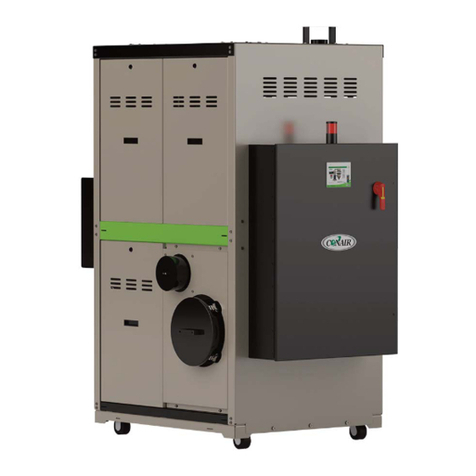
Seresco NE Series User manual

OPERATION AND
MAINTENANCE MANUAL
NE-002 to NE-016
NE-204 to NE-232
COMPACT Indoor Model
NE SERIES
DEHUMIDIFIERS
serescodehumidifiers.com

B–TableofContent
OMM.B.S.SL.01
B‐
1
February
2020
TableofContent
ChapterC‐GeneralInformation C–1
OperatingSafety
C–1
ReferenceandAdditionalInformation
C–2
o
ContactUs
C–2
BasicInformation
C–3
oDehumidifierViewandOptions
C–3
o
DehumidifierExternalSystemsConnection
C–4
oDehumidifierOptionalArrangement
C–5
oAirConditioningOptions–OutdoorAirCondensersandFluidCoolers
C–5
o
EquipmentSpecificData
C–8
ChapterD‐LayoutandComponents D–1
DehumidifierMainComponents
D–1
ControlSystem
D–2
OutdoorAirCondensersandFluidCoolersLayoutandComponents
D–4
ChapterE‐SequenceofOperation E–1
SetPoints
E–1
Ventilation
E–1
AirConditioning,DehumidificationandPoolHeating
E–1
o
Compressor(s)
E–1
SpaceHeating
E–3
ChapterF‐InterfaceandCommunication F–1
TouchDisplayOperatorPanel
F–1
oAlarms
F–2
RemoteCommunication
F–3
ChapterK–R3Module
K‐1
BasicInformation
K–1
oR3ModuleViewandOptions
K–1
R3ModuleExternalSysyemsConnection
K–2
R3ModuleLayoutandComponents
K–2
DehumidifierwithR3Module–SequenceofOperation
K–3
ChapterM‐BasicMaintenanceM–1
MaintenanceandSafety
M–1
MaintenanceKeyPoints
M–1
RoutineMaintenanceProgram
M–2
SpecificComponentsMaintenance
M–3
ChapterW‐Warranty W–1

B–TableofContent
B‐
2
Thispageisleftblank

C–GeneralInformation
OMM.C.S.SL.01
C‐
1
February
2020
GeneralInformation
ThismanualprovidesbasicinformationabouttheapplicableSerescodehumidifieranditsoperation.
Importantinformationregardinginstallation,maintenance,andstartupaswellasadditionalandauxiliarysystems
anddevices(outdoorcondenser,communicationinterfaces,etc.)isnormallyprovidedwiththedehumidifierand
canalsobeobtainedfromthemanufacturer(seeContactUsbelow).
OperatingSafety(Warnings,Cautions,andNotes)
FORYOURSAFETY:READBEFOREPERFORMINGANYOPERATIONS,MAINTENANCEORSERVICETASKS!
Onlyqualifiedtechniciansshouldinstall,operate,maintainorservicemechanicalequipment
includingcurrentdehumidificationsystem.
Makesuretoreadthismanualbeforeperforminganytaskstofamiliarizeyourselfwiththe
equipmentaswellaswithanypotentialhazards.Alwaysexercisecaution!
Bewareofelectricalpowerandhighelectricalvoltage!
• Followpropersafetyprocedures–lockout,tagout,andotherrespectiveprocedures
• Failuretofollowsafetyprocedurescanresultinseriousinjuryordeath
Bewareofmovingpartsandhotsurfaces!
• Makesuretostopallmovingparts(fans,blowers,etc.)beforeaccessingtheequipment’s
internalspace
• Beawareofhotsurfaces(hotrefrigeration,spaceheatingpipes,coils,heaters,etc.)
Bewareofhighpressuresandchemicals!
• Dehumidifiers,equippedwithcompressors,containrefrigerantunderhighpressure;oilis
alsocontainedinthecompressorandrefrigerationcircuit(s)
• Somedehumidifiersmayalsocontainotherliquidssuchasglycolmixturesandpoolwater
Thefollowingwarnings,cautions,andnotesappearthroughoutthismanualandreferenceddocumentation
wheneverspecialcaremustbetakentoavoidpotentialhazardsthatcouldresultinequipmentmalfunctionor
damage,personalinjury,ordeath.
WARNING
Indicatesapotentiallyhazardous
situationwhichcouldresultin
seriousinjuryordeathifhandled
improperly.
CAUTION
Indicatesapotentiallyhazardous
situationwhichcouldresultin
moderateinjuryorequipment
damageifhandledimproperly.
Note
Indicatesasituationthatcould
resultinequipmentdamageor
improper/ineffectiveoperationif
handledimproperly.

C–GeneralInformation
C‐
2
ReferenceandAdditionalInformation
Forsafe,efficientandproblem‐freeoperation,itiscriticaltohandlethedehumidifier(aswellasrelatedsystems
andcomponents)properlyateachstep‐fromreceivingandstoragetoinstallationandstartup.Relevant
informationcanbefoundintherespectivedocuments(likeInstallationManual)providedwiththedehumidifier.
Thismanualandotherrelateddocumentscouldbeobtainedfromthemanufacturer(seeContactUsbelow).
ContactUs
Seresco
1071AgesDrive
Ottawa,ONK1G6L3
Canada
http://serescodehumidifiers.com
Forimmediateassistance:1‐833‐DAS‐POOL(327‐7665)
Start‐upRequests:Start‐[email protected]
MiscellaneousInquiries:[email protected]
PartsRequests: Parts@dehumidifiedairservices.com
Warranty: Warranty@dehumidifiedairservices.com
Attention:InstallationandServiceContractors
WARNING!
Anywork(installation,startup,service,maintenance,repair,etc.)onanymechanical
equipment(dehumidifier,outdoorcondenser,fluidcooler,etc.)mustbeperformedinaccordancewith
respectivemanufacturer’srecommendationsaswellassubmittaldocumentation,localCodesandRegulations,
andappropriatefieldpractices.Failuretodosocouldresultinpersonalinjury,equipmentdamageor
malfunction,andwillvoidequipmentwarranty.Onlyqualifiedandproperlytrainedindividualsshouldperform
tasksonthisequipment.
Attention:MaintenanceTeam
CAUTION.
Toensureequipmentlongevityandproperandefficientoperation,thedehumidifierandits
auxiliarysystemsanddevices(outdoorcondenser,fluidcooler,boilerpackage,etc.)shouldbemaintained
properlyandregularly.Failuretodosocouldnegativelyaffectpremisecomfortlevelsandpeople’shealth.It
couldalsoleadtoequipmentdamage,malfunction,prematuretearandwareandmayvoidequipmentwarranty.

C–GeneralInformation
OMM.C.S.SL.01
C‐
3
February
2020
BasicInformation
DehumidifierViewandOptions
StandardNE002–NE003dehumidifier’sgeneralviewandoptions*areshownonPic.C.1.
DehumidifierOptions:
Indoor,single‐compressordehumidifiers,2to16toncoolingcapacity(apprx.)‐modelsNE002toNE016*.
oTwo‐compressordehumidifieroption(seeDehumidifierOptionalArrangementbelowfordetails):
4to32toncoolingcapacity(appx.)‐modelsNE204toNE232;
Airflowandductworkconnectionoptions*(Return,SupplyandOutdoorAir)‐seePic.C.1.
OptionalPoolWaterHeating**.
OptionalSpaceHeating‐hotwatercoil,electricorgasheater***.
AirConditioning(AC)*–externalwatercooling,outdoorcondenserorfluidcooler.
Pic.C.1
Options:
ReturnAir(RA)ductworkconnection‐
horizontal.
SupplyAir(SA)ductworkconnection
options–top,bottom,horizontal*.
OutdoorAir(OA)intake‐horizontal*.
PipingConnections
① CondensateDrain
② AC–Air‐Cooled(refrigeration)
③ AC–Water‐Cooled(water/glycol)
④ PoolHeatingWater
⑤ SpaceHeatingHotWater

C–GeneralInformation
C‐
4
*
Allavailableoptions(tonnage,ductworkconnections,ACoptionsetc.)areshown.Refertothesubmittal
andotherrelevantdocumentationforyourequipmentoptions,dimensionsetc.
**Thepoolwaterheatingoptionreliesoncompressor‐createdexcessheatandisusedasanadditional
heatingsource.Itdoesnoteliminatetheneedforamainpoolwaterheater.
***Forspecificdetailsonspaceheating(hotwater,gas,electric)option,refertothesubmittalandother
documentation:
Gas‐firedductheatercanbeincorporatedwiththedehumidifier(installedonthetopofit)forsomemodels(NE004to
NE007only);thisconfigurationlimitstheRAandSAoptionstoa“loop‐back”arrangement.Forothermodels,asimilar
gasheatercanbeprovidedforfieldinstallation(tobefittedinthesupplyairductwork).
Electricheater,dependingonvariousfactors(capacity,model,size,etc.),canbeinstalledexternally(mountedonthe
topofSAopening)orinternally.Refertoyourdehumidifier’ssubmittaldocumentation.
DehumidifierExternalSystemsConnection
Pic.C.1showsprovisionsforexternalsystemsconnections,includingductwork,electricpowerandcontrolwires
andvariouspipingconnections.
Exceptforthecondensate,allotherpipingsystemsareoptionalandmaynotbepresentineachdehumidifier.
AirConditioning(AC)Connection.Normally,thedehumidifierhasonlyoneACoption–air‐cooled(requiring
connectiontotheoutdooraircondenser)orwater‐cooled(requiringconnectiontothefluidcoolerorother
externalwater‐cooledsystemsuchasgeothermal,coolingtower,etc.).Therefore,onlyoneoftheseoptions
presentwiththeactualdehumidifier.
Gasline.Ifthedehumidifierisequippedwithagasheater(boiler,gasfurnaceetc.)forspaceheating
purposes,thegaslineconnectionistobebroughttothegasheaterdirectly.
NOTE.
DehumidifierMUSTbeequippedwithaP‐trapatthecondensateconnectionforproperoperation!If
dehumidifierisrequested/providedfromthefactorywithoutP‐trap,oneMUSTbeinstalledonsitepriorto
dehumidifierbeingcommissioned.RefertothedehumidifierstickersandInstallationManualfordetails.
CAUTION!
Currentmanualshowsgeneral/defaultconnections’location.Fordetailsregardingspecific
dehumidifier’sconnections(actuallocation,pipingsizesandpositiondimensions,circuittypeandflowdirection
etc.),refertothedehumidifier’ssubmittaldocumentationaswellasdehumidifier’slabelsandstickers.
WARNING!
GasLine.Thegaslinemustbeinstalledinaccordancewithrespectivedevicedocumentation
(boiler,furnace,etc.)andlocalcodesandregulations.
Attention!EquipmentClearancesandDimensions!
CAUTION!
Forequipmentproperoperation,maintenanceandservice,respectiveclearancesshouldbe
maintained.Generally,30”clearancestotheequipmentmustbekeptforthemaintenanceandservicepurposes.
Forthespecificrequiredclearancesinformation,aswellasdehumidifieroveralldimensions,distancestopipe
connections,ductconnectionsetc.,refertothesubmittaldocumentation.
Attention:R3Module
Note:
IfthedehumidifierisequippedwiththeR3Module(seeyourequipmentsubmittaldocumentation),refer
totheR3Modulechapterinthismanualforadditionalinformationaboutmoduleoptions,layout,andoperation.

C–GeneralInformation
OMM.C.S.SL.01
C‐
5
February
2020
DehumidifierOptionalArrangement.
Two‐CompressorArrangement
StandardNEseriesdehumidifierhasonecompressor,however
two‐compressorarrangementisavailablealso.Note,thatall
optionsanddetails,providedabove,applytoboth,standardand
two‐compressorarrangement:
“Double‐Decker”dehumidifierisshownonPic.C.3.Itis
composedoftwoidenticaldehumidifiers,oneinstalledon
topofanotherandcontrolledasasingledehumidifier
(eachdeckisequippedwithonecompressor/refrigeration
circuit).
SingleandTwo‐CompressorArrangement–DehumidifierModel
Dehumidifiertypicalarrangement,totalcapacity,andnumberofcompressorsarereflectedinitsmodel(for
specificdehumidifiermodelrefertoitsMainLabel–seeSpecificDataInfobelow),asillustratedinexamples
below:
NE002–single‐decksingle‐compressordehumidifier.
Two‐compressorNEseriesdehumidifier:
NE204‐double‐decktwo‐compressordehumidifier(composedoftwoidenticaldehumidifiersNE002).
Mostoften,“Double‐Decker”comesastwohorizontaldehumidifiers,one“stacked”onthetopofanother,
howeveritcouldalsobecomposedoftwodehumidifiers(horizontalORvertical)installedsidebysideor
separately,stillbeingcontrolledasone.
AirConditioningOptions‐OutdoorAirCondensers(OACC)andFluidCoolers(OAFC).
BasicviewsofstandardairconditioningoptionsareshownbelowonPic.C.4‐A(condensers,NCmodels)andPic.
C.4‐B(coolers,NGmodels);standardcombinationsofthedehumidifierandrespectiveairconditioningoption
(basedontheircapacities)areshowninTableC.1.
*TableC.1showsstandarddehumidifierand
condenser/coolercombination;dependingonnumberof
factors,dehumidifiermayhavedifferent
condenser/coolerprovidedwithit‐refertothe
dehumidifier’ssubmittaldocumentationformore
details.
**Two‐compressordehumidifierwouldnormally
havepaired‐uptwooutdoorcondensersofrespective
size(onepercompressor).
***Thepumppackageisoptional‐thefluidcooler
maybeprovidedwithoutit.
TableC.1.Dehumidifier‐ACCombination*
Dehumidifier–OutdoorCondenser**Fig.#
NE002–NE004NC‐B1
NE005–NE008NC‐Z‐12
NE010–NE016NC‐Z‐23
Dehumidifier–FluidCooler***Fig.#
NE002–NE003NG‐Z‐14
NE004–NE007,NE204–NE214NG‐V‐05
NE008–NE012,NE208–NE212NG‐V‐116
NE014–NE016,NE214‐NE224NG‐V‐127
NE228–NE232NG‐V‐228
Pic.C.3

C–GeneralInformation
C‐
6
Attention!EquipmentClearances!
Properclearancesshouldbemaintainedforadequateairflowandheatrejection!Generally,upto36”sideand
96”topclearancesarerequired.Formoreinformationonclearancesaswellasequipmentdimensionsandother
details
,
refertothesubmittaldocumentation.
Pic.C.4‐A

C–GeneralInformation
OMM.C.S.SL.01
C‐
7
February
2020
Pic.C.4‐B

C–GeneralInformation
C‐
8
EquipmentSpecificData
Specificinformationforindividualdehumidifiersis
providedinthefollowingmethods:
MainLabel(Pic.C.5):themanufacturertagattached
tothefrontofthedehumidifierincludesthe
dehumidifier’smostcriticaldata:
Generaldataincluding:
oSerialnumber
oDehumidifiermodel(nomenclature)
oDesignroomconditions(airtemperature
andhumidity)
Operationaldata,including:
oRefrigeration(refrigeranttype,charge,
etc.)
oElectrical/airflow(dehumidifiervoltage,
CFM,etc.)
oOtherapplicabledata(poolheating,
space/auxiliaryheatingfeatures,etc.)
LabelsandStickers:attachedwhenapplicabletothe
exteriorandinteriorofthedehumidifiertoshow:
Externalsystemsconnectionslocation/direction
(pool/spaceheating,coolingcircuits,condensate)
Airfilterlocations,quantity,andsize.
AdditionalInfo(warning,cautionstickers,etc.)
WiringDiagrams:attachedtotheinteriorsideofthe
dehumidifier,depictdehumidifiercontrolandpower
wiring.
Remotelyinstalledcondenserorcoolerwouldhaveitsspecificinformationprovidedinsimilarmanner(labelsetc.).
Attention!GlycolCircuits.
Unlessotherwiseindicated,equipmentfluidcircuits(exceptforrefrigerationandpoolwatercircuits)suchasheat
recoveryloop,compressorglycolloop,boilerpackage,fluidcooleretc.,arenormallyfilled/tobefilledwith
water/glycolmixture;normally,rustinhibitor‐infusedfood‐gradepropyleneglycolisused.
GlycolmixtureconcentrationisnormallyshownonMainLabel–referasneeded.
Note:
Themainlabelshownaboveisjustanexample.
Pic.C.5

D–LayoutandComponents
OMM.D.S.SL.01
D‐
1
June
2020
LayoutandComponents
Thegenerallayoutandcomponentslocationisthesameforalldehumidifiersofcurrenttype,howeversomemay
vary,basedonthedehumidifier’sspecificoptions–refertosubmittaldocumentation.Pic.D.1belowshows
all/mostavailableoptions,someofwhichmaynotbepresentonyourdehumidifier.
DehumidifierMainComponents
21
3
5
4
78
9
11
10
13
14
15
18
17
16
Pic.D.1
Attention:R3Module
Note:
IfthedehumidifierisequippedwiththeR3Module(seeyourequipmentsubmittaldocumentation),refer
totheR3Modulechapterinthismanualforadditionalinformationaboutmoduleoptions,layout,andoperation.

D–LayoutandComponents
D‐
2
MainBlower(1)isinthemainblowercompartmentnexttotheMainElectricPanel(2)andCompressor
Compartment(3).
MinOutdoorAir(OA)Opening(4)isoptionallyequippedwithamotorizeddamperandfilter(s).TheManual
OADamper(5)isusuallyusedtosetproperamountofoutdoorairintake.
Refrigerationcoils‐Evaporator(7)andReheat(internalcondenser)(8)‐arelocateddirectlydownstreamof
theMainFilterRack(9).
oEvaporatorBypassDamper(10)islocatednexttotheevaporatorcoil.Ithelpstocontrolcompressor
suctionpressurebyadjustingtheamountofair,bypassingtheevaporator.
Spaceheater(11)location,ifthedehumidifierisequippedwithone,mayvary:
oHotwatercoilisusuallylocateddirectlydownstreamofthereheatcoil;
oElectricheatermaybeinthesameplaceasthehotwatercoilormounteddirectlyonthe
dehumidifier’ssupplyairductconnection.
oGasheater(ductheaterorboilerpackage)normallyisinstalledexternally,howeversomemodels
couldhaveductgasheatermountedonthetopofthedehumidifier.
Compressor(13),Receiver(14)andothercomponentsarelocatedwithintheCompressorCompartment(3).
oIfthedehumidifierhasthestandardpoolwaterheatingoption,thecompressorcircuitincludesthe
coaxialpoolwaterheatexchanger(15)andrefrigerationpoolvalve.
oIfthedehumidifierhasthewater‐cooledairconditioningoption(equippedwithfluidcooleror
connectedtoexternalwater‐coolingsource),thecompressorcircuitalsoincludestheplateheat
exchanger(16)).
MainElectricPanelcontainsMainControlBoard(17),OperatorPanel(18)andotherelectricalcomponents.
ControlSystem
Thedehumidifiercontrolsystemiscomposedofsensors,spreadthroughoutthedehumidifier,MainControl
Board,OperatorPanelandotherelectriccomponents,locatedintheMainElectricPanel.
TemperatureSensors(Pic.D.2):
a) Temperaturesensors(thermistors)areusedtomonitor
varioustemperatures(air,water,compressor,etc.);
b) Combosensorisusedtomonitorairtemperatureand
humidity.
Compressoroperationismonitoredwithpressuresensors(Pic.D.3):
c) PressureTransducers(asmainoperationalcontrolandsafety)and
d) PressureSwitches(fast‐reactingbackupsafety).
SensorsandsafetiesapproximatelocationisshownonPic.D.4.
b
a
c
d
Pic.D.3
Pic.D.2

D–LayoutandComponents
OMM.D.S.SL.01
D‐
3
June
2020
RAComboSensor(21)measurestemperatureandhumidityofthepoolroomair(ReturnAir)enteringthe
dehumidifier.Itislocatedatthemainfilterrack.
OATemperatureSensor(22)measuresoutdoorairtemperature;it’slocatedattheOAfilterrack.
oAsanoption,thecombosensor(insteadofregularthermistor)canbeinstalledattheOAintaketo
measureboththetemperatureandhumidityoftheoutdoorair.
ET(EvapT)TemperatureSensor(23)measuresthetemperatureofairleavingevaporatorcoil.It’slocated
directlydownstreamoftheevaporator.
SAtemperaturesensor(24)measuresthetemperatureoftheairleavingthedehumidifier(suppliedtothe
premise).Itmustbelocateddownstreamofthespaceheater:
oInsomecases,wherethespaceheaterisexternaltodehumidifier,thesensorwillbeprovidedwith
thedehumidifiertobefield‐mountedintothesupplyairductworkdownstreamofthespaceheater.
Ifthedehumidifierisequippedwiththepoolheatingoption,thePoolWaterTemperaturesensors(PoolIn
(25)andPoolOut(26))measuretheenteringandleavingpoolwatertemperature.Thesensorsarelocated
directlyattherespectiveconnectionsofthecoaxialpoolwaterheatexchanger.
oAsanoption,thepoolwaterheatexchangerpiping/manifoldmayhavewaterflowswitchalso.
Thecompressor’sdischargeline(highpressureside)isequippedwithTemperatureandPressuresensorsset‐
DischargeTemperatureSensor,HighPressureTransducerandHighPressureSwitch(27)‐toprotectthe
compressorandcontrolitsoperation.AsimilarfunctionisperformedbySuctionTemperature,LowPressure
TransducerandSwitch(28)locatedatcompressor’ssuctionline(lowpressureside).
MainElectricPanel,apartfromdeviceslistedabove(controlboard,OP,etc.)alsocontainsVoltageMonitor;
someoptionalcontrolsensorsanddevicessuchasanairpressuredifferentialsensor,currentsensor(s).Itmay
alsobelocatedinmainelectricalpanelorinthedehumidifieringeneral.
Pic.D.4
21
23
24
22
26
27
25
28

D–LayoutandComponents
D‐
4
OutdoorAirCondensersandFluidCoolersLayoutandComponents
.
ThegenerallayoutofACoptions(air‐andwater‐cooled)isshownonPic.D.5belowwiththeoutdooraircondenser
NC‐B‐1(left)andfluidcoolerNG‐V‐0(right)asanexample.Whilelayoutandmaincomponentsaresimilarforall
applicableACoptions,therearesomedeviations(numberoffans,coilsizes,composition,etc.).RefertoAC
Options(BasicInformationchapter)foradditionalinformation.
Cooling(AC)coil(31)(whereheatfromrefrigerantintheoutdoorcondenserorglycolmixtureinfluidcooleris
rejectedtotheambientair)ismountedontometalframe/airboxupstream(before)thefan(32),thatpulls
theairthroughthecoiltoabsorbtheheat.
oCondenser/coolerpipingconnections(33)areidentifiedrespectively(IN–OUT,Hotgas–Liquidetc.);
Insomecases,fluidcoolerpipingconnection(s)maybelocatedwithinpumppackagebox
(37),iffluidcoolerisprovidedwithone.
Pipingconnectionlocationmayvary–refertoparticularcooler/condenserlabels,stickers,
submittalandotherdocumentation.
oDependingonthetype,sizeandinstallation,outdoorcondensersmaybeprovidedwithdifferentset
oflegs/supports(34),whicharerequiredassemblyon‐site–refertotheInstallationmanual.
oDependingonthesizeandcapacity,condenserorcoolermayhavemultiplefansorcoils.
Electricpowerisnormallytobebroughttodisconnect(35)(ifcooler/condenserisequippedwithsuch),which
feedsittotheelectricalbox(36),thatcontainscondenserorcoolerpowerandcontrolapparatuses.
oDependingontypeoffluidcooler,locationofelectricalboxmayslightlydiffer.
32
36
35
33
34
37
31
NC‐B‐1
NG‐V‐0
Pic.D.5

D–LayoutandComponents
OMM.D.S.SL.01
D‐
5
June
2020
FluidCoolersPumpPackage
FluidCoolers,ifequippedwithsuchoption,wouldhaveapumppackagebox.Pic.D.6belowshowsgenerallayout
ofpumppackages,usedforNG‐Z(left)andNG‐V(right)fluidcoolers.NotethatthepackageusedwithNG‐V
coolerscouldbemountedontothefluidcoolerdirectly(standard)orprovidedseparately.
Pump(38)establishesglycolmixturecirculationthroughthefluidcooleranddehumidifier;
Expansiontank(39)compensatesfortemperature‐basedglycolvolumefluctuation;
Thepumppackageelectricalsub‐panel(40)containsthepumppackageelectricalpowerandcontrol
apparatuses.
oDuetothecompactdesignofthefluidcoolerNG‐Z,theelectricalsub‐panelincludespowerand
controlapparatusesforthefluidcoolerandthepumppackageitself.
Thepumppackagemanifoldsareusuallyequippedwithpressuregauges,automaticairventingvalve,draining
andothervalves.
40383938
4039
Pic.D.6
NG‐ZNG‐V

D–LayoutandComponents
D‐
6
Thispageisleftblank

E–SequenceofOperation
OMM.E.S.SL.02
E‐
1
February
2020
SequenceofOperation
Thedehumidifier’sventilationsystemestablishestherequiredairflowthroughthedehumidifier.Thecontrol
systemcomparesairtemperatureandhumiditytotheirdesiredvalues(setpoints)andproceedstodehumidify,
coolorheattherecirculatingair.
Ifthedehumidifierisequippedwiththepoolwaterheatingoption,thepoolwatertemperatureiscomparedtoits
setpointandpoolheatingisprovidedifrequired.
SetPoints
Thecontrolsystemisconstantlyadjustingunitoperationtoachieveandmaintainsaidparameterswithincouple
degrees/percentofthesetpoint.
Refertothedehumidifier’smainlabelforthedesignvalueofcontrolparameters,aswellasthefollowingnote.
Ventilation.
Themainblowerrunscontinuously,establishingrequiredairflowandpullingfreshoutdoorairontothepremise
throughtheminimumoutdoorairintake(OA1)damper.Themainblowerspeedispre‐setviaadjustablevariable
signal.
Dehumidifier,thoughusuallydoesnothaveitbuilt‐in,cancontroltheexternalminimumexhaustfan(EF1),to
directaportionofreturnairoutdoors.Likethemainblower,exhaustfanspeediscontrolledviaadjustable(pre‐
set)variablesignals:theexhaustfanspeedmayvarydependingonscheduledventilationmode(Occupied,Non‐
OccupiedandSpectator)orcallforEconomiserMode(aspartofAirConditioningand/orDehumidification
operation).
Note.ExternallyinstalledExhaustFan(s)andOutdoorAirdamper(s)couldbealsocontrolledbythe
dehumidifiercontrolsystem.Thisappliestoboth,MinimumandPurge/Additional,fansanddampers
AirConditioning,DehumidificationandPoolHeating.
Compressor(s)
Wheneverthecompressoroperates,theevaporatorisalwaysdehumidifyingandcoolingthereturnair.Theheat
removedfromtheairattheevaporator,aswellastheheatfromthecompressor'saction,mustberejectedtoone
ofthreeheatsinks:room(premise)air,poolwater(ifapplicable)oroutdoors.Thecontrolsystemwilldirectthe
heattowhereitisneededbasedonroom(airandpoolwatertemperature)conditions:
Ifroomairisneededtobewarmedup–moreheatisdivertedtowardsreheatcoil;
Ifpoolwaterisneededtobewarmedup–moreheatisdivertedtowardspoolheatingcoaxialheatexchanger
(ifdehumidifierisequippedwiththisoption).
Restoftheheat(ifany)isdivertedtowardsoutdoors(outdoorcondenser,fluidcooler,etc.)
Note:
Toensurethedehumidifier’smosteconomicaloperation,werecommendmaintainingthefollowing
relationshipbetweenpoolwaterandroomairtemperatures:
RoomAirT=PoolWaterT+2˚F
Attention:R3Module
Note:
IfthedehumidifierisequippedwiththeR3Module(seeyourequipmentsubmittaldocumentation),refer
totheR3Modulechapterinthismanualforadditionalinformationaboutmoduleoptions,layout,andoperation.

E–SequenceofOperation
E‐
2
CompressorCircuitOperation
PipingschematicforcompressorcircuitisshownonPic.E.1.
Whenademandrequiresthecompressortooperate,thefollowingsequenceoccurs:
‐Oncebloweroperation,relatedsafetiesandtimersareconfirmedbythecontrolsystem,thepumpdown
solenoidvalveopensandoncepressurestabilizes,thecompressorstarts.
‐Reheatvalvedivertsportionofhotgasintothereheatcoil.Remainderofthehotgasgoesintooutdoor
condenser(orwater‐cooledheatexchanger,coupledwithfluidcoolerorexternalfluidcoolingsystem)and(if
applicable)poolwaterheatexchanger.
o
Dehumidifierwithpoolheatingoption:poolvalvedivertsportionofhotgasintopoolwaterheat
exchanger,basedonpoolwaterheatingdemand.
o
Outdoorcondenser/fluidcoolerfanisengagedonlyifhotgasisdivertedoutdoors/towater‐cooled
heatexchangerandcompressorpressureishigherthanpre‐setlevel(seeOutdoorCondenserandFluid
CoolerOperationbelow).
‐Oncedemandforthecompressor’soperationisremoved(respectivecallissatisfied),thepumpdownsolenoid
valvecloses;oncethecompressorsuctionpressurereachesthepre‐setpressure,thecompressorstops.
OutdoorCondenserandFluidCoolerOperation.
Basedonthetypeoftheoutdoorcondenserorfluidcoolerfans’type(two‐speedfansorEC‐type/modulating
fans),respectivesignal(s)aresentbycontrolsystemtoengagesaidfan(s):fortwo‐speedfans‐on/offsignals
(switchingspeeds,basedoncompressorheadpressurelevel),forEC‐typefans‐variable0‐10VDCsignal
(proportionaltothecompressorheadpressurelevel).Refertothefans’typeandwiringdiagramif/whenneeded.
Ifthefluidcoolerisequippedwiththebuilt‐inpumppackage(toestablishcoolingfluidflowbetweendehumidifier
andthefluidcoolerortoserveasadditional/boosterpump),thesaidpumpisalsoengagedalongwithfluidcooler
fans–pumpwouldstayengagedwhilefansareengaged(regardlessofthefans’speed).
Pic.E.1

E–SequenceofOperation
OMM.E.S.SL.02
E‐
3
February
2020
SpaceHeating
Whenpremiseairtemperaturedropsbelowthesetpoint,thedehumidifiercontrolsystemissuesacallforSpace
HeatingModeandengagesspaceheater(electricheater,hotwatercoilwithvalveetc.)bysendingspaceheating
signal,respectivetospaceheatercontroltype‐on/off,variable(0‐10VDC),etc.
Other manuals for NE Series
2
This manual suits for next models
17
Table of contents
Other Seresco Dehumidifier manuals

