Sesamo ARIETE User manual
INSTALLATION MANUAL
Antipanic Breakaway System
ARIETE

2
Installation Manual
ARIETE
Installation Manual ARIETE
3
Contents
Operation typology of the ARIETE antipanic breakaway system ..........................page 4
Preparation of the sliding leaf ................................................................................page 9
Preparation of the semi-fixed leaf ..........................................................................page 11
Phases of assembly and installation of the ARIETE system..................................page 12
Leaf positioning ......................................................................................................page 21
Magnetic Reed Installation......................................................................................page 23
Installation of the safety photocell (Optional – partial Ariete) ................................page 24
Testing of the system..............................................................................................page 26
We would like to thank you for choosing this product.
In order to obtain the best performance of the ARIETE sys-
tem, the Sesamo Company recommends that you read and
carefully follow the installation and use instructions provided
in this manual. The installation of the ARIETE system must
be performed only by professionally qualified personnel to
whom this manual is directed. Any errors during the installa-
tion phase may be the source of danger for people or things.
The packaging materials (wood, plastic, cardboard, etc.)
should not be discarded in the environment or left within
reach of children since they are potentially dangerous. Each
individual phase of the installation must be performed in con-
formity with the current regulations and, in any case, accord-
ing to the dictates of general good practices. Ensure, before
beginning the installation, that the product is integral and has
not been damaged during transport or as a result of improp-
er storage. Before installing the product ensure that each
architectonic and structural element of the entrance (beam
fastening surfaces, fixtures, guide, etc.) is suitable and suffi-
ciently sturdy to be automated. Conduct a careful analysis of
the risks and make appropriate modifications to eliminate the
areas of dragging, crushing, shearing and of danger in gen-
eral.The manufacturer of the ARIETE system is not liable for
any unobservance of general good practices or specific reg-
ulations in the construction of the fixture to be motorised and
of any failures of the same. All of the protective safety
devices of the automatic door (photocells, active sensors,
etc.) must be installed in conformity with the regulations and
directives in force, the risk analysis, the system typology, the
use, the traffic, and the forces and inertias in play.Always pay
particular attention to the zones were there may occur:
crushing, shearing, dragging and any other danger in gener-
al, placing appropriate signs if necessary. Use only original
spare parts in maintenance or repair operations. Do not
tamper with or alter for any reason the internal parts of the
ARIETE system.The manufacturer declines any responsibil-
ity in the event that the internal parts of the ARIETE system
are tampered with or used improperly. The installer of the
ARIETE system is obligated to provide the person in charge
of the automatic door with the user’s manual and all the infor-
mation necessary for a correct use. Pay particular attention
to the messages in this manual marked by the danger sign.
These may either be warnings aimed at preventing potential
damage to the equipment or specific signals of potential dan-
ger for the safety of the installer or other people involved.
This system has been designed for the breakaway of auto-
matic sliding doors in case of emergency. Any other use will
be considered contrary to the use foreseen by the manufac-
turer who, consequently, cannot be held liable.

4
ARIETE
Installation Manual
Operation typology of the ARIETE antipanic breakaway system
TOTAL ARIETE (T.A.)
Breakaway system for sliding and semi-
fixed door leaves (Fig. 1 and 2).
Fig. 1
I
E
I
E
I
E
I
E
Example: 2 sliding leaves
SA L.I.
SA
SA
SA
V
Fig. 2
IInterior
EExterior
SA Breakaway direction
LI Crossbeam inspection side
VEmergency passageway
ARIETE
Ariete is available in different models according to the characteristics of the leaf to which it must be coupled and on the
basis of the surface finish.
In particular, it is necessary to choose the type of system using the following stock table once the width and weight of the
leaf are known:
Ariete is available untreated or with silver-coloured
anodising treatment.
This manual does not make any distinction between
the different models available since the assembly
follows the same scheme.
ATTENTION:If the width of the leaf is greater
than 1200 mm, it is necessary to install a third
carriage to the leaf (element not provided in the KIT,
to be ordered separately).
Leaf width ARIETE
[mm]
PF04.01 - PF04.02 PF04.08 - PF04.09
(min.=570) Leaf weight with Ariete (12 Kg) included
600 From 0 to 135kg
700 From 0 to 115kg
800 From 0 to 115kg
900 From 0 to 90kg From 50 to 125kg
1000 From 0 to 80kg From 50 to 115kg
1100 From 0 to 70kg From 50 to 110kg
1200 From 50 to 100kg
1300 From 50 to 90kg
1400 From 50 to 80kg

Installation Manual ARIETE
5
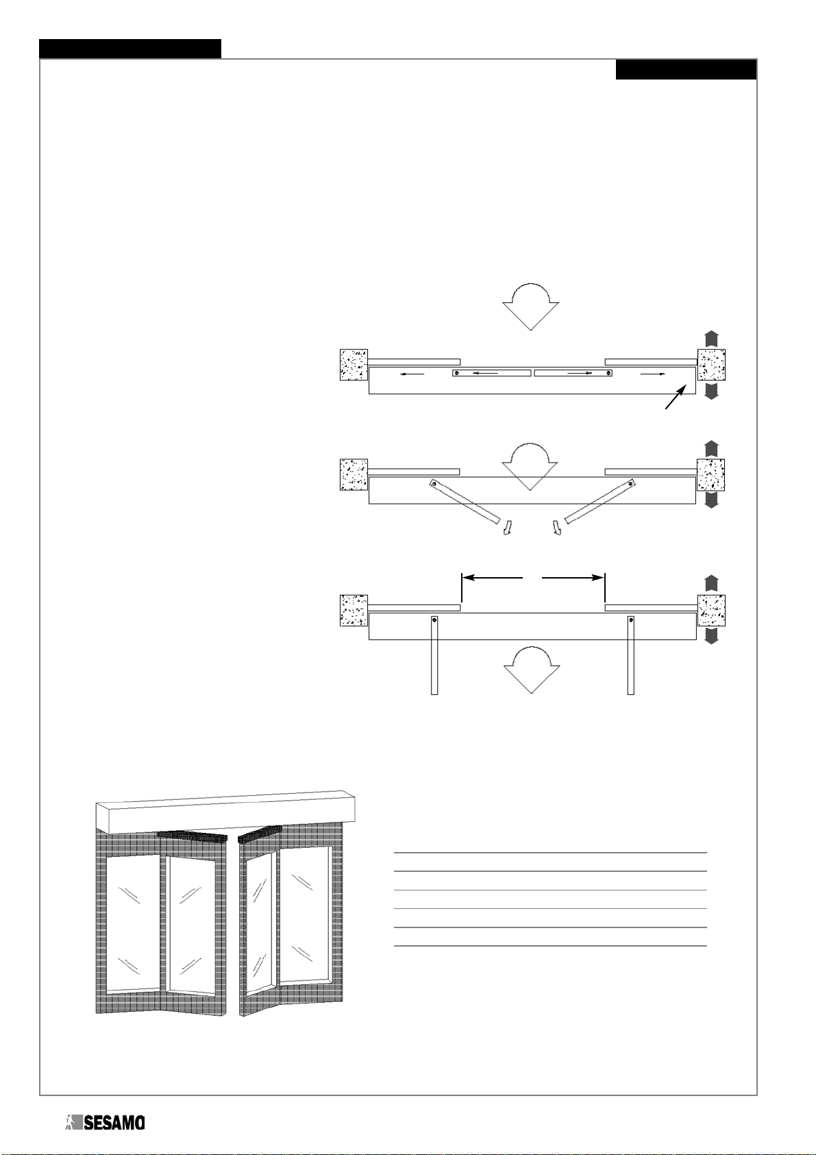
TOTAL ARIETE
Standard Doors (Fig.3a)SESAMO Magnum Doors (Fig.3b)
HCo Under-cover height
HAF Fixed leaf height
HAS Sliding leaf height HCo + HC –HAr - HT
HAr ARIETE system height 78,5mm
HC Under-cover – under-carriage distance
HT Under-sliding leaf – floor distance 13mm
IInterior
EExterior
For HC refer to the manuals of the automatism installed.
Fig. 3a Fig. 3b
ATTENTION: Keep the
minimum distance of 8mm
between the sash and the lower
ARIETE section shown in the
figure.
EIEI
6
ARIETE
Installation Manual
PARTIAL ARIETE
Breakaway system for sliding
leaves only (Fig. 4 and 5).
IInterior
EExterior
SA Breakaway direction
LI Crossbeam inspection side
VEmergency passageway
Fig. 5
Fig. 4
Example: 2 sliding leaves
I
E
I
E
I
E
SA
L.I.
SA
SA
V

Installation Manual ARIETE
7
PARTIAL ARIETE
Standard Doors (Fig.6a)SESAMO Magnum Doors (Fig.6b)
HCo Under-cover height HAF
HAF Fixed leaf height HCo
HAS Sliding leaf height HCo + HC –HAr - HT
HAr ARIETE system height 78,5mm
HC Under-cover – under-carriage distance
HT Under-sliding leaf – floor distance 13mm
IInterior
EExterior
For the value of HC refer to the manual of the automatism installed.
Fig. 6a Fig. 6b
EIEI

8
ARIETE
Installation Manual
TOTAL ARIETE
(sliding leaves and semi-fixed leaves)
A known LUP known T known
T4A-2SC+2Qmc 2LUP+2SC+2Qmc -
LUP 2A-2SC - T-2SC-2Qmc
2
A-LUP+2SC T+2SC-2Qmc
24
FORMULAS for crossbeams with the ARIETE system
SC End overlap
LUP Width of useful passageway
ALeaf width
XCasing thickness
YLeaf thickness
Qmc Machine quotient in rear
LUP SCSC
A
T
A
Standard Doors (Fig.13a)Magnum Door (Fig.13b, 13c)
Qmc
X
Y
10
Fig. 12
Fig. 13a Fig. 13b Fig. 13c
Partial ARIETE
Refer to the formulas provided in the manual of the automatism used without any modification.
Total ARIETE
Qmc
Qmc = 86 mm Qmc = 100 mm
Qmc
ARIETE
9
Installation Manual
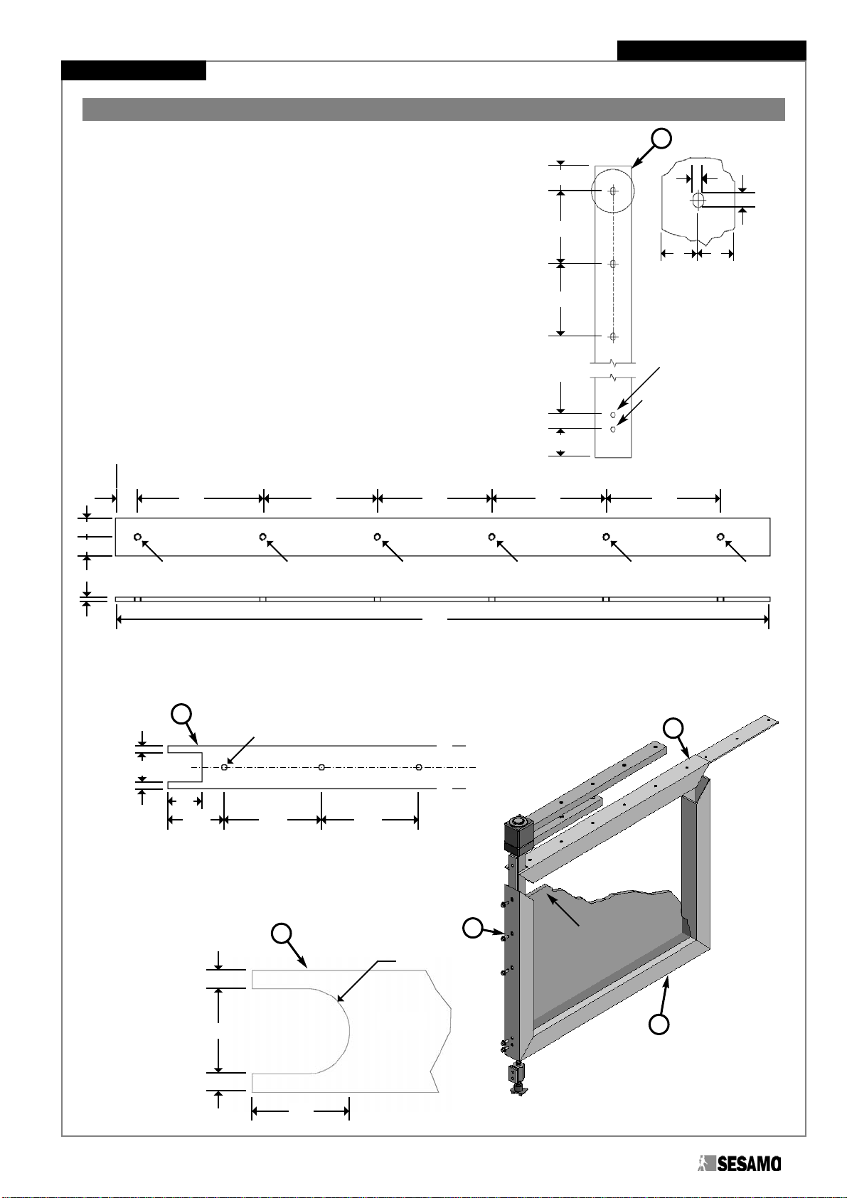
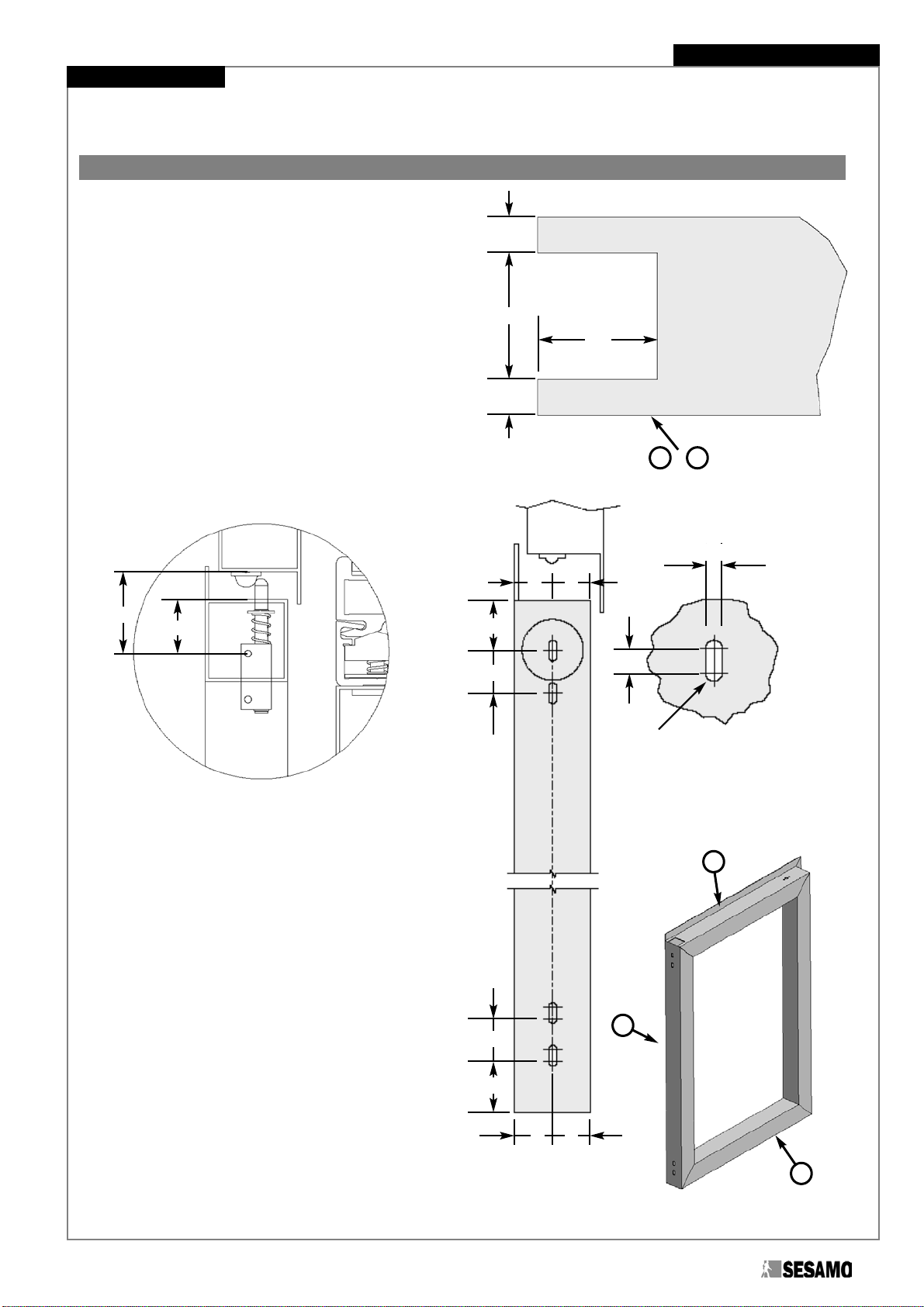
Preparation of the sliding leaf
Standard Doors
In the case of Standard doors:
- Perform the 3 slots and the 2 holes with diameter of 6.5mm on
the upright Athat will host the vertical rod of the ARIETE
system (Fig.14).
- Prepare a steel plate of minimum thickness 4mm with length
equal to L = Leaf Width – (2x50), and a width suitable to
guarantee a solid and secure fastening between the lower
ARIETE section and the upper crosspiece B.Drill and thread
the plate following the indications along the entire length (Fig.
15).
- Drill the upper crosspiece Bof the leaf following the indications
along the entire length of the crosspiece (Fig 16).
- Work the lower crosspiece Caccording to the scheme indicated
by the side of the strickle arm (Fig. 17).
- Insert the steel plate into the correct seat of the upper
crosspiece B(Fig. 18).
ATTENTION:Verify that the threaded holes of the plate are concentric with those present on the upper crosspiece B
and that they are spaced exactly according to the proportions of the drawing.
ATTENTION:Use appropriately sized doors suitable to
support the forces and the stresses caused by the breakaway of the
leaves, in the case of emergency, by means of the ARIETE system.
Fig. 14
Fig. 15
Fig. 16
Fig. 17
Fig. 18
35
7
5
= =
100
100
20
38
Ø 6.5
Ø 6.5
4
28
40
Ø 6.5
66.5 115 115
20 115
M6X1
M6X1
M6X1
M6X1
M6X1
M6X1
115 115
L
115 115
=
=
=
=
Strickle Zone
=
=
35
40
Ø 35
A
BB
A
C
C

10
ARIETE
Installation Manual
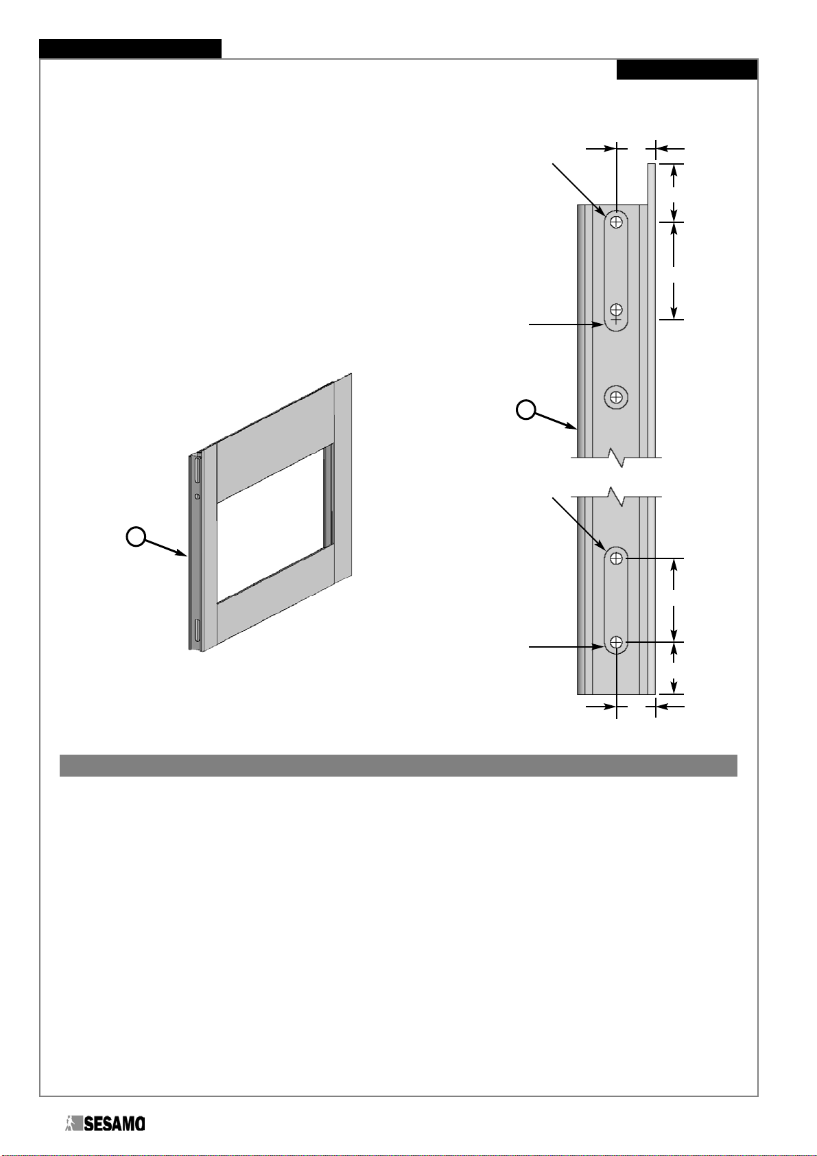
SESAMO Magnum Doors
In the case of SESAMO Magnum doors, position the lower
section/leaf fastening plaques into the correct seat on the
upper crosspiece and, as in the working of the Magnum
sections, perform:
- The 3 slots and the 2 holes of diameter 6.5mm on the
upright Athat will host the vertical rod of the ARIETE
system (Fig. 19).
- An opening on the upper crosspiece B(Fig. 20).
7
20
20
30
90
90
20
38
R=3.5
Ø 6.5
Ø 6.5
10
Fig. 19
40
=
=
28
Fig. 20
Fig. 21
A
B
B
A
Installation Manual ARIETE
11
Preparation of the semi-fixed leaf
Standard Doors
In the case of Standard doors:
- Perform an opening on the upper crosspiece Band on
the lower crosspiece C(Fig. 22).
- Calculate the centre of the top slot (quota X) so that the
distance between this and the supporting plane of the
coupling (see Fig. 57, 58) is equal to 50 mm (Fig. 23).
- perform the slots on the upright Aopposite of that which
will host the hinge (Fig. 24).
ATTENTION:Use
appropriately sized doors
suitable to support the forces
and the stresses caused by the
breakaway of the leaves, in the
case of emergency, by means
of the ARIETE system
=
X
24
28
30
=
= =
5.5
R=2.75
8
X
50
32
30
=
=
=
Fig. 22
Fig. 23
Fig. 24
Fig. 25
A
B
C
B C
HINGE SIDE
12
ARIETE
Installation Manual
SESAMO Magnum Doors
In the case of SESAMO Magnum Doors perform:
- the slots on the upright Aopposite of that which will host the
hinge (Fig. 26).
Fig. 27
Phases of assembly and installation of the ARIETE system
Materials provided in the ARIETE Kit
- Upper worked section
- Lower worked section
- Worked guide section
- Vertical steel bar with rotation pin
- Lower steel bar
- Upper steel bar with pin seat
- Accessories box + screws + optionals
ATTENTION:Before installing the ARIETE system ensure that:
- All the architectonic and structural parts that support the automatism (beam fastening surfaces, etc.) and all the
elements that make up the installed automatism (carriages, guides, etc.) are suitable to support the forces and the
stresses caused by the breakaway of the leaves, in the case of emergency, by means of the ARIETE system.
20
30
50
20
30
27
Ø 12
Ø 12
Ø 12
Ø 12
Fig. 26
HINGE SIDE
A
A
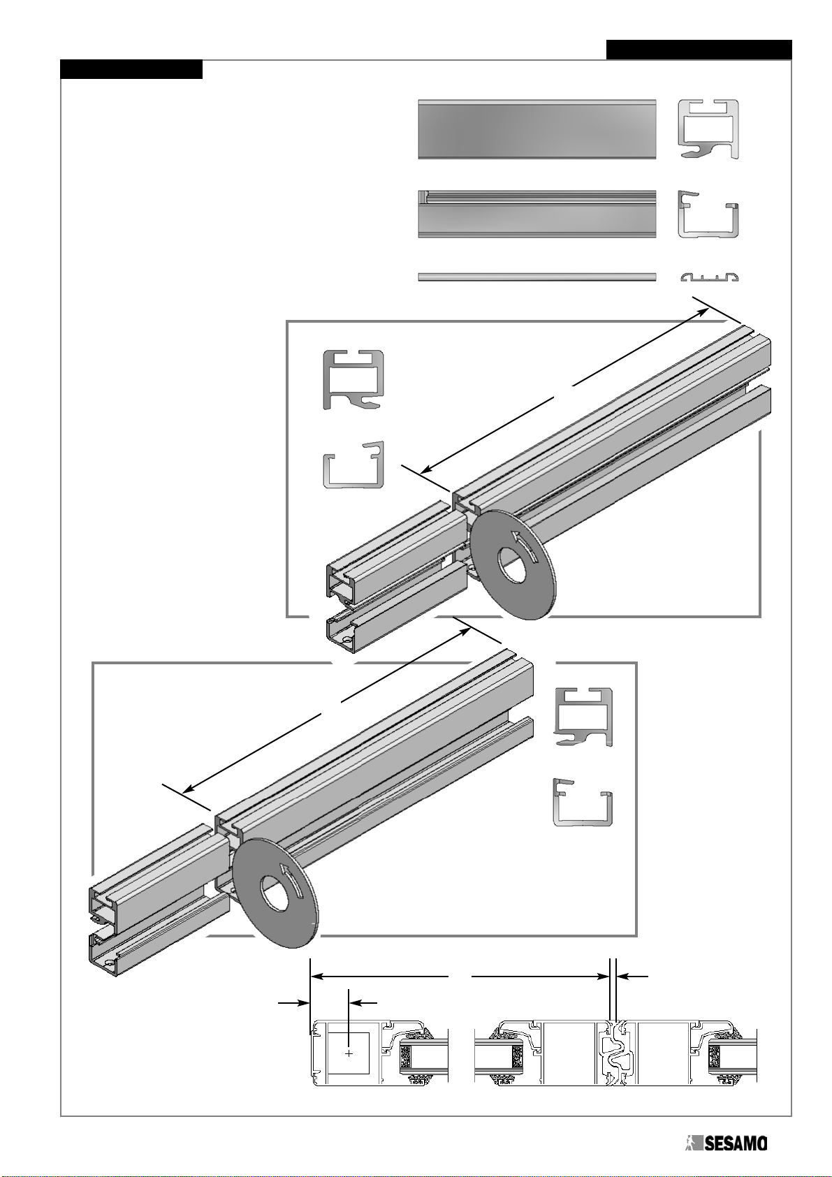
Cutting of the sections
Identify the correct case (Case A or Case B)
referring to the various operational typologies
listed below (Fig. 32-40).
ATTENTION:Be very
careful to cut the correct side.
Cut the upper section and the
lower section at the correct length
using the indicated formula (Fig.
29-31).
L = A + G - 60
A= Leaf width (aluminium only)
G= seal dimension (Magnum
Sections: G = 4 mm)
Installation Manual ARIETE
13
Fig. 28
Case A
Case B
L
L
Fig. 29
Fig. 30
Fig. 31
23.5
A G

14
ARIETE
Installation Manual
PARTIAL ARIETE
TOTAL ARIETE
1 Leaf opens LX P.A. 1 Leaf opens RX P.A.
2 Leaves P.A.
I
E
I
E
I
E
B A
B A
Fig. 32 Fig. 33
Fig. 36
1 Leaf opens RX T.A. 1 Leaf opens LX T.A.
2 Leaves T.A.
I
E
I
E
I
E
B A
B A
Fig. 38 Fig. 39
Fig. 40

Installation Manual ARIETE
15
Cut the floor guide
section at the correct
length using the
indicated formula (Fig.
41a-c).
Fig. 41a
Fig. 41b
Fig. 41c
L
A
79
HA HL
Lg
5
5
30
leaf in open
position
Lg = Leaf width + 30
13
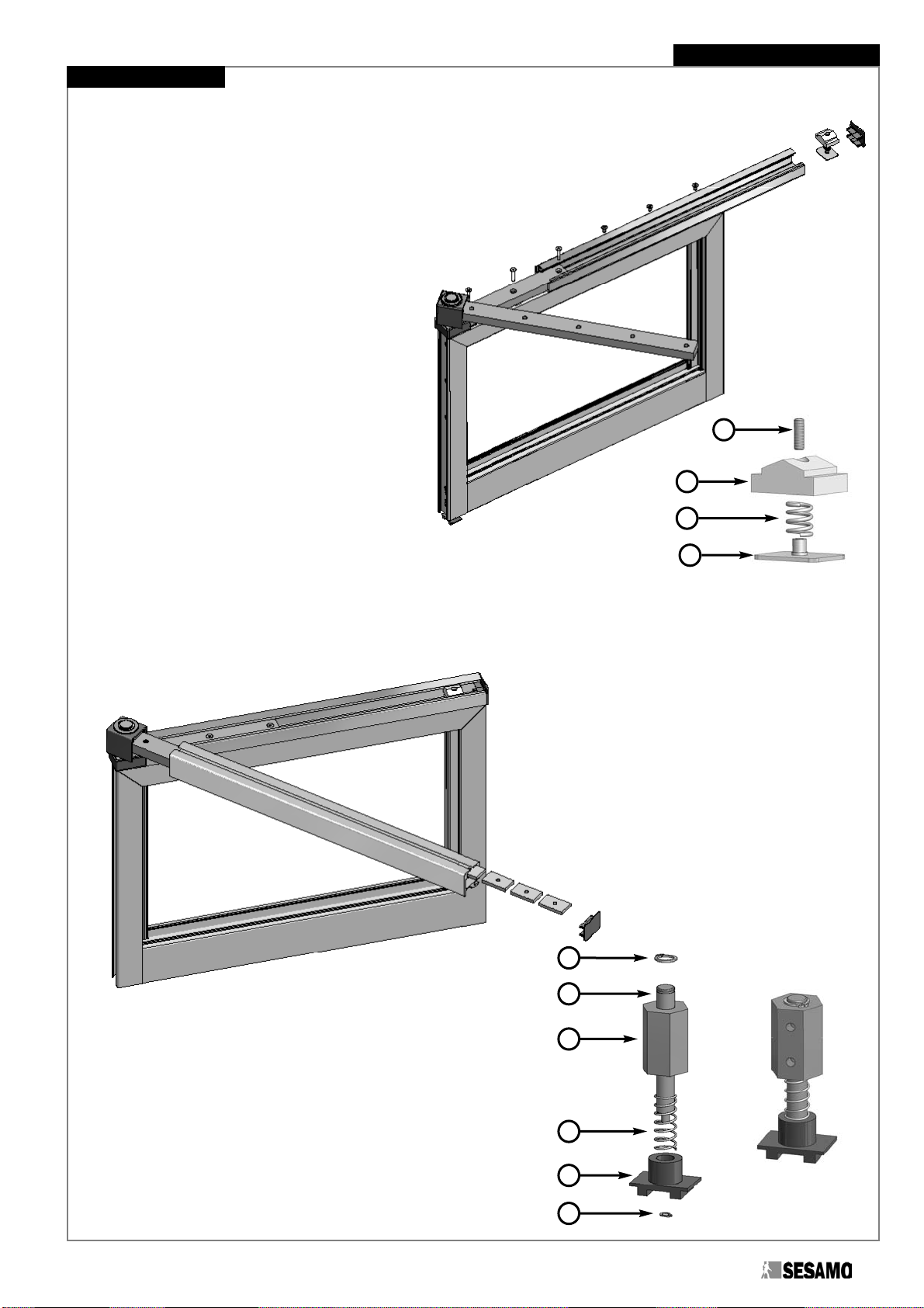
Assembly of the rotation pin complex (Fig. 42a)
Insert in sequence onto the vertical
rod (1) :
- lower blade (2) (with the two locking
holes turned downwards) blocked
with two elastic pegs 6x20 (3)
inserted into the hole on the vertical
rod
- the upper blade (5), respecting the
direction indicated in Fig. 42b
- 5 M8x16 conical point dowels (4)
(screw them in so that the head is
2mm under the surface of the the
upper blade (5))
- the cube cover (6)
- turned strickle fastening washer (7)
- the strickle fastening seeger Ø24 (8)
Fig. 42a
1
3
6
7
2
84
5
Fig. 42b
12.5
5
2
16
ARIETE
Installation Manual
Positioning of the (strickle) rotation pin complex onto the sliding leaf
SESAMO Magnum Sections
Thread the (strickle) rotation pin complex onto the vertical
section of the sliding leaf, inserting the lower blade cover into
the correct position (the 2 conical couplings of the cover
inserted into the 2 holes of the lower blade), fix the vertical
rod of the strickle by screwing the 3 M6x8 TE flanged screws
(Fig 43). Do not over-tighten the screws since the final
fastening will occur after having positioned the lower section
(Fig. 47 page 17 ).
Standard sections
Thread the (strickle) rotation pin complex onto the vertical
section of the sliding leaf, inserting the lower blade cover into
the correct position (the 2 conical couplings of the cover
inserted into the 2 holes of the lower blade), fix the vertical
rod of the strickle by screwing the 3 M6x8 TE flanged screws
(Fig. 44). Do not over-tighten the screws since the final
fastening will occur after having positioned the lower section (Fig. 47 page 17 ).
In the case of Standard sections place between
the internal upright and the strickle rotation pin
one or more steel or aluminium blades so that the
centre of the rotation axis is exactly at 23.5mm
from the external upright (Fig 45, 46).
A= 23,5 – 12,5 – S
A= distance between the internal
upright and the rotation pin
S= thickness of the upright section
ATTENTION:Be very careful about
the direction of breakthrough. Fig. 43
Fig. 44
Fig. 45
Fig. 46
ATTENTION:Be very careful about the
direction of breakthrough.
MIN.20
MAX
.25
A
==
25
25
Ø 7
100
100
250
SA12.5
23.5
Installation Manual ARIETE
17
Positioning and fastening of the lower and upper sections
Lower section (Fig. 47a):
Put the lower blade of the strickle onto the lower section until stopping it against
the lower blade cover.
The fastening occurs by screwing 3 M6x30 TS CEI screws in the
zone with the strickle and the M6x12 TS CEI screws in the
free zone suitably spaced (at least 1 screw every 2
holes). If necessary, loosen the fastening screws of
the strickle to the upright previously positioned (Fig.
43 and 44).
In the case of SESAMO Magnum doors the screws
are screwed to the lower section/leaf fastening
plaques.
In the case of SESAMO Standard doors the
screws are screwed to the lower section/leaf steel
plate (Fig. 15 page 9).
Insert inside the lower section the release force
regulator assembled as follows (Fig. 4b):
- put the spring (1) onto the release force regulator
plate (2)
- position the release force regulator slide (3)
- insert a M5x16 conical point dowel (4)
Tighten well the M6x8 TE flanged screws used for the vertical
fastening of the strickle onto the upright (Fig 43 and 44)
Position the section cap with the reference arrow turned upwards.
Upper section (Fig. 48):
- Put the upper blade of the strickle onto the upper
section and stop it against the cube cover
cube (Fig. 48).
- Screw in the 5 M8x16 conical point dowels
previously inserted into the holes of the upper
blade.
- Insert into the appropriate seat of the upper section
the 4 automatism adapter plaques. If 3 carriages
are mounted, 2 more plaques have to be
inserted.
- Position the section cap with the
reference arrow
turned upwards.
Assembly of the guide shoe complex (Fig. 49a, 49b)
Put the guide shoe pin (Fig 49a, part 1) inside the hole on the
guide shoe (Fig 49a, part 2)
Insert in sequence onto the guide shoe pin:
- the guide shoe spring (Fig. 49a, part 3)
- the guide shoe body (Fig. 49a, part 4)
- the 11mm seeger into the appropriate seat (Fig. 49a, part 5)
- the self-blocking 5mm seeger for the fastening of the guide
shoe onto the pin (Fig. 49a, part 6)
Fig. 47a
Fig. 48
Fig. 49a Fig. 49b
5
1
4
3
2
6
Fig. 47b
1
4
3
2

Fig. 52
18
ARIETE
Installation Manual
Positioning of the guide shoe complex onto the sliding leaf
Insert the guide shoe complex into the vertical section of the sliding leaf and
fasten it with two M6x8 TE flanged screws (Fig. 50).
In the case of Standard sections place between the internal upright and the
guide shoe rotation pin one or more steel or aluminium blades (Fig. 51) so that
the centre of the rotation axis is exactly at 23.5mm from the external upright
(see Fig. 45, 46), the fastening screws must be chosen according to the
thickness of the spacer so as to not obstruct the running of the guide shoe
pin (Fig 52).
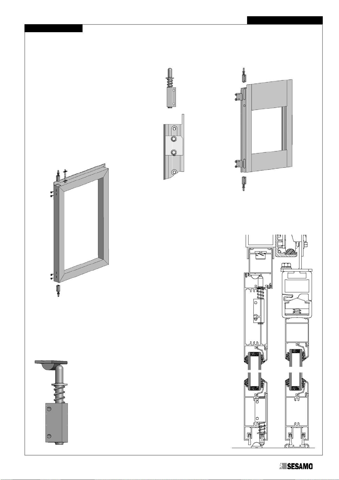
Assembly of the semi-fixed leaf release device complex (Fig. 53a, b)
Mount the 8mm seeger (Fig. 53a, part 2) into the appropriate seat on the semi-fixed release
device pin (Fig. 53a, part 1).
Insert in sequence onto the semi-fixed release device pin:
- one or more 8mm washers to obtain the desired preloading (Fig. 53a, part 3)
- the semi-fixed spring (Fig. 53a, part 4)
- the semi-fixed release device body (Fig. 53a, part 5)
Finish everything with the seeger 8mm (Fig. 53a, part 6)
in the appropriate seat.
ATTENTION:It is possible to vary the retention
force of the semi-fixed leaf exclusively by adding one
or more washers (Fig 53a, part 3).
Fig. 50
Fig. 51
A
40
Ø 7
20
= =
MIN.20 MAX.25
5
1
4
3
2
6
Fig. 53a
Fig. 53b
Installation Manual ARIETE
19
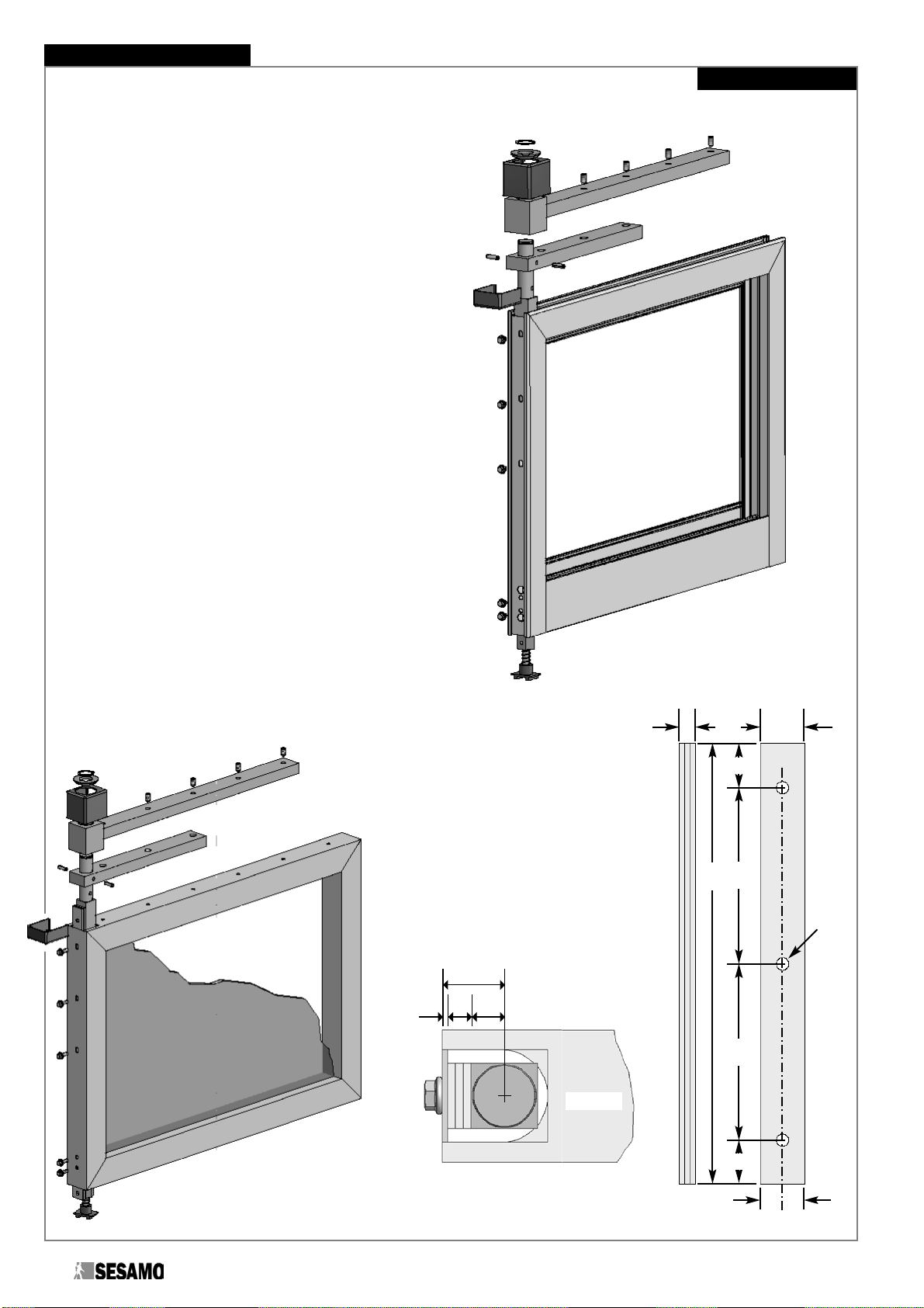
Positioning of the semi-fixed release complex onto the semi-fixed leaf (TOTAL ARIETE)
SESAMO Magnum Sections (Fig 54a)
In the case of the SESAMO Magnum
sections insert the 2 assembled semi-fixed
release groups into the vertical section of the
semi-fixed leaf, fix them with the M5x16 TE
flanged screws and appropriate plaques
(positioned as in Fig. 54b) inserted into the
external seat of the upright. Do not over-tighten
the fastening screws so as to allow for a later
adjustment of the height (Fig. 57).
Standard sections (Fig 55)
In the case of Standard sections, insert
the two assembled semi-fixed release
groups into the vertical section of the
semi-fixed leaf and fasten them with the
M5x16 TE flanged screws. Do not over-tighten
the fastening screws so as to allow for a later
adjustment of the height (Fig. 57).
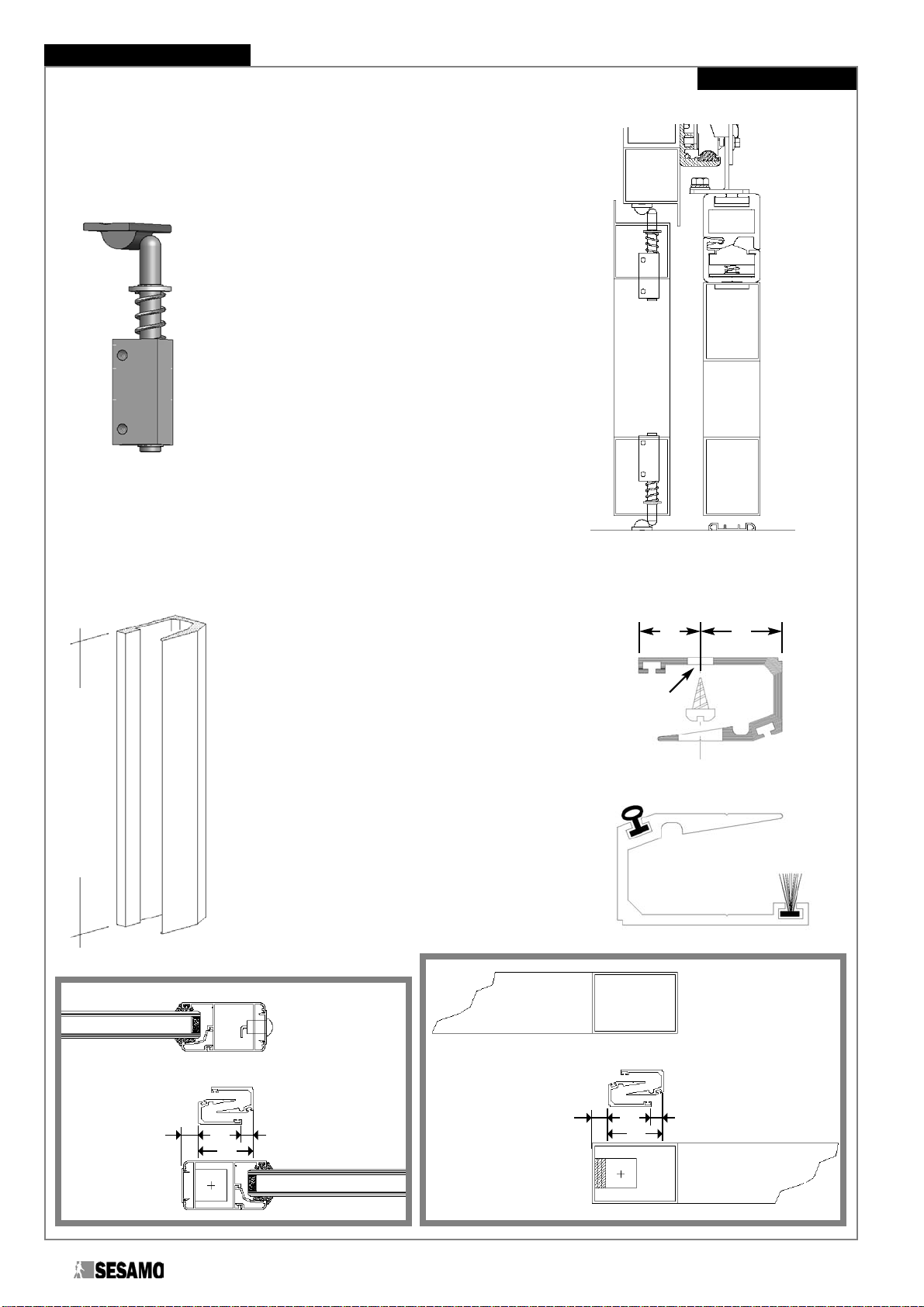
Fastening of the semi-fixed release coupling (TOTAL ARIETE)
SESAMO Magnum Sections
In the case of SESAMO Magnum sections fasten the semi-fixed release coupling to
the floor, in a central position with respect to the semi-fixed leaf, with 2 6mm plugs and
2 AF 4x40 screws and work on the slots to move the coupling into contact with the
hemispherical zone of the release device (Fig 56, 57).
Insert the upper semi-fixed release coupling into the seat of the
“glassholder” of the rabbet frame before assembling it and
fastening it to the door with 2 AF 4.2x9.5 screws (Fig. 56).
Adjust the height of the release device so that its hemispherical
end touches the coupling at the middle of the curved ramp (Fig.
57).Tighten well the M5x16 TE flanged screws.
ATTENTION:Pay particular attention to the adjustment of
the device since any error may compromise the correct operation.
Do not use the slots to vary the preloading of the spring, for this
purpose action can be taken exclusively at the moment of the
device assembly (Fig.53a, b).
Fig. 54b
Fig. 54a
Fig. 57
Fig. 56
Fig. 55
HINGE SIDE
20
ARIETE
Installation Manual
Standard sections
In the case of Standard sections fasten the semi-fixed release coupling to
the floor, in a central position with respect to the semi-fixed leaf, with 2
6mm plugs and 2 AF 4x40 screws.
Fasten the upper semi-fixed release coupling to
the door with 2 AF 4.2x9.5 screws in a central
position with respect to the semi-fixed leaf and
work on the slots to move the coupling into contact
with the hemispherical zone of the trigger device
(Fig. 57, 58).
Adjust the height of the release device so that its
hemispherical end touches the coupling at the
middle of the curved ramp (Fig. 57).Tighten well
the M5x16 TE flanged screws.
ATTENTION:Pay particular attention to the
adjustment of the device since any error may
compromise the correct operation. Do not use the
slots to vary the preloading of the spring, for this
purpose action can be taken exclusively at the
moment of the device assembly (Fig.53a, b).
Fig. 57
Fig. 58
Fastening of the sealing sections (TOTAL ARIETE)
- Cut the sealing section to the length HL = H
leaf – 78.5 mm (Fig. 41a, 59a).
- Drill the fixed and sliding leaves following the
scheme in Fig. 60a, b.Provide for at least 1
screw every 400mm, excluding the strickle zone
of the sliding leaf.
- Drill the sealing sections in the fastening zones
according to the scheme in Fig. 59b.The
position and the interaxis of the holes must
correspond with those performed on the sealing
sections.
- Fasten the sealing sections onto the fixed and
sliding leaves using appropriately sized self-
threading screws.
- Insert the brush and the rubber profile into the
appropriate channels of the sealing section
(Fig. 59c)
Fig. 59a
Fig. 60a Fig. 60b
Fig. 59b
Fig. 59c
15 20
Ø 5
H sealing section = HL
13 35
45 10 13 35
45 10
fixed leaf
sliding leaf
fixed leaf
sliding leaf
This manual suits for next models
4
Table of contents
Popular Safety Equipment manuals by other brands

Lanex
Lanex PB-20 instruction manual

SKYLOTEC
SKYLOTEC ANCHOR ROPES Instructions for use

Besto
Besto Buoyancy Aid 50N Instructions for use

TEUFELBERGER
TEUFELBERGER NODUS Manufacturer's information and instructions for use

Troy Lee Designs
Troy Lee Designs Tbone Product owners manual

Innova
Innova Xtirpa Instruction and safety manual

bolle SAFETY
bolle SAFETY B810 quick start guide

SHENZHEN FANHAI SANJIANG ELECTRONICS
SHENZHEN FANHAI SANJIANG ELECTRONICS A9060T instruction manual

Hiltron security
Hiltron security POWER8E Installation and use manual

Salewa
Salewa MTN SPIKE user manual

Hatco
Hatco B-950P installation guide

Sitec
Sitec TX MATIC operating manual


