Setcom MS-900MAX User manual

INSTALLATION AND USERS GUIDE
3019 Alvin DeVane Blvd.
Ste. 560
Austin, TX 78741
Phone: (650) 965-8020
CORPORATION
®
TECH SUPPORT: 650-965-8020 ext. 703
The Setcom MS-900SPW4 is a Wireless Radio Interface for use
with up to 7 LibMAX Series Wireless Headsets:
Radio Transmit Headsets:
CSB-900MAX (standard)
CSB-902MAX (vented)
Intercom-Only Headsets:
CSB-901MAX (standard)
CSB-905MAX (vented)
The MS-900MAX is typically connected to a single mobile radio
through use of the proper radio cable.
Adding an RRC-950 Radio Routing Controller and a
25-0108 connecting cable will allow operation with two radios. One
radio cable will be required for each radio. The RRC-950 has a
toggle switch that allows for switching TX, RX, and PTT functions
between the two radios (RX can be either summed or switched).
The MS-900MAX can be powered from 12 to 24 VDC, supplied by
a vehicle power system. The unit has an internal 1 Amp ATO-type
fuse, but it is recommended that the vehicle power source also be
fused (at least 1 A).
The system starts up as soon as power is applied.
No “pairing” is required to use headsets with the base unit, the
headsets only need to be on the same channel as the base unit
(displayed in the CHANNEL indicator).
Changing channels is accomplished by pressing the CHANNEL
SELECT button.
Typically no adjustments are required, but if transmit or receive
audio levels to and from the radio need adjustment, see page 3.
Questions or technical issues? Please call:
Page 1 of 5
5/30/16 SBH MS-900MAX_UserGuide_REV_X2.pdf
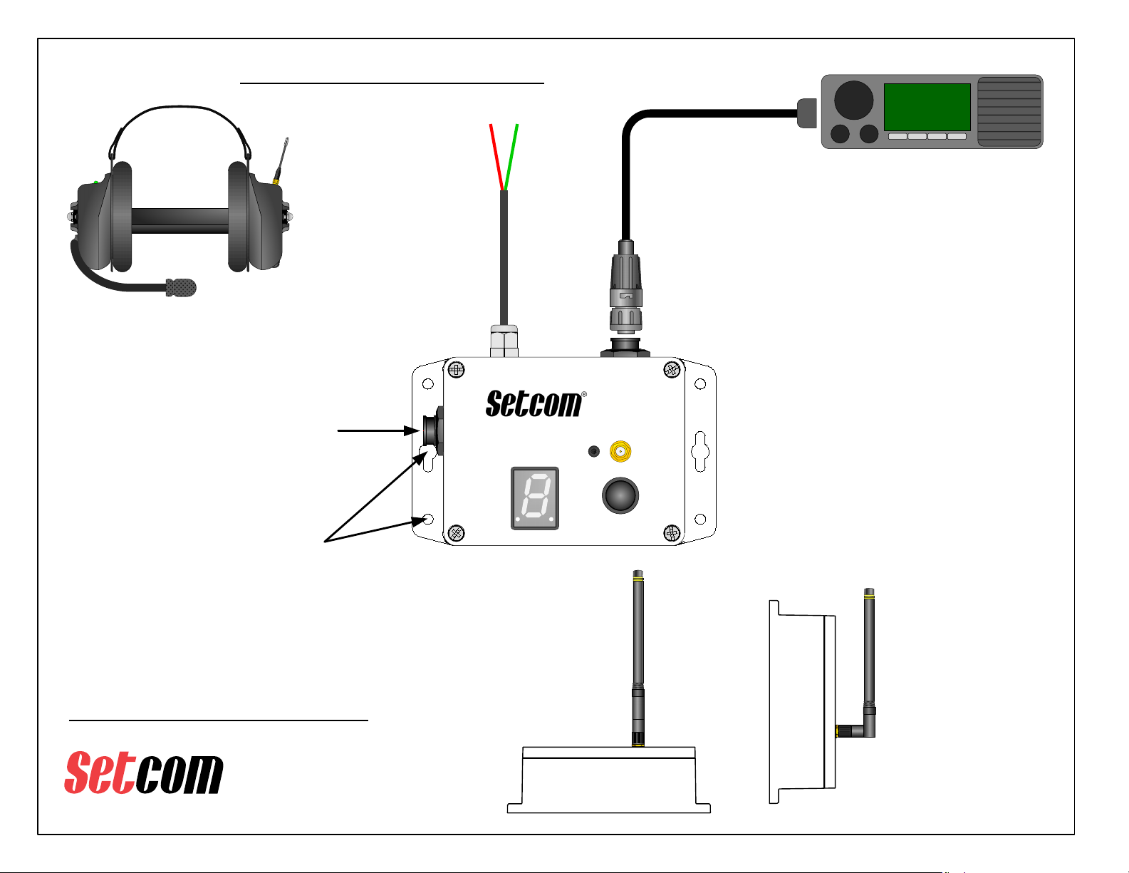
To install antenna, carefully
thread it onto the gold connector
on top of the MS-900SPW4
28-2031
Wireless Antenna
NCS12S1212C
P3
BT
N
AN
T
RADIOPOWER
RRC
CHANNEL
SELECT
CHANNEL
Instructions for operating the LiberatorMAX Series headsets
can be found in the LiberatorMax Fire Users Guide
464.100
TAC 1
Mobile Radio
RC or RCB
Radio Cable
Radio Cable part number is determined by radio
manufacturer, model number, and length of cable
Mount the MS-900MAX using the 4
small mounting holes or the 2 larger
holes on the enclosure flanges.
Mounting screws supplied by user.
If 2 radios are required, a Setcom
RRC-950 can be connected to the
RRC Jack. Refer to the RRC-950
User Guide for more information.
Connect Power Cable
to DC Power Source,
12 to 24 VDC
RED = +V
GREEN = GND
MS-900MAX Typical Installation
3019 Alvin DeVane Blvd.
Ste. 560
Austin, TX 78741
Phone: (650) 965-8020
CORPORATION
®
TECH SUPPORT: 650-965-8020 ext. 703
Questions or technical issues? Please call:
Page 2 of 5
CSB-9xxMAX Wireless Headset
In a typical installation the
antenna is pointed directly
upwards as shown here
(or directly downwards for
ceiling/headliner mount)
If the MS-900SPW4 must be
installed on a vertical surface, it is
recommended to “fold” the antenna
so the main shaft is vertical
To orient the antenna, loosen the
connector, place the antenna in the
desired position, then re-tighten the
connector. Once the antenna
connector is tightened, do not try to
turn the antenna
The system will work
with the antenna
oriented horizontally,
but effective range may
be somewhat reduced
NCS12S12
12C
P3
B
T
N
A
N
T
RADIOPOWER
RRC
CHANNEL
SELECT
CHANNEL
The MS-900MAX should be mounted in a
location where the CHANNEL SELECT
button is accessible and the CHANNEL
indicator can be easily seen.

RX LEVEL
ADJUST
TX LEVEL
ADJUST RX RANGE
SWITCH
3019 Alvin DeVane Blvd.
Ste. 560
Austin, TX 78741
Phone: (650) 965-8020
CORPORATION
®
TECH SUPPORT: 650-965-8020 ext. 703
Questions or technical issues? Please call:
Page 3 of 5
RX Audio level is normally set by the volume
control on the mobile radio.
If further adjustment is needed, RX LEVEL
control can be used to adjust RX volume.
MS-900MAX Controls and Adjustments
TX Audio level is normally
factory-preset to the correct
level for the radio type specified
when the MS-900MAX is
ordered.
If a different TX level is required
the TX LEVEL can be set from
0 (highest) to F (lowest) to
accommodate various radios.
Call Setcom Tech Support for
assistance if needed.
MS-900MAX shown with top
cover removed
If RX LEVEL control does not provide enough
adjustment range, the RX RANGE switch can
be set to allow higher or lower level settings.
RX RANGE
SWITCH
(shown enlarged)
ONOFF
Section 2
Section 1
For Factory Calibration
DO NOT ADJUST
NOTE: Remove top cover carefully to make sure internal
cables, wiring, and ground contacts do not get damaged!
Inner Nut
NCS12S1212C
TXCAL
TX
LEVEL
RX
RANGE
RX
LEVEL
OFF ON
N O
1 2
Default is both sections
set to OFF
To increase RX Level,
set section 1 to ON
To decrease RX level,
set section 2 to ON
Do not set both sections
to ON, use only one
section or the other
3019 Alvin DeVane Blvd.
Ste. 560
Austin, TX 78741
Phone: (650) 965-8020
CORPORATION
®
TECH SUPPORT: 650-965-8020 ext. 703
Questions or technical issues? Please call:
Page 4 of 5
REGULATORY NOTICES
FCC Compliance Statement (Part 15.19)
This device complies with Part 15 of the FCC Rules.
Operation is subject to the following two conditions:
1. This device may not cause harmful interference, and
2. This device must accept any interference received,
including interference that may cause undesired
operation.
FCC Warning (Part 15.21)
Changes or modifications not expressly approved by the
party responsible for compliance could void the user’s
authority to operate the equipment.
FCC Rules IC Rules
IC RF Exposure Statement / Déclaration d’exposition d’IC RF
This device meets the IC requirements for RF exposure in
public or uncontrolled environments.
Cet appareil est conforme aux conditions de la IC en matière
de RF dans des environnements publics ou incontrôlée.
The antenna(s) used for this transmitter must be used to
provide a separation distance of at least 5 cm from all persons.
La ou les antennes utilisées pour cet émetteur doivent être
utilisées de manière à assurer une distance de séparation d'au
moins 5 cm de toute personne.
This transmitter with its antenna complies with FCC/IC RF
exposure limits for general population / uncontrolled exposure.
INSTALLATION AND USERS GUIDE
3019 Alvin DeVane Blvd.
Ste. 560
Austin, TX 78741
Phone: (650) 965-8020
CORPORATION
®
TECH SUPPORT: 650-965-8020 ext. 703
Questions or technical issues? Please call:
Page 5 of 5
INSTALLATION AND USERS GUIDE
FCC Part 15 Notice
This equipment has been tested and found to comply with the limits for a Class B digital device, pursuant to Part 15 of the FCC Rules.
These limits are designed to provide reasonable protection against harmful interference in a residential installation. This equipment
generates, uses and can radiate radio frequency energy and, if not installed and used in accordance with the instructions, may cause
harmful interference to radio communications. However, there is no guarantee that interference will not occur in a particular installation. If
this equipment does cause harmful interference to radio or television reception, which can be determined by turning the equipment off
and on, the user is encouraged to try to correct the interference by one of the following measures:
Reorient or relocate the receiving antenna.
Increase the separation between the equipment and receiver.
Connect the equipment into an outlet on a circuit different from that to which the receiver is connected.
Consult the dealer or an experienced radio/TV technician for help.
Table of contents
Popular Accessories manuals by other brands

NOKIAN TYRES
NOKIAN TYRES INTUITU quick start guide

Roger Technology
Roger Technology M90 Series instructions

Apogee
Apogee SO-110 owner's manual

Hobbywing Technology
Hobbywing Technology G3 Advance Gyro user manual

GAOMON
GAOMON PD156 PRO user manual

MediaRange
MediaRange MR749 User manual, Operating- and safety instructions, Warranty conditions


