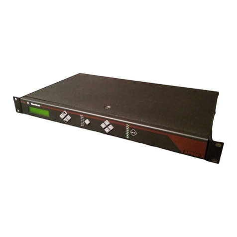
Settop M1-15 User manual

User Guide Settop M1-15 4G
FW 3.0.0 (200527rev.2)

2
Index
Index 2
About Settop M1 5
Features and specifications Settop M1 6
Communications 6
Multi Band LTE Cat 1 with 3G/2G Fallback 6
Wi-Fi 6
Bluetooth 6
Communication Ports 6
Electrical and operating requirements 6
Size and weight 6
Scheme Settop M1 7
Front View 7
Back View 10
Upper View 11
Receiver Installation 12
Weather conditions 12
Batteries and Power 12
Powering to Settop M1 12
Powering to other devices 12
Configuring the receiver 13
Default settings 13
Turn on Settop M1 14
Configuring via Wi-Fi 14
Configuring via PHONE 14
Configuring the receiver using web interface 16
System Status 17
SETTOPSURVEY, S.L. Bofarull 14, 08027 Barcelona (Spain) Phone: (+34) 93 340 05 73 Fax: (+34) 93 351 95 18 www.settopsurvey.com [email protected]

3
Logo 17
Menu 17
Data 17
IST Connect 17
Comunication 18
Temperature 19
Power 19
Total Station 19
Device Menu 21
TOTAL STATION 21
Start/Stop 21
Scheduler 21
Laser 23
Mode 23
Chg Face 23
Turn To 23
Level 24
Tracklight 24
Search 24
Ref. Circle 24
Video 25
Webcam 26
COMMUNICATIONS 28
Gateway 28
Modem 28
Wi-Fi 29
Bluetooth 30
Ethernet 30
Radio 31
SETTOPSURVEY, S.L. Bofarull 14, 08027 Barcelona (Spain) Phone: (+34) 93 340 05 73 Fax: (+34) 93 351 95 18 www.settopsurvey.com [email protected]

4
COM 31
ISTConnect 31
Devices 34
SYSTEM 35
Info 35
Autopower 35
Language 36
Update 36
Manage 37
Reboot 37
Project bar 38
Project 38
Targets 40
Add/ Measure 41
Messages 42
APPENDIX I - Installation Scheme 43
Basic Installation without UPS 43
Basic Installation with UPS 44
Installation with Settop OctoHub and UPS + Optic Fiber 45
APPENDIX II - FAQ (Frequently Asked Questions) 46
What to do if the receiver does not turn on. 46
The total station is not responding 46
APPENDIX III - Accessories and options 47
SETTOPSURVEY, S.L. Bofarull 14, 08027 Barcelona (Spain) Phone: (+34) 93 340 05 73 Fax: (+34) 93 351 95 18 www.settopsurvey.com [email protected]

5
About Settop M1
The SETTOP M1-15 is a communication device for remote Total Station monitoring, for use with a
Trimble S series Total Station with Finelock. Designed to work independently and autonomously in
topographic monitoring projects, the SETTOP M1-15 can be connected via Wifi, Bluetooth, Radio,
Ethernet, or GSM with SETTOPSurvey’s exclusive IST Connect cloud service. Based on the SETTOP M1
receiver, though without the integrated radio and GNSS/GPS technology, the SETTOP M1-15 allows you
to directly connect various additional sensors and record complete and precise measurements in any
project you undertake. Thanks to this unique feature, the SETTOP M1-15 can do much more than a
traditional GPS modem. In addition, its compact design and anodized aluminum casing make the
SETTOP M1-15 both light and robust, and its IP67 certification for resistance to dust and moisture
guarantee its functionality in all weather conditions.
SETTOPSURVEY, S.L. Bofarull 14, 08027 Barcelona (Spain) Phone: (+34) 93 340 05 73 Fax: (+34) 93 351 95 18 www.settopsurvey.com [email protected]

6
Features and specifications Settop M1
The Receiver Settop M1 has the following features:
Communications
Multi Band LTE Cat 1 with 3G/2G Fallback
● 3GPP Rel. 9 Compliant Protocol Stack
● Twelve Bands FDD-LTE: 700, 800, 850, 900, 1700/2100(AWS), 1800, 1900, 2100, 2600MHz
(bands 1,2,3,4,5,7,8,12,18,19,20,28)
● Seven Bands UMTS (WCDMA/FDD): 800, 850, 900, 1700/2100 (AWS), 1800, 1900 and 2100MHz
(bands 1,2,4,5,8,9,19)
● Quad Band GSM: 850, 900, 1800 and 1900 MHz
● Secure Connection with TLS
● Operating temperature: -40ºC to +90ºC
● RoHS compliant
Wi-Fi
● IEEE 802.11b/g
Bluetooth
● 2.0 + ERD (Enhanced Data Rate) wireless technology.
Communication Ports
● 1 RS232 Host Event port, PPS Power In/Out
● 1 USB OTG port Power In/Out
● 1 TNC connector for GPS antenna
● 2 FME connector for GSM antenna
● 1 Slot SIM card
● 1 Slot MicroSD card
Electrical and operating requirements
● External Power: 12 – 30 V.
● Power:
✔All components activated at full power: 12.8W
● Operating temperature -40º a 75º C
● Storage temperature -55º a 85º C
● Random vibe MIL-STD 810F (7.7g RMS)
● Vibe SAEJ1211 (4g)
● Bump/Shock IEC 68-2-27 (30g)
● IP67
Size and weight
● 1 Front Panel with 10 LED status indicators
● Size:
✔Width: 13.8 cm
✔Depth: 13.8 cm
● Height: 3.5 cm
● Weight: 0.6Kg
SETTOPSURVEY, S.L. Bofarull 14, 08027 Barcelona (Spain) Phone: (+34) 93 340 05 73 Fax: (+34) 93 351 95 18 www.settopsurvey.com [email protected]

7
Scheme Settop M1
For a good understanding of the equipment, please study the following diagrams
Front View
Post-process
Post-process (Green LED)
Status
Action
Turned Off
Doesn't store data
Constant
flashing 1s
Storing data
Fixed
Full memory
Power (Red LED)
Status
Action
Turned Off
Not connected
Flashing fast
and
continuous
Low battery
Fixed
Turned on
Flashing (1)
every 10s
Standby*
* Power on unit, but unit is turned off
SETTOPSURVEY, S.L. Bofarull 14, 08027 Barcelona (Spain) Phone: (+34) 93 340 05 73 Fax: (+34) 93 351 95 18 www.settopsurvey.com [email protected]

8
Bluetooth - Wi-Fi
Bluetooth (Green LED)
Status
Action
Turned Off
Not linked to any device
Flashing light
Linking to a device
Fixed
Device linked
Wi-Fi (Red LED)
Status
Action
Turned Off
Not linked to any network
Modulated light
Looking for a network Wi-Fi
Constant
flashing
(2 per
second)
AD-HOC Mode
Fixed
Network linked
Radio - Phone
Radio (Green LED)
Status
Action
Turned Off
Doesn’t use radio
Constant
flashing
(1 per
second)
Radio signal transmitting (e.g. Mode
Base)
Constant
flashing
(2 per
second)
Radio signal receiving (e.g. Mode Rover)
Phone (Red LED)
Status
Action
Turned Off
Doesn’t use phone
Fixed
Doesn’t have SIM CARD
Constant
flashing
(1 per
second)
GPRS Coverage
Constant
flashing
(2 per
second)
HSDPA Coverage
Constant rapid
flashing
Error
SETTOPSURVEY, S.L. Bofarull 14, 08027 Barcelona (Spain) Phone: (+34) 93 340 05 73 Fax: (+34) 93 351 95 18 www.settopsurvey.com [email protected]

9
Satellites - External devices
Satellites (Green LED)
Status
Action
Turned Off
Not receiving Satellites
Flashing “n”
constant
flashes
Receiving “n” Satellites
Constant rapid
flashing
Error
External devices (Red LED)
Status
Action
Turned Off
Device not linked
Constant
flashing
(1 per
second)
Total Station linked via USB
Constant
flashing
(2 per
second)
Total Station linked via bluetooth
Constant
flashing
(3 per
second)
Station connected via cable and
bluetooth
USB - RS232
USB (Green LED)
Status
Action
Turned Off
Device Disconnected
Constant
flashing
(2 per
second)
Device connected via USB in LEMO 2
RS232 (Red LED)
Status
Action
Turned Off
Device disconnected
Constant
flashing
(1 per
second)
Device connected via RS232 in LEMO1
Constant
flashing
(2 per
second)
Device connected via RS232 in LEMO2
SETTOPSURVEY, S.L. Bofarull 14, 08027 Barcelona (Spain) Phone: (+34) 93 340 05 73 Fax: (+34) 93 351 95 18 www.settopsurvey.com [email protected]

10
Constant
flashing
(3 per
second)
Device connected via RS232 in LEMO1
and LEMO 2
Constant
flashing
(1 Hz)
Service mode
Back View
Phone
GSM Antenna connector
COM1
Lemo connector for RS232/ power in
COM2
Lemo connector for USB / power in/out
Phone
GSM Antenna connector
Satellites
GPS Antenna connector
SETTOPSURVEY, S.L. Bofarull 14, 08027 Barcelona (Spain) Phone: (+34) 93 340 05 73 Fax: (+34) 93 351 95 18 www.settopsurvey.com [email protected]

11
Upper View
ON/OFF Button
1. Turn on the device by pressing the button.
2. Turn off the device by pressing the button for a few seconds, until the leds are flashing fast.
3. Reset password access: press the button 3 times when the device is on. The next time the Settop M1
WebUI is accessed (Shift+F5
), a dialogue box appears to create a new password.
SETTOPSURVEY, S.L. Bofarull 14, 08027 Barcelona (Spain) Phone: (+34) 93 340 05 73 Fax: (+34) 93 351 95 18 www.settopsurvey.com [email protected]

12
Receiver Installation
Weather conditions
The equipment is conforms to environment rating (IP67), which makes it dust-proof and protects it against
contact with solids and liquids and makes it able to withstand pressure and water leakage when the unit is
submerged to a maximum of 1m.
However, you must take reasonable care to keep the unit dry.
To improve the performance and long-term reliability of the receiver avoid exposing the receiver to extreme
environmental conditions, such as:
● Water
● Heat: above 75 ° C
● Cold: less than -40 ° C
● Liquids and corrosive gases
Batteries and Power
Powering to Settop M1
The receiver uses an external power source. If the receiver is not connected to an external power source or if
the external power supply fails, the receiver will shut down automatically without storing the data and
controlling external devices. The data that has been stored will not be lost. When the external power source
is restored, the computer will boot automatically with the last settings loaded. Autopower option must be
enabled (ON) in the System Settings section.
The battery supplied with the receiver Settop M1 is a rechargeable Settop Battery II LiFePO4 12.8V-5Ah
which allows continuous operation for up to 8 hours. Also, to ensure continuity of operation it can be
connected to the mains transformer with 12V - 32V.
Powering to other devices
Settop M1 can power other devices connected through the COM1 or COM2 slots. To do so, System Settings
must indicate on the bridge option the limit of power supply you want, cutting off at the time of peak
indicated.
Power limits are 10V, 15V, 20V, 25V and 30V.
The bridge is configured in both directions, that is, from COM1 to COM2 and COM2 to COM1.
WARNING: Before you activate the bridge, make sure that the computer can receive the maximum
voltage setting. Improper use of this option, can damage the computer, leaving it unusable.
SETTOPSURVEY, S.L. Bofarull 14, 08027 Barcelona (Spain) Phone: (+34) 93 340 05 73 Fax: (+34) 93 351 95 18 www.settopsurvey.com [email protected]

13
Configuring the receiver
IMPORTANT
:Check the Serial Number before starting to connect. Older Serial Numbers (up to
M10000300), please contact to [email protected]
Default settings
The Settop M1 receiver comes with a default configuration to start a job easily.
The configuration of SETTOP M1 default state is:
● Main user
○Username: admin *
○Password: No password defined
● Station not connected
● Wi-Fi configured in ACCESS POINT
○IP Address: 192.168.2.2
● IP Ethernet Adapter: 192.168.11.98
○ Subnet MASK: 255.255.255.0
○ Gateway: 192.168.11.1
● Bluetooth without any link
● Telephone not configured
● System:
○ Autopower: on
○ Bridge: Power Limit 15V
○ Language: English
SETTOPSURVEY, S.L. Bofarull 14, 08027 Barcelona (Spain) Phone: (+34) 93 340 05 73 Fax: (+34) 93 351 95 18 www.settopsurvey.com [email protected]

14
Turn on Settop M1
When you received SETTOP M1 for the first time, it is necessary to set a minimum setting. You can follow
this setting Step by Step:
Configuring via Wi-Fi
● Step 1:
○ Connect Power Cable (PN. 310655-v3
) in COM1
○ Connect Total Station cable (PN: 310605
) in COM2
● Step 2:
Press the ON/OFF button and wait until the OS Boots Up. Wi-Fi LED flashes modulate (see diagram in
section 1.4 Settop M1 Scheme) when searching for a network and Wi-Fi LED flash 2 times per second
● Step 3:
With a PC, smartphone (Android), iPhone or iPad with Wi-Fi Access, press “search network”
. It will appear
as one network called “Settop M1 SN”
(SN is a serial number).
● Step 4:
Enter Network password “settopm1” (in lowercase).
● Step 5:
Open your Internet browser (it supports Google Chrome and Safari) and key in IP address 192.168.2.2
● Step 6:
○ User name is: admin
○ Password: The password defined for the first time that access to web (or m1)
Configuring via PHONE
● Step 1:
○ Connect Power Cable (PN. 310655-v3
) in COM1
○ Connect Total Station cable (PN: 310605
) in COM2
● Step 2:
Press the ON/OFF button and wait until the OS Boots Up. Phone LED flashes constantly (one or two times
per second) (see diagram in section 1.4 Settop M1 Scheme).
● Step 3:
With a PC, iPhone or iPad, open your Internet browser (it supports Google Chrome and Safari) and key in
static IP address assigned at SIM card.
● Step 4:
✔
User name is: admin
✔
Password: The password defined for the first time that access to web (or m1)
SETTOPSURVEY, S.L. Bofarull 14, 08027 Barcelona (Spain) Phone: (+34) 93 340 05 73 Fax: (+34) 93 351 95 18 www.settopsurvey.com [email protected]

15
Sources of electrical interference
High power signals from a nearby radio or radar transmitter can overwhelm the receiver circuits. This does
not harm the instrument, but can prevent the electronic receiver from working properly.
Avoid placing the receiver or antenna at least 400 meters from the following sources of electricity and / or
magnetic noise:
● Powerful Radar
● Gasoline engines (spark plugs)
● TVs and computer monitors
● GNSS antennas.
● Alternators and generators
● Electric motors
● Equipment with DC-AC converters
● Fluorescent lights
● Switching power supplies
Low-power transmitters such as cell phones and two-way radios normally do not interfere with the operation
of the receiver.
It is recommended that you use an uninterruptible power supply (UPS) to power the receiver. A UPS protects
equipment from surges and spikes, and keeps the receiver operating during power outages of short duration.
For more information, contact Settop Survey ([email protected]).
SETTOPSURVEY, S.L. Bofarull 14, 08027 Barcelona (Spain) Phone: (+34) 93 340 05 73 Fax: (+34) 93 351 95 18 www.settopsurvey.com [email protected]

16
Configuring the receiver using web interface
The Web UI of the Settop M1 has been designed to be a “responsive” website that adapts to the type of
screen depending on the device used. It does not require any software installation, this means that you only
need to connect to this website via the Internet or via a local network. The user interface is really easy to use
with all the system information just by accessing it.
The page is divided into 4 sections: the main screen (1), the device menu (2), the system status (3) and the
project bar (4)
1) Main Screen
In the central part, there is all the space to interact and configure your receiver using the option that allows
the device to work. When an option is selected, all options are displayed in the right sidebar.
2) Device Menu
Access to the device configuration appears on the left side menu
3) System status
At the top, a summary of the current system configuration is shown, with all the basic information
4) Project bar
In the lower bar, the buttons with the actions to be performed appear (Measure, add targets, create
projects, save, etc).
SETTOPSURVEY, S.L. Bofarull 14, 08027 Barcelona (Spain) Phone: (+34) 93 340 05 73 Fax: (+34) 93 351 95 18 www.settopsurvey.com [email protected]

17
System Status
The top bar in the browser, informs us of the current settings of the receiver SETTOP M1.
Logo
The first icon of the bar is the device logo. By pressing on it, you can see basic information such
as the serial number and the firmware version installed
Menu
By pressing the following button, the left side menu appears for the configuration of the Total
Station, Communications and System. Pressing a second time, the menu disappears.
Data
The following icon shows the information of the current system date and UTC time
IST Connect
The ISTConnect icon refers to the way it is connected and the state it is in
(connected in green and disconnected in red). Pressing on it, a menu appears with the basic connection
information: the Status, the User and the URL
SETTOPSURVEY, S.L. Bofarull 14, 08027 Barcelona (Spain) Phone: (+34) 93 340 05 73 Fax: (+34) 93 351 95 18 www.settopsurvey.com [email protected]

18
Communication
The following logo refers to the way the Settop M1 is connected,
automatically detects the mode.
The Settop M1 can be connected by Ethernet cable (using the Settop OctoHub accessory), by telephone or
by Wi-Fi. In all the options, pressing on the icon the basic information associated to the connection appears.
SETTOPSURVEY, S.L. Bofarull 14, 08027 Barcelona (Spain) Phone: (+34) 93 340 05 73 Fax: (+34) 93 351 95 18 www.settopsurvey.com [email protected]

19
Temperature
The thermometer icon indicates the temperature read by the sensor in degrees Centigrade. Pressing on the
icon a drop-down appears
Power
The battery symbol indicates voltage level received for the receiver. Pressing on the icon a drop-down
appears.
The battery levels are divided into 5 states ranging from 0% to 100%
Battery level:
0%
1-25
%
25-50
%
50-75
%
75-100
%
NOTE: In a state of continuous power, the voltage will remain stable.
Total Station
The last icon corresponds
to the Total Station (TS) and indicates the status in which the TS is located. The states can be 3:
●Connected and measuring:
the angles are shown in Centesimal degrees (there is no option to
change the units) and the measurement method:
○ A:
Autolock
○ FL:
FineLock
○LR
: FineLock Long Range
○ DR:
Direct Reflex
○ M:
Manual
● Waiting
for the next round and the remaining time to start the next one
● Not attached
In all of them, clicking on the icon shows us information about the device
SETTOPSURVEY, S.L. Bofarull 14, 08027 Barcelona (Spain) Phone: (+34) 93 340 05 73 Fax: (+34) 93 351 95 18 www.settopsurvey.com [email protected]

20
By pressing “Configuration”, the activation of the Total Station Service that allows the Settop M1 to control
the Total Station is opened on the main page. It can also be accessed from:
Once the status has been modified, press "Save" for the changes to take effect. With the service-disabled, it
is an external software that controls the station.
NOTE: It is recommended to have this option activated.
SETTOPSURVEY, S.L. Bofarull 14, 08027 Barcelona (Spain) Phone: (+34) 93 340 05 73 Fax: (+34) 93 351 95 18 www.settopsurvey.com [email protected]
Table of contents

