4
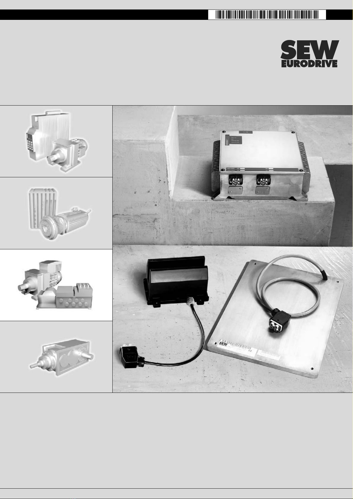
Operating Instructions – MOVITRANS® THM10C / THM10E Pick-Ups
1Important Notes
Betriebsanleitung
1 Important Notes
Explanation of
symbols of safety
and warning
instructions
Always follow the safety and warning instructions in this documentation.
A requirement of fault-free operation and fulfillment of any rights to claim under
limited warranty is that you adhere to the information in the operating instructions.
Read the operating instructions before you start operating the unit!
The operating instructions contain important information about service and should
be kept near the unit.
Designated use
The MOVITRANS®THM10C and THM10E pick-ups are used for the mobile elements
of an energy transfer system equipped with MOVITRANS®. Observe all information on
the technical data and the permitted conditions where the unit is operated.
Do not start up the unit (take it into operation in the designated fashion) until you have
established that the machine complies with the EMC Directive 89/336/EEC and that the
conformity of the end product has been determined in accordance with the Machinery
Directive 98/37/EEC (with reference to EN 60204).
The rules and regulations of the Professional Association (Berufsgenossenschaft, BG),
in particular BG rule B11 "Electromagnetic fields", must be observed during installation,
startup and operation of systems with contactless energy transfer by induction for use
in industrial workplaces.
Hazard
Possible consequences: Severe or fatal injuries.
Hazardous situation
Possible consequences: Slight or minor injuries.
Harmful situation
Possible consequences: Damage to the drive and the environment.
Tips and useful information.
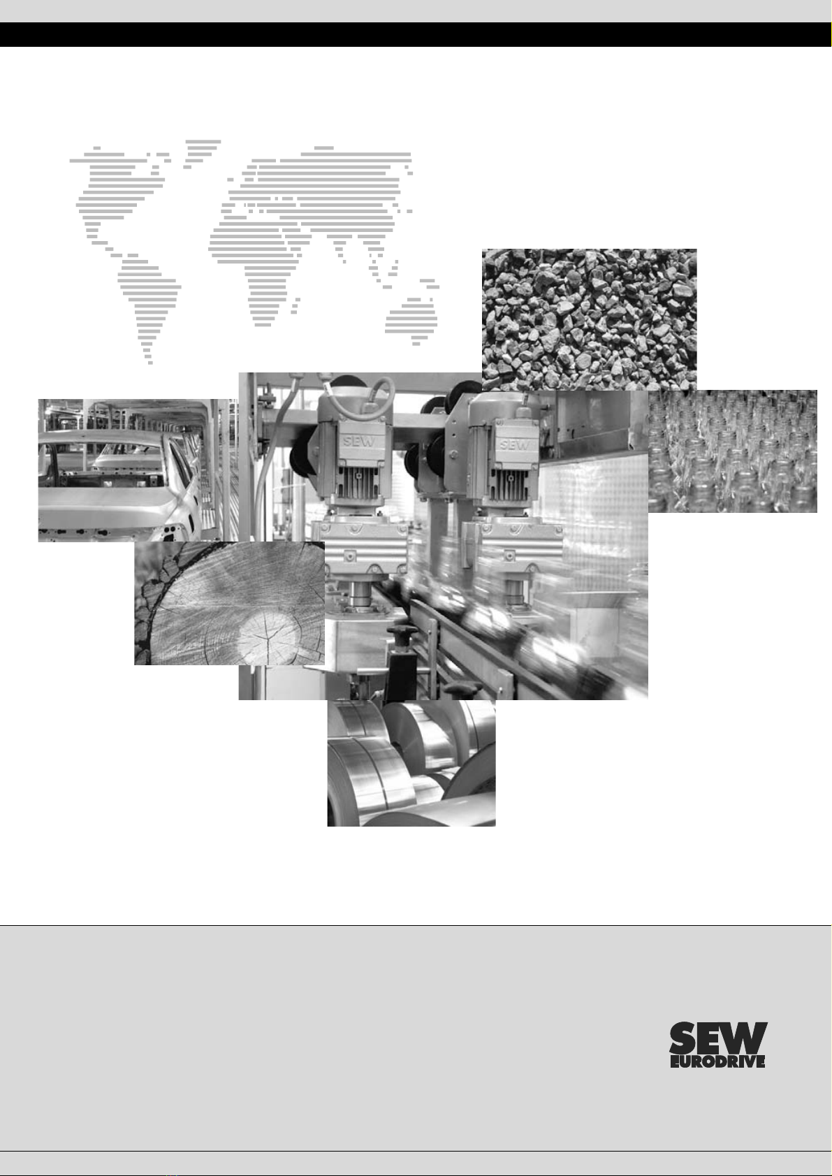
The MOVITRANS®THM10C and THM10E pick-up units are designed for the operation
of contactless energy transfer systems for industrial and commercial plants.
MOVITRANS®THM10CTHM10E may only be operated with the prescribed and
suitable adapters, such as MOVITRANS®TPM12B.