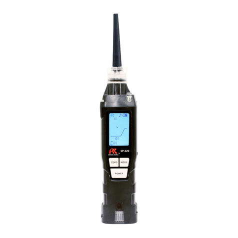
sewerin EX-TEC PM 580 User manual

14.01.2020 a – 107707 – en
EX-TEC®PM 580/550/500/400
Operating Instructions

Device
Fig. 1: Front view
Fig. 2: Rear view
Signal light
Display
Menu key
Up key
Enter key
Down key
ON/OFF key
Buzzer
Gas input
Filter fastener
Belt clip with D-ring
Battery compartment

Display
Fig. 3: Display in measuring mode - Structure application
Measurement value 1:
– Bar graph with
quasi-logarithmic scale
– Measurement value, gas, unit
Measurement value 2:
– Measurement value, gas, unit
Application
Remaining capacity (disposable/rechargeable battery)
Fig. 4: Display in measuring mode
Left image: Warning application
Right image: Measuring application

Illustration of warnings in this document
ADANGER!
Risk of personal injury. Will result in serious injury or death.
AWARNING!
Risk of personal injury. Can result in serious injury or death.
NOTICE!
Risk of damage to property.

Contents│ I
1 Introduction .............................................................................1
1.1 Information about this document...............................................1
1.2 Purpose.....................................................................................2
1.3 Intended use .............................................................................2
1.4 Improper use .............................................................................2
1.5 Safety information .....................................................................3
1.6 Qualicationofusers.................................................................5
2 Product description ................................................................6
2.1 Product variants ........................................................................6
2.2 Application options ....................................................................7
2.2.1 Detectable gases ...................................................................7
2.2.2 Applications............................................................................8
2.3 Features ....................................................................................9
2.3.1 Sensors..................................................................................9
2.3.2 Gas types ............................................................................. 11
2.3.3 Visual and audible signals.................................................... 11
2.3.3.1 Overview ........................................................................... 11
2.3.3.2 Alarm signals.....................................................................12
2.3.3.3 Operating signal................................................................13
2.3.3.4 Signals in the event of faults .............................................13
2.3.4 Display illumination ..............................................................13
2.3.5 Gasinputandlter...............................................................13
2.3.6 Belt clip and short probe ......................................................14
2.4 Additional probes ....................................................................15
2.5 Measuring mode and menu ...................................................15
2.6 Units for concentration data ....................................................17
2.6.1 Selectable units (warning)....................................................17
2.6.2 Conversion of the concentration data ..................................17
3 Operation ...............................................................................18
3.1 Switching on the device ..........................................................18
3.2 Switchodevice .....................................................................21
3.3 Navigating ...............................................................................22
3.3.1 Orientation aids on the display.............................................22
3.3.2 Key functions........................................................................24
3.3.3 Switch between levels..........................................................25
3.3.3.1 Changing from measuring mode to menu or measuring
menu .................................................................................25

II │Contents
3.3.3.2 Switch from menu or the measuring menu into
measuring mode ...............................................................25
3.3.3.3 Select a menu item in a menu...........................................26
3.3.3.4 Cancel the action or process.............................................26
3.3.4 Scrolling ...............................................................................26
3.3.5 Select values........................................................................27
3.3.6 Queries - perform action or don’t perform an action ............27
3.3.7 Lists - view detailed information ...........................................28
3.3.8 Write comment .....................................................................28
3.4 Start, stop, save recording ......................................................30
3.4.1 Start recording......................................................................31
3.4.2 Stop recording and save without a comment .......................31
3.4.3 Stop recording and save it with a comment .........................32
3.5 Change application .................................................................32
3.6 Set zero point ..........................................................................33
3.7 Change gas type .....................................................................35
3.8 Changing the settings on the device .......................................36
3.9 Concentration-dependent signal (structure)............................37
3.10 Leak test when using probes ..................................................38
3.11 Changingthelter..................................................................39
4 Settings ..................................................................................42
4.1 General information about the settings ...................................42
4.2 Settings using the GasCom software......................................42
4.3 Settings on the device.............................................................43
4.3.1 Access to the settings using PIN code.................................43
4.3.2 Adjustment ...........................................................................44
4.3.3 Restore.................................................................................44
4.3.4 Date/time..............................................................................45
4.3.5 PPM threshold......................................................................45
5 Protocols and information ...................................................46
5.1 Protocols .................................................................................46
5.2 Information ..............................................................................48
6 Maintenance ..........................................................................51
6.1 Scope of maintenance (overview)...........................................51
6.2 Test gases ...............................................................................52
6.2.1 Utilisable test gases .............................................................52
6.2.2 Available test gases .............................................................52

Contents│ III
6.3 Suitable environment ..............................................................53
6.4 Device inspection ....................................................................53
6.4.1 Ways of carrying out the procedure ....................................53
6.4.2 Frequency and due date ......................................................54
6.4.3 Variants of the guided device inspection
(standard and ECO).............................................................55
6.4.4 Features...............................................................................56
6.4.5 Presentation of results .........................................................57
6.4.6 Required accessories...........................................................58
6.4.7 Perform a device inspection ................................................58
6.4.7.1 Requirements (summary)..................................................58
6.4.7.2 Start device inspection......................................................58
6.4.7.3 Checking the device condition ..........................................59
6.4.7.4 Testing the pump...............................................................59
6.4.7.5 Testing the zero point........................................................60
6.4.7.6 Test the indication accuracy (standard device inspection) 60
6.4.7.7 Performing a bump test (ECO device inspection).............61
6.4.7.8 Save the device inspection ...............................................61
6.4.8 Measuring response time.....................................................62
6.5 Adjustment ..............................................................................62
6.5.1 Frequency ............................................................................62
6.5.2 Features...............................................................................62
6.5.3 Presentation of results .........................................................63
6.5.4 Required accessories...........................................................64
6.5.5 Performing an adjustment ....................................................64
6.5.5.1 Requirements (summary)..................................................64
6.5.5.2 Warning application...........................................................65
6.5.5.3 Measuring application .......................................................66
6.5.5.4 Structure application .........................................................67
6.6 Servicing .................................................................................68
7 Power supply.........................................................................69
7.1 Overview .................................................................................69
7.2 Approved disposable batteries and rechargeable batteries ....70
7.3 Rechargeable batteries ...........................................................71
7.3.1 Charging mode.....................................................................71
7.3.1.1 Required accessories........................................................72
7.3.1.2 Charging the batteries.......................................................72
7.3.2 Rechargeable battery servicing............................................73
7.4 Alarm at undervoltage .............................................................73
7.5 Changing the disposable/rechargeable batteries....................74

IV │Contents
8 Faults and problems .............................................................76
8.1 Error messages.......................................................................76
8.2 Warning messages..................................................................77
8.3 Resolution of problems ...........................................................77
8.3.1 Device has sucked water in .................................................77
8.3.2 Temporary zero point cannot be set.....................................79
9 Appendix................................................................................80
9.1 Technical data .........................................................................80
9.2 Sensors ...................................................................................83
9.2.1 Infrared sensors ...................................................................83
9.2.2 Semiconductor sensor .........................................................86
9.2.3 Catalytic combustion sensor ................................................87
9.2.4 Electrochemical sensors ......................................................89
9.2.5 Measuring ranges in the applications (overview) .................93
9.3 Test gases ...............................................................................94
9.3.1 Preset test gases .................................................................94
9.3.2 Setting ranges ......................................................................96
9.4 Alarms .....................................................................................97
9.4.1 Features...............................................................................97
9.4.2 Setting ranges ......................................................................99
9.4.2.1 Alarms AL1, AL2..............................................................100
9.4.2.2 LEL (end of measuring range) ........................................100
9.4.3 Alarm thresholds (condition at delivery) .............................100
9.5 Limit values for device inspection .........................................101
9.6 Explosion protection..............................................................101
9.6.1 Passive explosion protection..............................................101
9.6.2 Active explosion protection ................................................102
9.7 Deviceidentication ..............................................................103
9.8 Symbols on the display .........................................................104
9.9 Accessories and consumables..............................................109
9.10 Care ...................................................................................... 111
9.11 Advice on disposal ................................................................ 111
9.12 Legal basis ............................................................................ 112
9.13 Declaration of conformity ...................................................... 113
9.14 Abbreviations ........................................................................ 113
9.15 Technical terms ..................................................................... 114
10 Index..................................................................................... 116

1 Introduction│ 1
1 Introduction
1.1 Information about this document
This document is a component part of the product.
●Read the document before putting the product into operation.
●Keep the document within easy reach.
●Pass this document on to any subsequent owners.
● Unlessotherwisespecied,theinformationinthisdocument
refers to the product as delivered (factory settings) and applies
to all product variants.
●
The product is described with all device features. Not all of
the functions described may be available on the product you
are using. Please contact the SEWERIN sales department for
further information.
●Contradictory national legal regulations take precedence over
the information in this document.
Translations
Translations are produced to the best of our knowledge. The
original German version is authoritative.
Right of reproduction
No part of this document may be edited, duplicated or circulated
in any form without the express consent of Hermann Sewerin
GmbH.
Registered trademarks
Registered trademarks are generally not indicated in this docu-
ment.

2 │1Introduction
1.2 Purpose
The device is a portable gas concentration measuring device for
detection, measuring and warning.
The device can be used for:
●Pinpointing leaks in gas pipes that are not underground
●Assessment of the risk of explosion in work areas
● Identicationofgascomponents
The device is suitable for the following applications (/3/):
●Warning
●Measuring
●Structure
1.3 Intended use
The product is suitable for the following uses:
●professional
●industrial
●commercial
Theproductmustonlybeusedfortheapplicationsspeciedin
section 1.2.
The gases that can be measured with the product depend on
the product variant and the selected device features. For more
detailed information please see section 2.
The product can be used at operating temperatures up to 40°C.
However, high temperatures can reduce the lifetime of the sen-
sors, disposable batteries and rechargeable batteries.
1.4 Improper use
The product must not be used for:
●Pinpointing leaks in underground gas pipes
●Gas analysis of technical processes
●Monitoring liquids

1 Introduction│ 3
1.5 Safety information
This product was manufactured in keeping with all binding legal
and safety regulations.
The product has been tested for explosion protection by:
●TÜV Nord (ATEX)
●TUN (IECEx)
The product is safe to operate when used in accordance with the
instructions provided. However, when handling the product, there
may be risks to persons and property. For this reason, observe
the following safety information without fail.
●Observe all the applicable safety standards and accident pre-
vention regulations.
●Use the product only as intended.
●
Donot makeany changesor modications tothe product
unless these have been expressly approved by Hermann
Sewerin GmbH.
●
Only use accessories and consumables approved by Hermann
Sewerin GmbH.
●Always observe the permitted operating and storage temper-
atures.
●Handle the product carefully and safely, both during transport
and when working.
●Do not use the product if it is damaged or faulty.
● Whenthedevicehassueredanimpact(suchasbeingacci-
dentally dropped):
−Then perform a device inspection.1
●Protect the ports and sockets against dirt, and electrical ports
in particular against moisture.
1For the PM 400 SEWERIN also recommends: If the LEL sensitivity devi-
ates by more than 20%, replace the CC sensor.

4 │1Introduction
Explosion protection
●Do not operate the device in oxygen-enriched atmospheres,
otherwise the device will not be explosion-proof.
●The device must not be stored or operated in explosive envi-
ronments if there is a chance of strong electrostatic charges
occurring (e.g. from fast moving particles, hydraulically pro-
pelled liquids, pneumatically extracted dust or materials, in
electrostatic coating processes).
Maintenance
●Perform device inspection and adjustment only in well venti-
lated rooms or outdoors.
●Handle test gases in a professional manner.
Sensors
●Have sensors replaced by SEWERIN Service when their ser-
vice life has expired.
●
SEWERIN recommends: Perform a device inspection when
the device has been exposed to gas concentrations above the
end of measuring range.
Special environments
●
Substances containing silicone, and silicone vapours, can con-
taminate the sensors.
−
Do not allow the device to come into contact with substances
containing silicone.
−Use the device only in a silicone-free environment.
●
The device complies with the requirements of Directive
2014/30/EU (EMC). When using the product close to devices
with radio transmitters:
−Comply with the information in the operating instructions for
the devices regarding emission of interference.
●When used in mines:
−Use the device only in environments where there is a low
risk of mechanical impacts.

1 Introduction│ 5
1.6 Qualication of users
The appropriate specialist knowledge is required for using this
product. In addition, certain activities performed with the device
oronitmaybeperformedonlybyqualiedpersons.
A distinction is made between the following user groups:
Trained person
−
Trained persons know the external structure, functions and
operating instructions of the devices.
−They detect defects or changes to the device.
−
Trained persons may perform device inspections. They can
evaluate the results.
Specialist (device inspector)
−Specialists have received professional training and thus have
fundamental knowledge of the measuring principles used in
gas concentration measuring devices.
−
They are experienced users and therefore have sucient
knowledge of the use of gas concentration measuring devices.
−
Specialists are permitted to perform device inspections and
adjustments. They can evaluate the results.
Competent person
SEWERIN service personnel and people trained by SEWERIN
are competent persons.
−Competent persons have knowledge of the applicable regula-
tions and guidelines as well as the tasks and functions of gas
concentration measuring devices.
−They can evaluate whether the condition of devices renders
them safe to operate and can perform the necessary opera-
tions without supervision.
−Competent persons are appointed by their company in writing.
Theirresponsibilitiesaredenedwhentheyareappointed.
They are authorised by the manufacturer.
−Competent persons must receive regular training.
−
Competent persons are permitted to perform device inspec-
tions, adjustments and maintenance.

6 │2Productdescription
2 Product description
2.1 Product variants
The following product variants of the device are available:
●Ex-TEC PM 580 (for short: PM 580)
●Ex-TEC PM 550 (for short: PM 550)
●Ex-TEC PM 500 (for short: PM 500)
●Ex-TEC PM 400 (for short: PM 400)
Each product variant has certain basic device features as stand-
ard.Inaddition,therearedierentdevicefeaturesforeachprod-
uct variant:
−The built-in sensors can be set up for various gas types.
−Other sensors can be installed as options.
Note:
Thedevicefeaturesmustbespeciedatthetimeofpurchase.
● Asarule,optionalsensorscannotgenerallyberetrotted.

2 Product description│ 7
2.2 Application options
2.2.1 Detectable gases
The device may be used to measure the following gases:
Gas PM 580 PM 550 PM 500 PM 400
Methane CH4× × × ×
Propane C3H8o o o o
Nonane C9H20 – – – o
Carbon dioxide CO2o o o o
Oxygen O2o o o o
Carbon monoxide CO o o o o
Hydrogen sulphide H2S o o o –
Acetylene C2H2– – – o
Hydrogen H2– – – o
JFuel – – – o
× as standard, o optional, – not possible
The gases that can actually be measured with a device depend
on the device features with optional sensors and on the gas types
for which the device is set up.
AWARNING! Risk to life from dangerous
gas concentrations
Incorrect measurements may be obtained if nonane and
JFuel are measured using unsuitable accessories.
IfnonaneandJFuelaretobemeasured,tthenecessary
accessories:
●
Use only the accessories approved for this purpose
(section 9.6.2).

8 │2Productdescription
2.2.2 Applications
Thefollowingapplicationsaredierentiatedforworkingwiththe
device (/3/):
Application Activities
Warning – monitoring of work areas
– warning of toxic gas concentrations
– warning of lack of oxygen/excessive oxygen
– warning of explosive gas concentrations
Measuring – demonstrating gas purity / absence of gas
in gas pipes
Structure – measuring very small gas concentrations in
structures.
– locating the source of gas
The product variants are suitable for the following applications:
Application PM 580 PM 550 PM 500 PM 400
Warning × × × ×
Measuring × × – –
Structure × – – –
× as standard, – not possible

2 Product description│ 9
2.3 Features
2.3.1 Sensors
The sensors included as device features depend on the product
variant. The following sensors are included as standard or as
options:
Sensor Gas/gas type PM 580 PM 550 PM 500 PM 400
IR CH4
C3H8
× × × –
CO2o o o o
SC CH4
C3H8
× – – –
CC CH4
C3H8
C9H20
C2H2
H2
JFuel
– – – ×
EC CO o o o o
O2o o o o
H2S o o o –
× as standard, o optional, – not possible
When charging, the device shows which optional sensors are
included (Fig. 46).
Operating principles of the sensors
Sensor Operating principle
IR Infrared sensor absorption by infra-red-active
gases
SC Gas-sensitive
semiconductor
reacts to changes in conductivity
brought about by reducible gases
CC Catalytic combustion
sensor
catalytic combustion
EC Electrochemical
sensor
electrochemical cell

10 │2Productdescription
Technical information about the sensors, including their meas-
urement ranges, can be found in section 9.2.
Information about electrochemical sensors
Very high gas concentrations can reduce the lifetime of electro-
chemical sensors.
Information about semiconductor sensors and catalytic
combustion sensors
Thesesensorsaresensitivetoexternalinuences.
−
Oxygen-decientatmospherescanreducethesensitivityofthe
sensor(sensorsuocation).
−Gaseous components of silicones, oils and phosphate esters
etc. can irreversibly damage the sensor.
−Contamination of the measuring environment with halogens,
burnt neoprene, PVC, trichloroethylene etc. will also reduce
the sensitivity of the sensor. However, the sensor can usually
regenerate itself during further operation.

2 Product description│ 11
2.3.2 Gas types
By default the device is set up for gas type methane CH4.
However,thesensorsttedtoadeviceasstandard(section 2.3.1)
can be set up for other gas types or for additional gas types.
The following gas types can be set up:
Gas type PM 580 PM 550 PM 500 PM 400
CH4× × × ×
C3H8o o o o
C9H20 – – – o
C2H2– – – o
H2– – – o
JFuel – – – o
× as standard, o optional, – not possible
The gas types can be set up:
−when the device is purchased
−subsequently using GasCom software1
You can switch between all gas types for which a device is set
up during operation (section 3.7).
2.3.3 Visual and audible signals
2.3.3.1 Overview
The device can emit the following signals:
●visual signal (via the signal light)
●audible signal (via the buzzer)
The two signal types are displayed together.
1The new gas type is available in the device only when an adjustment has
been performed after setting up.

12 │2Productdescription
Signals are emitted at:
●Alarm
●Error (error message)
●Device inspection or inspection due2
●Warning, information
● Switchdeviceonando
There are also signals as:
●Operating signal
●concentration-dependent signal
2.3.3.2 Alarm signals
Warning alarms are emitted if the concentration of one or more
gases exceeds certain limit values (alarm thresholds).
AWARNING! Risk to life from dangerous gas concen-
trations
An alarm always indicates danger.
●Immediately take all necessary measures for your own
safety and the safety of others.
The concrete measures depend on the situation.
●In the event of a pre-alarm AL1 itmaybesucientto
ventilate thoroughly.
●In the event of a main alarm AL2 it may be necessary
to leave the danger zone immediately.
Acknowledgement
Under certain conditions, the audible signal can be muted during
alarms. In some measurement situations, the visual signal and
symbol can also be deactivated. The process is referred to as
acknowledgement.
2Signals when device inspections are due are issued only if the guided
device inspection has been activated using the GasCom software.
This manual suits for next models
3
Table of contents
Other sewerin Gas Detector manuals
