sewerin EX-TEC SNOOPER H User manual

Instructions
Wir sichern Lebensqualität.
Operating-
102729

Measurable success by Sewerin equipment
You settled on a precision instrument.
A good choice!
Our equipment stands out for guaranteed safety, optimal output and efficiency.
They correspond with the national and international guide-lines.
These operating instructions will help you to handle the instrument quickly and
competently.
Please pay close attention to our operating instructions before usage.
In case of further queries our staff is at your disposal at any time.
Yours
Hermann Sewerin GmbH
Robert-Bosch-Straße 3
D-33334 Gütersloh
: +49 - (0) - 52 41/9 34-0
FAX : +49 - (0) - 52 41/9 34-4 44
http:// www.sewerin.com

1
Design of the: EX-TEC® SNOOPER H

2
Notes

3
EX-TEC® SNOOPER H
Operating InstructionsOperating Instructions
Operating InstructionsOperating Instructions
Operating Instructions ................
................
........ pages 3 - 32pages 3 - 32
pages 3 - 32pages 3 - 32
pages 3 - 32
102729 - 05/27.11.1998

4
For your safety *For your safety *
For your safety *For your safety *
For your safety *
Thelawgoverningtechnicalequipment(theLawontheSafetyofAppliances)
of 24.06.1968 (BGBl.I, page 717) as amended by the Amendment Law of
13.08.1979 (BGBl.I, page 1432) requires the following matters to be drawn
to your attention:
Comply with the Operating Instructions.Comply with the Operating Instructions.
Comply with the Operating Instructions.Comply with the Operating Instructions.
Comply with the Operating Instructions.
Before operating or adjusting the appliance you must be thoroughly familiar
with this operating manual. You must comply with it in every respect.
The appliance is designed only for the application described and for
industrial (commercial) use.
Liability for Function or DamageLiability for Function or Damage
Liability for Function or DamageLiability for Function or Damage
Liability for Function or Damage
Liability for the functioning of the appliance passes to the owner or operator
in all cases in which the appliance has been improperly maintained or
repaired by persons not associated with SEWERIN Service or if it has been
used for a purpose not in accordance with its designated application.
You should therefore always use original SEWERIN accessories with the
EX-TEC® SNOOPER H.
Hermann Sewerin GmbH accepts no responsibility for damage due to a
failure to comply with the foregoing instructions. The guarantee and liability
terms of the Hermann Sewerin GmbH terms of sale and supply are not
extended by the foregoing.
We reserve the right to make technical changes in the course of continued
development.
HERMANN SEWERIN GMBH
* All references to laws, statutes and norms relate to the legislation of the Federal Republic of
Germany.

5
ContentsContents
ContentsContents
Contents pagepage
pagepage
page
For your safetyFor your safety
For your safetyFor your safety
For your safety ........................................................................................................................................................................
........................................................................................................................................................................
.................................................................................... 44
44
4
1.01.0
1.01.0
1.0 TheThe
TheThe
The EX-TEC® SNOOPER H ....................................................................................................................
....................................................................................................................
.......................................................... 66
66
6
1.1 Purpose ........................................................................................ 7
1.2 Tests ............................................................................................. 7
2.02.0
2.02.0
2.0 OperationOperation
OperationOperation
Operation ........................................................................................................................................................................
........................................................................................................................................................................
.................................................................................... 88
88
8
2.1 Switching on ................................................................................. 8
2.2 Measuring operation ..................................................................... 9
2.3 Concentration-dependent signal ................................................ 10
2.4 Alarms ......................................................................................... 11
2.5 Manual zero-point adjustment...................................................... 11
2.6 Battery monitoring....................................................................... 12
2.7 Switching off ............................................................................... 12
3.03.0
3.03.0
3.0 Charging techniqueCharging technique
Charging techniqueCharging technique
Charging technique..................................................................................................................................
..................................................................................................................................
................................................................. 1313
1313
13
4.04.0
4.04.0
4.0 Inspection, testing and maintenanceInspection, testing and maintenance
Inspection, testing and maintenanceInspection, testing and maintenance
Inspection, testing and maintenance........................................................................
........................................................................
.................................... 1515
1515
15
4.1 Test Set ...................................................................................... 16
4.2 Function testing .......................................................................... 17
5.05.0
5.05.0
5.0 AdjustmentAdjustment
AdjustmentAdjustment
Adjustment................................................................................................................................................................
................................................................................................................................................................
................................................................................ 1818
1818
18
6.06.0
6.06.0
6.0 Changing the sensor systemChanging the sensor system
Changing the sensor systemChanging the sensor system
Changing the sensor system..................................................................................................
..................................................................................................
................................................. 2121
2121
21
7.07.0
7.07.0
7.0 TT
TT
Technical notesechnical notes
echnical notesechnical notes
echnical notes................................................................................................................................................
................................................................................................................................................
........................................................................ 2222
2222
22
8.08.0
8.08.0
8.0 TT
TT
Technical dataechnical data
echnical dataechnical data
echnical data ....................................................................................................................................................
....................................................................................................................................................
.......................................................................... 2323
2323
23
9.09.0
9.09.0
9.0 AccessoriesAccessories
AccessoriesAccessories
Accessories............................................................................................................................................................
............................................................................................................................................................
.............................................................................. 2424
2424
24
10.010.0
10.010.0
10.0 Error messagesError messages
Error messagesError messages
Error messages ..............................................................................................................................................
..............................................................................................................................................
....................................................................... 2525
2525
25
11
11
11.01.0
1.01.0
1.0 Wearing partsWearing parts
Wearing partsWearing parts
Wearing parts ......................................................................................................................................................
......................................................................................................................................................
........................................................................... 2626
2626
26
EC-TEC-T
EC-TEC-T
EC-Type Examinations Certificateype Examinations Certificate
ype Examinations Certificateype Examinations Certificate
ype Examinations Certificate ....................................................................................................
....................................................................................................
.................................................. 2727
2727
27
Declaration of conformityDeclaration of conformity
Declaration of conformityDeclaration of conformity
Declaration of conformity ................................................................................................................................
................................................................................................................................
................................................................ 2929
2929
29
TT
TT
Test reportsest reports
est reportsest reports
est reports................................................................................................................................................................................
................................................................................................................................................................................
........................................................................................ 3030
3030
30

6
1.01.0
1.01.0
1.0 TheThe
TheThe
The EX-TEC® SNOOPER H
☞Please fold out the illustration inside the frontPlease fold out the illustration inside the front
Please fold out the illustration inside the frontPlease fold out the illustration inside the front
Please fold out the illustration inside the front
cover !cover !
cover !cover !
cover !
ItemItem
ItemItem
Item DescriptionDescription
DescriptionDescription
Description FunctionFunction
FunctionFunction
Function
1 detector key key position:
ñswitch detector on
ñmanually set zero point
òswitch detector off
2 LCD display display of:
lbattery capacity
lminimum sensitivity
lreadings
lerror messages
3 buzzer acoustic warning
4 alarm lamp optical warning
5 sensor cap changing sensors for:
lmanual probe
lswan-neck (large)
lswan-neck (small)
6 hole service button for:
lswitching off acoustic
signal
ladjustment mode
7 charging contacts connection to
charging adapter

7
1.11.1
1.11.1
1.1 PurposePurpose
PurposePurpose
Purpose
The EX-TEC® SNOOPER H gas detector is intended for the
following purposes:
lleak detection in spaces, shafts or channels
linspecting new installations or repairs
llocating leaks in installation pipes
linspecting fittings, flanges, threads or seams
A smell of gas may possibly be due to gas penetration of the
building or space via gaps in walls, cable ducts or other routes.
These should also be inspected.
If the continuous acoustic signal (item 3) sounds and the
measurement-range limit of 1.00 vol.% is displayed (item 2) on
entering a space (e.g. a building, shaft, channel or the like), then
the following precautionary measures must be taken:
☞Do not operateDo not operate
Do not operateDo not operate
Do not operate electrical switches !electrical switches !
electrical switches !electrical switches !
electrical switches !
Open windows and doors !Open windows and doors !
Open windows and doors !Open windows and doors !
Open windows and doors !
TT
TT
Turn off the gas supply !urn off the gas supply !
urn off the gas supply !urn off the gas supply !
urn off the gas supply !
1.21.2
1.21.2
1.2 TT
TT
Testsests
estsests
ests
The EX-TEC® SNOOPER H is explosion-proof in accordance with
European norms (CENELEC):
EC prototype test: PTB 96 ATEX 2167
Certificate: II 2 G EEx ib d IIC T3
Test institute: Physikalisch-Technische
Bundesanstalt, Braunschweig

8
2.02.0
2.02.0
2.0 OperationOperation
OperationOperation
Operation
2.12.1
2.12.1
2.1 Switching onSwitching on
Switching onSwitching on
Switching on
lpush the on/off key (item 1) upwards for
approx. 2 seconds.
lthe optical and acoustic control signals
(items 3 and 4) operate for approx. 2
seconds
lall segments of the LCD display are
tested
ldisplay of remaining operating time, e.g.
6 hours - one segment per hour
ldisplay of minimum sensitivity
10 ppm or
100 ppm
lstart of sensor warm-up phasesensor warm-up phase
sensor warm-up phasesensor warm-up phase
sensor warm-up phase and
automatic zero-point adjustment
(approx. 2 minutes)
lthe zero point and one segment flash
lat the end of the warm-up phase the
acoustic signal (item 3) sounds

9
lstart of optimization phaseoptimization phase
optimization phaseoptimization phase
optimization phase (approx. 2
minutes); minimum sensitivity of 10 or
100 ppm is set
lonly the zero point still flashes and the
acoustic signal (item 3) sounds at brief
intervals (approx. every 5 seconds)
☞TheThe
TheThe
The gas detector can now be usedgas detector can now be used
gas detector can now be usedgas detector can now be used
gas detector can now be used
forfor
forfor
for leak detection, but its minimumleak detection, but its minimum
leak detection, but its minimumleak detection, but its minimum
leak detection, but its minimum
sensitivity hassensitivity has
sensitivity hassensitivity has
sensitivity has notnot
notnot
not yet been set.yet been set.
yet been set.yet been set.
yet been set.
lonce the zero point stops flashing the
optimisation phase is complete
☞TheThe
TheThe
The EX-TEC® SNOOPER H
is nowis now
is nowis now
is now
ready for leak-detection operation.ready for leak-detection operation.
ready for leak-detection operation.ready for leak-detection operation.
ready for leak-detection operation.
2.22.2
2.22.2
2.2 Measuring operationMeasuring operation
Measuring operationMeasuring operation
Measuring operation
lin the 0 ... 100 ppm range resolution is in
steps of 10 ppm
(example: 30 ppm)
linthe100 ...1,000 ppm range resolution
is in steps of 20 ppm
(example: 120 ppm)
linthe0.10 ...1.00 vol.%rangeresolution
is in steps of 500 ppm
(example: 0.15 vol.%)

10
lthe digital display is supported by the
lower segment display:
l1st bar - from 10 ppm
2nd bar - from 100 ppm
3rd bar - from 200 ppm
4th bar - from 500 ppm
5th bar - from 0.10 vol.%
6th bar - from 0.20 vol.%
7th bar - from 0.50 vol.%
8th bar - from 1.00 vol.%
2.32.3
2.32.3
2.3 Concentration-dependent signalConcentration-dependent signal
Concentration-dependent signalConcentration-dependent signal
Concentration-dependent signal
lthe frequency of the acoustic signal
(item 3) increases as a function of the
concentration measured
lthis signal can be switched on and off
with the service key (item 6) on the back
of the detector
☞Insert the adjusting pin (supplied)Insert the adjusting pin (supplied)
Insert the adjusting pin (supplied)Insert the adjusting pin (supplied)
Insert the adjusting pin (supplied)
into the hole and press the serviceinto the hole and press the service
into the hole and press the serviceinto the hole and press the service
into the hole and press the service
key behind it (item 6).key behind it (item 6).
key behind it (item 6).key behind it (item 6).
key behind it (item 6).
lthe acoustic control signal (item 3)
sounds and the concentration-
dependent signal is switched off
lpressing the service key again switches
the signal back on

11
2.42.4
2.42.4
2.4 AlarmsAlarms
AlarmsAlarms
Alarms
la change in the gas concentration is
indicated by the LCD display (item 2)
and the concentration-dependent signal
(item 3)
lthe gas detector warns of gas
concentrations above 1.00 vol.% by
means of the continuous optical and
acoustic alarms (items 3 and 4)
lvalues exceeding 1.00 vol.% are not
displayed
☞TT
TT
To continue leak detection bringo continue leak detection bring
o continue leak detection bringo continue leak detection bring
o continue leak detection bring
the gas detector into fresh air sothe gas detector into fresh air so
the gas detector into fresh air sothe gas detector into fresh air so
the gas detector into fresh air so
that the zero point can be re-that the zero point can be re-
that the zero point can be re-that the zero point can be re-
that the zero point can be re-
established.established.
established.established.
established.
2.52.5
2.52.5
2.5 Manual zero-point adjustmentManual zero-point adjustment
Manual zero-point adjustmentManual zero-point adjustment
Manual zero-point adjustment
lthis is necessary if the current ambient
atmosphere does not permit the
automatic establishment of a zero point
☞With the detector switched on,With the detector switched on,
With the detector switched on,With the detector switched on,
With the detector switched on,
push thepush the
push thepush the
push the on/off key (item 1)on/off key (item 1)
on/off key (item 1)on/off key (item 1)
on/off key (item 1)
upwards for approx. 2 seconds.upwards for approx. 2 seconds.
upwards for approx. 2 seconds.upwards for approx. 2 seconds.
upwards for approx. 2 seconds.
lthe current ambient atmosphere is set
as a new zero pointnew zero point
new zero pointnew zero point
new zero point
lthe zero point flashes while this process
is under way (approx. 2 minutes)

12
lif the zero point cannot be set, error
message F10F10
F10F10
F10 appears.
☞Repeat the process in a cleanRepeat the process in a clean
Repeat the process in a cleanRepeat the process in a clean
Repeat the process in a clean
ambient atmosphere.ambient atmosphere.
ambient atmosphere.ambient atmosphere.
ambient atmosphere.
lto prevent the EX-TEC® SNOOPER H
from becoming too insensitive the zero-
point can be manually adjusted up to a
maximum of 1,000 ppm
2.62.6
2.62.6
2.6 Battery monitoringBattery monitoring
Battery monitoringBattery monitoring
Battery monitoring
lif the battery's discharge limit is reached
inmeasuringoperationthebatterysymbol
appears in the LCD display (item 2)
lsimultaneously with the concentration-
dependent signal an acoustic warning
tone (item 3) sounds for approx. 2
seconds; the detector can now be
operated for at least another 15 minutes
2.72.7
2.72.7
2.7 Switching offSwitching off
Switching offSwitching off
Switching off
lpush the on/off key (item 1) downwards
for approx. 2 seconds.
lthe optical and acoustic control signal
(items 3 and 4) operate for approx. 2
seconds
lthe remaining operating time is
displayed, e.g. 6 hours - one segment
per hour
13
3.03.0
3.03.0
3.0 Charging techniqueCharging technique
Charging techniqueCharging technique
Charging technique
☞TheThe
TheThe
The EX-TEC® SNOOPER H must not be recharged in anmust not be recharged in an
must not be recharged in anmust not be recharged in an
must not be recharged in an
explosive gas atmosphere !explosive gas atmosphere !
explosive gas atmosphere !explosive gas atmosphere !
explosive gas atmosphere !
When fully charged the detector has a maximummaximum
maximummaximum
maximum of 8 hours'
operating time.
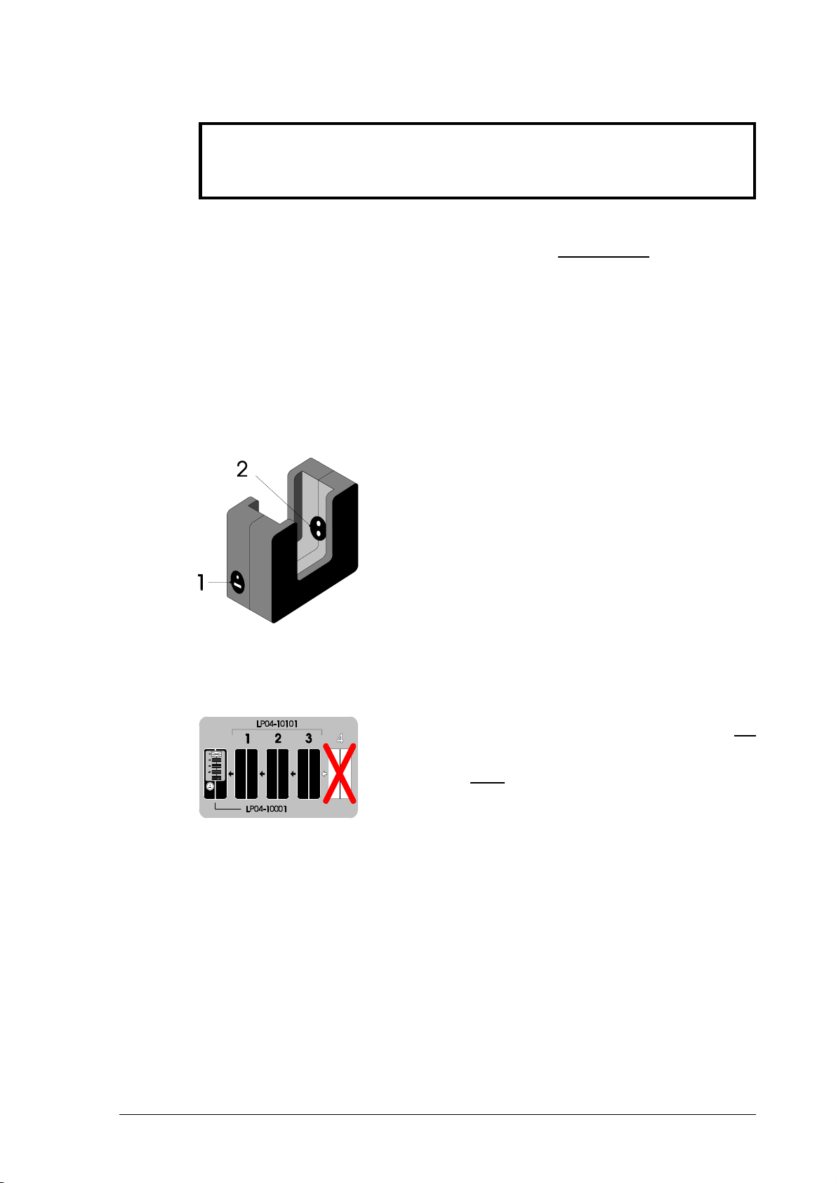
For charging you need the HS charging adapterHS charging adapter
HS charging adapterHS charging adapter
HS charging adapter (see illustration),
which can be used either in the workshop or in the standby vehicle.
The following items can be connected to
the side of the charging adapter:
l230 V mains power pack ≈,
l12 V= vehicle adapter,
l24 V= vehicle adapter.
A maximum of 3 charging adapters with no
socket can be connected to the charging
adapter with a socket.
The detector has a microprocessor-controlled heuristic operating-
hours account.
If the detector is not stored in the charging adapter the NiCd battery
will spontaneously discharge.
In order to verify the capacity of the NiCd battery we recommend
youtooperate thedetectoruntiltheundervoltage alarm istriggered
(the detector automatically switches off), then recharge it. The
available battery capacity is now determined.

14
ChargingCharging
ChargingCharging
Charging
Place the EX-TEC® SNOOPER H (switched off) in the charging
adapter. They are connected via the charging contacts (item 7) and
the adapter contacts (item 2 in the illustration on page 14). An
acoustic signal sounds to indicate the start of charging.
The charging period required is calculated from the operating
hours and a display of the following type appears:
lthe detector has 5 operating hours left (=
5 bars) and will take 3 hours to become
fully charged
lif it is fully charged all the bars are visible
and the number display disappears
lthe detector can be left in the charger
until it is next needed
Spontaneous dischargeSpontaneous discharge
Spontaneous dischargeSpontaneous discharge
Spontaneous discharge
If the detector is not connected to the charger when switched off,
the nickel-cadmium battery spontaneously discharges, thus
reducing the available operating hours.
☞Short periods of operation and prolonged disuseShort periods of operation and prolonged disuse
Short periods of operation and prolonged disuseShort periods of operation and prolonged disuse
Short periods of operation and prolonged disuse
may lead in the long term to the so-called "memorymay lead in the long term to the so-called "memory
may lead in the long term to the so-called "memorymay lead in the long term to the so-called "memory
may lead in the long term to the so-called "memory
effect", in which the display indicates a higher batteryeffect", in which the display indicates a higher battery
effect", in which the display indicates a higher batteryeffect", in which the display indicates a higher battery
effect", in which the display indicates a higher battery
capacity than is actually available.capacity than is actually available.
capacity than is actually available.capacity than is actually available.
capacity than is actually available.
This can be avoided by fully discharging the detectorThis can be avoided by fully discharging the detector
This can be avoided by fully discharging the detectorThis can be avoided by fully discharging the detector
This can be avoided by fully discharging the detector
regularly (e.g. once a month), leaving it switched onregularly (e.g. once a month), leaving it switched on
regularly (e.g. once a month), leaving it switched onregularly (e.g. once a month), leaving it switched on
regularly (e.g. once a month), leaving it switched on
until it automaticuntil it automatic
until it automaticuntil it automatic
until it automatically switches off, then recharging itally switches off, then recharging it
ally switches off, then recharging itally switches off, then recharging it
ally switches off, then recharging it !!
!!
!

15
4.04.0
4.04.0
4.0 Inspection, testing and maintenanceInspection, testing and maintenance
Inspection, testing and maintenanceInspection, testing and maintenance
Inspection, testing and maintenance
DVGW work sheet G 465/IV requires detectors to be inspected,
tested and maintained.
Sensitivity testingSensitivity testing
Sensitivity testingSensitivity testing
Sensitivity testing
may be necessary several times a day, according to G 465/I,
depending on the circumstances - particularly with gas detectors
used to monitor mains pipes.
InspectionInspection
InspectionInspection
Inspection
must be carried out up to six times a year, depending on frequency
of use - and at any rate at least once a year. The following items
must be tested:
ldetector condition lzero point
lbattery condition lsensitivity (with test gas)
lintake channel
TT
TT
Test reportest report
est reportest report
est report
Test results must be recorded. A specimen form will be found on
the last page of this manual.
Servicing and maintenanceServicing and maintenance
Servicing and maintenanceServicing and maintenance
Servicing and maintenance
DVGW work sheet G 465/IV specifies that servicing and
maintenance of the detectors may be carried out only by the
following persons:
lthe SEWERIN Service Department or
lan expert authorised by SEWERIN.
Servicing must be carried out at least once a year. The next
scheduled date must be entered on the inspection sticker attached
to the detector (month/year).
After servicing a certificate must be completed.

16
4.14.1
4.14.1
4.1 TT
TT
Test Setest Set
est Setest Set
est Set
The zero point and sensitivity should be tested with the SPESPE
SPESPE
SPE test
set and a suitable test gas:
Pos. 1
SPESPE
SPESPE
SPE test set, used to test:
lzero point
lsensitivity
and for use with the following test gases:
methane CH4:l1.00 vol.%
propane C3H8:l1.00 vol.%
For detector settings other than methane or propane the correct
values can be found inside the cover (on page 2).
Betriebsanleitung der
Geräte beachten!
Zur Überprüfung von
Gasmeßgeräten mit Pumpe
gemäß DVGW-Richtlinie
G 465/IV
3
1
2

17
4.24.2
4.24.2
4.2 Function testingFunction testing
Function testingFunction testing
Function testing
Proceed as follows:
●screw the test gas can onto the SPESPE
SPESPE
SPE test set as far as it will
go
●connect the test head of the SNOOPER HSNOOPER H
SNOOPER HSNOOPER H
SNOOPER H or SNOOPERSNOOPER
SNOOPERSNOOPER
SNOOPER
H smallH small
H smallH small
H small to the tester hose
lswitch the EX-TEC® SNOOPER H on and wait for a stable
zero point to be established (warm-up time)
lplace the test head on the detector's sensor head
lholddown the releasebuttononthe testeruntiltheindicated
concentration has reached a stable value
Admissible display values with :
ltest gas 1.00 vol.% methane CH4:0.80 ... 1.20 vol.%
ltest gas 1.00 vol.% propane C
3H8: 0.80 ... 1.20 vol.%
If display values are outside these tolerances the detector must
be recalibrated (section 5.0 Adjustment).

18
5.0 Adjustment
The EX-TEC® SNOOPER H is factory-set with test gas. You can
adjust the detector using an appropriate test gas.
To carry out the adjustment you need:
the EX-TEC® SNOOPER H,charged
the SPE test set
the SNOOPER H or SNOOPER H small test head
1.00 vol.% methane or propane test gas in synthetic air
the adjusting pin
Carry out the process exactly the same way as function-testing
(section 4.2).
☞For a successful adjustment both
steps (adjustment of the zero point and of
sensitivity ) must be carried out !
Switching on the adjustment mode
inserttheadjustingpinintheopeningon
the back of the detector (item 6)
press the service key behind it and
simultaneously push the on/off key
(item 1) upwards for approx. 2 seconds
Table of contents
Other sewerin Gas Detector manuals


Popular Gas Detector manuals by other brands


Navim Group Company
Navim Group Company EsiWelma Sensigas URS40SS manual

AGS
AGS Merlin User & installation manual

AIR SYSTEMS INTERNATIONAL
AIR SYSTEMS INTERNATIONAL CO-91 Series manual

Aereco
Aereco S-C02/T Installation and maintenance instruction

Tecnocontrol
Tecnocontrol SE182PM user manual

Delta
Delta DG510/CG manual

Emerson
Emerson Rosemount 925FGD quick start guide

S&S Northern
S&S Northern Merlin 1000BH Installation operation & maintenance

BOREAL LASER
BOREAL LASER GasFinder FCr Operation manual

Inficon
Inficon IRwin S quick start guide

MSA
MSA Ultima X operating manual

New Cosmos Electric
New Cosmos Electric KD-12 instruction manual