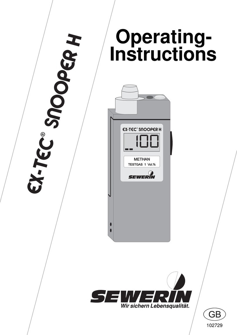
sewerin EX-TEC SR5 User manual

Instructions
Operating-
102424

Measurable success by Sewerin equipment
You settled on a precision instrument.
A good choice!
Our equipment stands out for guaranteed safety, optimal output and efficiency.
They correspond with the national and international guide-lines.
These operating instructions will help you to handle the instrument quickly and
competently.
Please pay close attention to our operating instructions before usage.
In case of further queries our staff is at your disposal at any time.
Yours
Hermann Sewerin GmbH
Robert-Bosch-Straße 3
D-33334 Gütersloh
: +49 - (0) - 52 41/9 34-0
FAX : +49 - (0) - 9 34-4 44
http:// www.sewerin.com

1
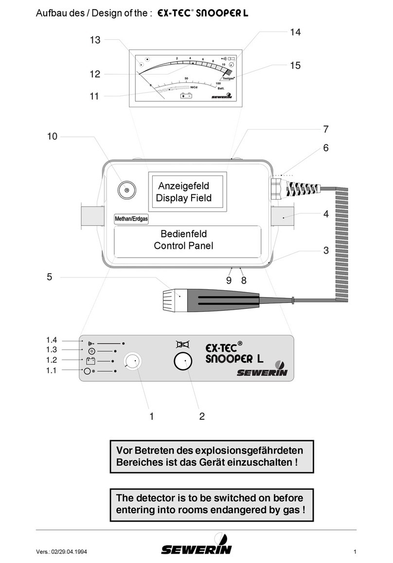
Design of the: EX-TEC® SR5
1
2
3
6
7
4
5

2
Notes

3
EX-TEC® SR 5, SR4, SR2
VARIOTEC® 8
Operating InstructionsOperating Instructions
Operating InstructionsOperating Instructions
Operating Instructions ................
................
........ pages 3 - 52pages 3 - 52
pages 3 - 52pages 3 - 52
pages 3 - 52
102424 - 04/20.08.1999

4
For your safety *For your safety *
For your safety *For your safety *
For your safety *
The law governing technical equipment (the Law on the afety of Appliances)
of 24.06.1968 (BGBl.I, page 717) as amended by the Amendment Law of
13.08.1979 (BGBl.I, page 1432) requires the following matters to be drawn
to your attention:
Comply with the Operating InstructionsComply with the Operating Instructions
Comply with the Operating InstructionsComply with the Operating Instructions
Comply with the Operating Instructions.
Before operating or adjusting the appliance you must be thoroughly familiar
with this operating manual. You must comply with it in every respect.
The appliance is designed only for the application described and for
industrial (commercial) use.
Liability for Function an /or DamageLiability for Function an /or Damage
Liability for Function an /or DamageLiability for Function an /or Damage
Liability for Function an /or Damage
Liability for the functioning of the appliance passes to the owner or operator
in all cases in which the appliance has been improperly maintained or
repaired by persons not associated with EWERIN ervice or if it has been
used for a purpose not in accordance with its designated application.
You should therefore always use original EWERIN accessories with the
EX-TEC® SR 5, SR4, SR2 and VARIOTEC® 8.
Hermann ewerin GmbH accepts no responsibility for damage due to a
failure to comply with the foregoing instructions. The guarantee and liability
terms of the Hermann ewerin GmbH terms of sale and supply are not
extended by the foregoing.
We reserve the right to make technical changes in the course of continued
development.
HERMANN EWERIN GMBH
* All references to laws, statutes and norms relate to the legislation of the Federal Republic of
Germany.

5
ContentsContents
ContentsContents
Contents pagepage
pagepage
page
For your safetyFor your safety
For your safetyFor your safety
For your safety ........................................................................................................................................................................
........................................................................................................................................................................
.................................................................................... 4 4
4 4
4
1.01.0
1.01.0
1.0 The EX-TEC® SR5, SR4, SR2 and VARIOTEC® 8
models ............. 6 6
6 6
6
1.1 Tests ............................................................................................. 8
1.2 Probe systems ............................................................................. 9
2.02.0
2.02.0
2.0 Measuring operationMeasuring operation
Measuring operationMeasuring operation
Measuring operation................................................................................................................................
................................................................................................................................
................................................................ 1 1
1 1
111
11
1
2.1 witching on ................................................................................ 11
2.2 Illumination and contrast ............................................................. 12
2.3 Pump operation .......................................................................... 13
2.4 Alarm signal and volume ............................................................ 14
2.5 Alarm threshold value ................................................................. 14
2.6 witching measuring ranges ...................................................... 15
2.7 Zero-point adjustment ................................................................ 16
2.8 Workplace monitoring ................................................................ 16
2.9 Battery alarm............................................................................... 18
2.10 witching off ............................................................................... 18
3.03.0
3.03.0
3.0 Charging techniqueCharging technique
Charging techniqueCharging technique
Charging technique..................................................................................................................................
..................................................................................................................................
................................................................. 19 19
19 19
19
4.04.0
4.04.0
4.0 Inspection, testing an maintenanceInspection, testing an maintenance
Inspection, testing an maintenanceInspection, testing an maintenance
Inspection, testing an maintenance........................................................................
........................................................................
.................................... 21 21
21 21
21
4.1 Test sets ..................................................................................... 22
4.2 Test gases .................................................................................. 24
4.3 Function testing .......................................................................... 25
5.05.0
5.05.0
5.0 A justmentA justment
A justmentA justment
A justment................................................................................................................................................................
................................................................................................................................................................
................................................................................ 26 26
26 26
26
6.06.0
6.06.0
6.0 TT
TT
Technical specificationsechnical specifications
echnical specificationsechnical specifications
echnical specifications..................................................................................................................
..................................................................................................................
......................................................... 34 34
34 34
34
7.07.0
7.07.0
7.0 TT
TT
Technical ataechnical ata
echnical ataechnical ata
echnical ata ....................................................................................................................................................
....................................................................................................................................................
.......................................................................... 37 37
37 37
37
8.08.0
8.08.0
8.0 AccessoriesAccessories
AccessoriesAccessories
Accessories............................................................................................................................................................
............................................................................................................................................................
.............................................................................. 39 39
39 39
39
9.09.0
9.09.0
9.0 Error messagesError messages
Error messagesError messages
Error messages ..............................................................................................................................................
..............................................................................................................................................
....................................................................... 40 40
40 40
40
10.010.0
10.010.0
10.0 Parts subject to wearParts subject to wear
Parts subject to wearParts subject to wear
Parts subject to wear ............................................................................................................................
............................................................................................................................
.............................................................. 42 42
42 42
42
EC-TEC-T
EC-TEC-T
EC-Type Examinations Certificateype Examinations Certificate
ype Examinations Certificateype Examinations Certificate
ype Examinations Certificate ....................................................................................................
....................................................................................................
.................................................. 43 43
43 43
43
Declarations of conformityDeclarations of conformity
Declarations of conformityDeclarations of conformity
Declarations of conformity ............................................................................................................................
............................................................................................................................
.............................................................. 47 47
47 47
47
TT
TT
Test reportsest reports
est reportsest reports
est reports................................................................................................................................................................................
................................................................................................................................................................................
........................................................................................ 51 51
51 51
51

6
1.01.0
1.01.0
1.0 The The
The The
The EX-TEC® SR5, SR4, SR2 and VARIOTEC® 8 mo elsmo els
mo elsmo els
mo els
This family of detectors consists of a total of four combined detectors
for the following uses:
EX-TEC® SR5 (Ex-protected)
•Gas etectionGas etection
Gas etectionGas etection
Gas etection
above-ground gas detection for
pipeline monitoring (ppm range)
•Interior installationsInterior installations
Interior installationsInterior installations
Interior installations
leak detection for pipelines in
buildings (ppm range)
•Workplace monitoringWorkplace monitoring
Workplace monitoringWorkplace monitoring
Workplace monitoring
monitoring proximity to the
Lower Explosive Limit (%LEL
range)
•LocationLocation
LocationLocation
Location
concentration measurement in
probe holes (vol.% range)
•Gasing an inertisationGasing an inertisation
Gasing an inertisationGasing an inertisation
Gasing an inertisation
concentration measurement in
pipelines (vol.% range)
EX-TEC® SR4 (Ex-protected)
•Workplace monitoringWorkplace monitoring
Workplace monitoringWorkplace monitoring
Workplace monitoring
monitoring proximity to the
Lower Explosive Limit (%LEL
range)
•LocationLocation
LocationLocation
Location
concentration measurement in
probe holes (vol.% range)
•Gasing an inertisationGasing an inertisation
Gasing an inertisationGasing an inertisation
Gasing an inertisation
concentration measurement in
pipelines (vol.% range)

7
EX-TEC® SR2 (Ex-protected)
•LocationLocation
LocationLocation
Location
concentration measurement in
probe holes (vol.% range)
•Gasing an inertisationGasing an inertisation
Gasing an inertisationGasing an inertisation
Gasing an inertisation
concentration measurement in
pipelines (vol.% range)
VARIOTEC® 8
•Gas etectionGas etection
Gas etectionGas etection
Gas etection
above-ground gas detection for
pipeline monitoring (ppm range)
•LocationLocation
LocationLocation
Location
concentration measurement in
probe holes (vol.% range)

8
1.11.1
1.11.1
1.1 TT
TT
Testsests
estsests
ests
Passive explosion protectionPassive explosion protection
Passive explosion protectionPassive explosion protection
Passive explosion protection
The EX-TEC® SR5, EX-TEC® SR4 and EX-TEC® SR2 models are explosion-
proof in accordance with European norms (CENELEC):
EC prototype test certificate: PTB 96 ATEX 2166
Classification: II 2 G EEx ib d IIB T4
Test institute: Physikalische-Technische
Bundesanstalt, Braunschweig
Active explosion protectionActive explosion protection
Active explosion protectionActive explosion protection
Active explosion protection
The EX-TEC® SR5 and EX-TEC® SR4 have also been tested for
functional safety in the Workplace Monitoring (WPM) field:
Test report: PFG no. 41300897
Test institute: DMT-Gesellschaft für Forschung
und Prüfung mbH, Essen
The test certificates can be found on and after page 43.

9
1.21.2
1.21.2
1.2 Probe systemsProbe systems
Probe systemsProbe systems
Probe systems
- Probes for the survey of gas istributions networks -- Probes for the survey of gas istributions networks -
- Probes for the survey of gas istributions networks -- Probes for the survey of gas istributions networks -
- Probes for the survey of gas istributions networks -
Carpet probeCarpet probe
Carpet probeCarpet probe
Carpet probe
for checking stable surfaces.
The sample is drawn into an
excrescence in a neoprene mat
in contact with the surface with no
extraneous emissions.
Bell probe,Bell probe,
Bell probe,Bell probe,
Bell probe,
telescopic bell probetelescopic bell probe
telescopic bell probetelescopic bell probe
telescopic bell probe
for checking unstable and
overgrown surfaces.
It can be used in confined
spaces, e.g. between parked
cars or in front gardens.
- Probes for localisation -- Probes for localisation -
- Probes for localisation -- Probes for localisation -
- Probes for localisation -
Search probeSearch probe
Search probeSearch probe
Search probe
for measuring concentrations in
probe holes,
with a rigid rubber cone to seal
off the probe hole,
2 different probe tips (length 245
mm or 345 mm),
carbon-dioxide filter to filter out
traces of CO2

10
- Probes for hollow spaces -- Probes for hollow spaces -
- Probes for hollow spaces -- Probes for hollow spaces -
- Probes for hollow spaces -
Floating probeFloating probe
Floating probeFloating probe
Floating probe
for measuring concentrations in
pits,
with suction vent and hose
connection
Divisible han probeDivisible han probe
Divisible han probeDivisible han probe
Divisible han probe
for the detection of leaks in pipes
installed in poorly accessible places,
measuring of concentration in con-
tainers, overall length 900 mm
- Probes for house service lines -- Probes for house service lines -
- Probes for house service lines -- Probes for house service lines -
- Probes for house service lines -
Flexible han probesFlexible han probes
Flexible han probesFlexible han probes
Flexible han probes
for the detection of leaks in
house service lines, handle with
flexible swan neck and probe
hose, overall lengths 360 mm or
660 mm
☞Except with the carpet probe , a probe hoseExcept with the carpet probe , a probe hose
Except with the carpet probe , a probe hoseExcept with the carpet probe , a probe hose
Except with the carpet probe , a probe hose
shoul always be use shoul always be use
shoul always be use shoul always be use
shoul always be use withwith
withwith
with a hy rophobic filter ! a hy rophobic filter !
a hy rophobic filter ! a hy rophobic filter !
a hy rophobic filter !

11
2.02.0
2.02.0
2.0 Measuring operationMeasuring operation
Measuring operationMeasuring operation
Measuring operation
☞Please fol out the illustration insi e thePlease fol out the illustration insi e the
Please fol out the illustration insi e thePlease fol out the illustration insi e the
Please fol out the illustration insi e the
front cover !front cover !
front cover !front cover !
front cover !
ItemItem
ItemItem
Item DescriptionDescription
DescriptionDescription
Description FunctionFunction
FunctionFunction
Function
1 alarm lamp optical warning
when alarm thresholds are
exceeded
2 LCD display display of gas
concentrations and
operating conditions
3 probe connection connection to the probes
described
4 buttonboard operating the detector
5 harness for portable systems
6 outlet for gas sample
7 buzzer acoustic warning
when alarm thresholds are
exceeded
2.12.1
2.12.1
2.1 Switching onSwitching on
Switching onSwitching on
Switching on
•press the on/off buttonon/off button
on/off buttonon/off button
on/off button (gas-
detection mode) or WPM button WPM button
WPM button WPM button
WPM button
(workplace-monitoring mode, p.
16 ff.) for approx. 2 seconds
•optical and acoustic control signal
(items 1 and 7) operate for approx.
2 seconds

12
•display of available operating
hours in the form of bars (e.g. 5
hours)
•the integral pump operates at
maximum power
•wait until the zero point has
established itself in fresh air
(approx. 2-3 minutes):
EX-TEC® SR5 and VARIOTEC® 8:
☞0 PPM0 PPM
0 PPM0 PPM
0 PPM
(after flashing stops)
EX-TEC® SR4 and EX-TEC® SR2:
☞0,0 %VOL0,0 %VOL
0,0 %VOL0,0 %VOL
0,0 %VOL
2.22.2
2.22.2
2.2 Illumination an contrastIllumination an contrast
Illumination an contrastIllumination an contrast
Illumination an contrast
•pressing the light buttonlight button
light buttonlight button
light button
switches the LCD illumination on
and off
•the illumination automatically
switches off approx. 4 minutes
after being switched on
•simultaneously pressing the light
button anan
anan
an a cursor button
increases or reduces the contrast
of the LCD display

13
2.32.3
2.32.3
2.3 Pump operationPump operation
Pump operationPump operation
Pump operation
•pressing the pump buttonpump button
pump buttonpump button
pump button
switches the pump on and off
•the corresponding symbol
appears in or disappears from
the LCD display (item 2)
•this enables the pump function to
be checked
☞Altering the pump powerAltering the pump power
Altering the pump powerAltering the pump power
Altering the pump power
(available only on the (available only on the
(available only on the (available only on the
(available only on the EX-TEC® SR5) !) !
) !) !
) !
•simultaneously pressing the
pump button anan
anan
an one cursor
button increases or reduces the
pump power
☞gas etectiongas etection
gas etectiongas etection
gas etection
for above-ground gas detection
(pipeline monitoring) always use
maximum pump powermaximum pump power
maximum pump powermaximum pump power
maximum pump power
☞house service lineshouse service lines
house service lineshouse service lines
house service lines
for detecting leaks in pipelines
inside buildings always use
minimum pump powerminimum pump power
minimum pump powerminimum pump power
minimum pump power

14
2.42.4
2.42.4
2.4 Alarm signal an volumeAlarm signal an volume
Alarm signal an volumeAlarm signal an volume
Alarm signal an volume
•pressing the signal buttonsignal button
signal buttonsignal button
signal button
switches the alarm signal on and
off
•the corresponding symbol
appears in or disappears from
the LCD display (item 2)
•this enables the alarm signal to
be checked
•simultaneously pressing the
signal button anan
anan
an one cursor
button increases or reduces the
buzzer volume (item 7)
2.52.5
2.52.5
2.5 Alarm threshol valueAlarm threshol value
Alarm threshol valueAlarm threshol value
Alarm threshol value
•when the threshol valuethreshol value
threshol valuethreshol value
threshol value
buttonbutton
buttonbutton
button is held down
•the alarm threshold value (e.g. 10
PPM) flashes in the full-range
display

15
•holding down the threshold value
button anan
anan
an repeatedly pressing
one cursor button increases or
reduces the alarm threshold value
•this value is preserved even when
the detector is switched off
2.62.6
2.62.6
2.6 Switching measuring rangesSwitching measuring ranges
Switching measuring rangesSwitching measuring ranges
Switching measuring ranges
•all detectors have an analogueanalogue
analogueanalogue
analogue
isplayisplay
isplayisplay
isplay (above, full range) anan
anan
an a
igital isplayigital isplay
igital isplayigital isplay
igital isplay (below);
both scales indicate the same
concentration (e.g. 70 PPM)
•the full rangefull range
full rangefull range
full range is a logarithmic
scale covering the range:
0 PPM ... 100 %VOL
•here the display of low
concentrations is intensified;
the measurement result can be
read off from the digital display
•repeatedly pressing the zoomzoom
zoomzoom
zoom
buttonbutton
buttonbutton
button switches between the fullfull
fullfull
full
and optimum rangesoptimum ranges
optimum rangesoptimum ranges
optimum ranges
•depending on the concentration,
switching between the following
measurement ranges is
automatic:automatic:
automatic:automatic:
automatic:
0 ... 10 PPM 0 ... 1 %VOL
0 ... 100 PPM 0 ... 10 %VOL
0 ... 1,000 PPM 0 ... 100 %VOL
•the optimum measurement range
in this example is 0 ... 100 PPM

16
•repeatedly pressing one of the
cursor buttons while holding down
the zoom button switches
manually to the required display
range
2.72.7
2.72.7
2.7 Zero-point a justmentZero-point a justment
Zero-point a justmentZero-point a justment
Zero-point a justment
•if the detector fails to reach its
zero point of
0 PPM0 PPM
0 PPM0 PPM
0 PPM or 0,00,0
0,00,0
0,0 %VOL%VOL
%VOL%VOL
%VOL
after flushing with copious fresh
air, pressing the zero pointzero point
zero pointzero point
zero point
buttonbutton
buttonbutton
button enables you to adjust it
manually
•the reading display flashes while
the adjustment is being carried
out
•measurement cannot be
resumed until afteafte
afteafte
after the flashing
stops
2.82.8
2.82.8
2.8 Workplace monitoringWorkplace monitoring
Workplace monitoringWorkplace monitoring
Workplace monitoring
☞This function is available only with the This function is available only with the
This function is available only with the This function is available only with the
This function is available only with the EX-TEC® SR5
an an
an an
an EX-TEC® SR4 etectors ! etectors !
etectors ! etectors !
etectors !
•this function is switched on by
pressing the WPM WPM
WPM WPM
WPM (ww
ww
workpp
pp
place
mm
mm
monitoring) buttonbutton
buttonbutton
button
•the detector can also be switched
on by pressing this button

17
•this measuring range is used to
monitor proximity to the LELLEL
LELLEL
LEL
(ll
ll
lower ee
ee
explosion
ll
ll
limit)
•after approx. 8 seconds' warm-
up time a stable zero point is
reached
•the pump runs at minimum power
and the acoustic operating signal
(item 7) sounds every 5 seconds
•when the pre-set threshold of
20 %LEL is exceeded
methane:methane:
methane:methane:
methane: 20 %LEL = 0,88 %VOL
(display = 0,90 %VOL)
propane:propane:
propane:propane:
propane: 20 %LEL = 0,34 %VOL
the a vance alarma vance alarm
a vance alarma vance alarm
a vance alarm is triggered
both optically (item 1) and
acoustically (item 7)
•the advance alarm is an
intermittent tone quite distinct
from the operating signal;
it ceases after a certain perioceases after a certain perio
ceases after a certain perioceases after a certain perio
ceases after a certain perio
and cannot be cleared
•if the concentration exceeds
100 %LEL
methane:methane:
methane:methane:
methane:100 %LEL = 4,40 %VOL
propane:propane:
propane:propane:
propane:100 %LEL = 1,70 %VOL
the main alarmmain alarm
main alarmmain alarm
main alarm is triggered
optically (item 1) and acoustically
(item 7)

18
•the main alarm is a continuous
tone quite distinct from the
operating signal;
it continues in efinitelycontinues in efinitely
continues in efinitelycontinues in efinitely
continues in efinitely and
cannot be cleared
•Cancelling the main alarm:Cancelling the main alarm:
Cancelling the main alarm:Cancelling the main alarm:
Cancelling the main alarm:
switch to location operation (press
the pump button for approx. 2
seconds ) or switch the detector
off
2.92.9
2.92.9
2.9 Battery alarmBattery alarm
Battery alarmBattery alarm
Battery alarm
•if the battery symbol appears in
the LCD display, at least 15
minutes' operating time remains;
after that the detector must be
recharged
•in workplace-monitoring mode
the battery alarm is accompanied
by a "double beep" to distinguish
it from the operating signal
2.10Switching off2.10Switching off
2.10Switching off2.10Switching off
2.10Switching off
•Press the on/off buttonon/off button
on/off buttonon/off button
on/off button for
approx. 2 seconds
•the optical and acoustic
monitoring signals (items 1 and
7) operate for approx. 2 seconds
•remaining operating hours are
displayed in the form of bars
This manual suits for next models
3
Table of contents
Other sewerin Gas Detector manuals
