manuals.online logo
Brands
  1. Home
  2. •
  3. Brands
  4. •
  5. Medem
  6. •
  7. Gas Detector
  8. •
  9. Medem AGDS-MC v2 User manual

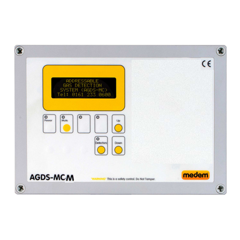
Medem AGDS-MC v2 User manual

00250
AGDS-MC v2
• Gas Detection . (Up to 16 detectors, with power pack)
• Natural gas, LPG, carbon onoxide & carbon dioxide
• Re ote e ergency stops
• Fire Alar input onitoring
• BMS relay (Settable)
• 5 year warranty - 10 years when co issioned
AGDS-MC features
Installation Instructions
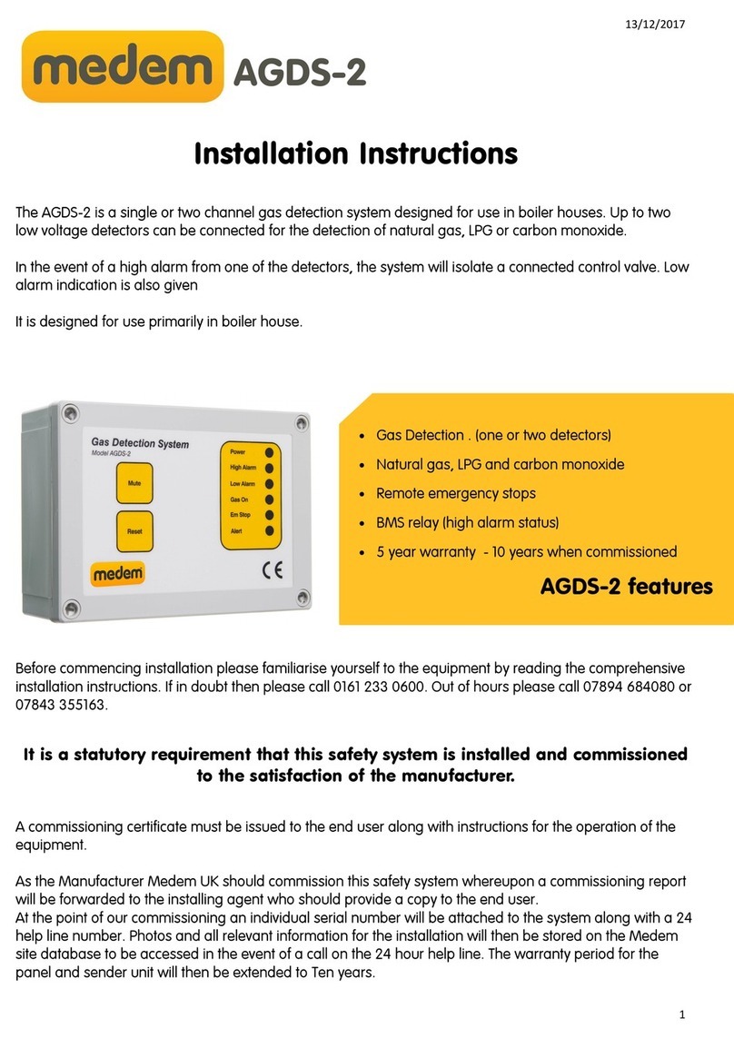
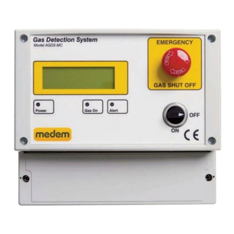
The AGDS-MC v2 is a ulti channel gas detection syste designed for use in boiler houses. Six low voltage
detectors can be connected ( 16 with a power pack) for the detection of natural gas, LPG, or carbon
onoxide, carbon dioxide and oxygen depletion.
In the event of a high alar fro one of the detectors, the syste will isolate a connected control valve. Low
alar indication is also given.
Even with the syste switched off It can still be used to onitor for carbon onoxide and dioxide via its 0-
10v output and BMS relays. Should there be an issue fro a solid fuel appliance it can raise an alar or
switch ventilation on via a relay.
Before co encing installation please fa iliarise yourself to the equip ent by reading the co prehensive
installation instructions. If in doubt then please call 0161 233 0600. Out of hours please call 07894 684080 or
07843 355163.
It is a statutory requirement that this safety system is installed and commissioned
to the satisfaction of the manufacturer.
A co issioning certificate ust be issued to the end user along with instructions for the operation of the
equip ent.
As the Manufacturer, Mede UK should co ission this safety syste whereupon a co issioning report
will be forwarded to the installing agent who should provide a copy to the end user.
At the point of our co issioning an individual serial nu ber will be attached to the syste along with a 24
help line nu ber. Photos and all relevant infor ation for the installation will then be stored on the Mede
site database to be accessed in the event of a call on the 24 hour help line. The warranty period for the pan-
el and sender unit will then be extended to Ten years.
2
00250
Syste description
AGDS-MC v2
The AGDS-MC is a gas detection syste designed to onitor the at osphere for target gases.
The syste co prises of a ains powered panel capable of operating up to six co bustible and two carbon onoxide
detectors (or 16 total in conjunction with the AD-PP transfor er pack),. Co bustible, Carbon Monoxide, Carbon Dioxide &
Oxygen are available.
The detectors are pre-calibrated by Mede (UK) Ltd such that they only require to be connected to the panel and functionally
tested.
In the event of a high alar fro one of the detectors the syste will isolate the gas supply by closing a connected electric
control valve. E ergency stop buttons and Ther al Links can be fitted and a fire alar can close the gas valve when connected
to the panel.
Control Panel
Lo Voltage Gas Detectors
Co bustible detectors are set to alar at 5% LEL (pre alar ) and 10% LEL for the high alar .
Carbon Monoxide detectors are set to alar at 20pp (pre alar ) and 30pp for high alar .
Carbon Dioxide detectors have settable high alar s of 1500, 2200, 4000, & 5000 PPM’s
Oxygen depletion detectors are set to alar at 19.5% (pre alar and 18% (high alar )
Connect a detector to the “detectors ter inals” (11&12), each detector has a rotary address selector switch (0-F) set to a unique
address. Once connected and addressed you are required to press the “learn Field Devices” button (21).
Each gas sensor unit has an LED which shows green when power is applied.
Note: There is a war up period after initial power up of approxi ately 90 seconds. During this ti e the green LED will flash once
per second and the output signal will be inhibited. This is to prevent spurious alar s. After the war up period and on application
of gas, the red LED will light when a high gas alar level is reached.
Emergency Stop button
OLED Screen for clear
Gas On/Off
Switch on to open gas valve
3
00250
Main features
Connections to panel: arked on board
1. Earth connection ter inals.
2. Live & Neutral 230 volts supply fro 3a p switched fuse spur.
3. 230 volts out to gas solenoid valve.
4. To contactor for isolating socket electricity supply, or fan (optional).
5. Mains rated BMS relay set using switch 18.
6. Mains rated BMS relay set using switch 17.
7. Re ote e ergency stop and ther al links, SELV, connect in series ultiple buttons (requires a N/C circuit).
8. Extract fan interlock for current onitor (CM2M-K) or PD switches.
9. Supply fan interlock for current onitor (CM2M-K) or PD switches.
10. 12 volt power for current onitor (CM2M-K).
11. Power connections for detectors, Methane, LPG, CO, CO2, Oxygen, Te perature.
12. Co s connections for detectors, Methane, LPG, CO, CO2, Oxygen, Te perature.
13. Fire alar input signal (N/C contact required).
14. 0-10 volt output to fan speed controllers based on CO2 and te perature levels.
15. SELV Output for low power beacons/toners. Set using switch 26.
16. Enable/Disable internal toner.
17. BMS relays settings for relays AUX 1 (5) and (A) See page 6.
18. BMS relays settings for relays AUX 2 (6) and (B) See page 6.
19. See page 7.
20. Fan co button, enables co issioning of the gas supply without fans running.
21. Learn field device button, press once only when all detectors are connected and powered (verify with detectors button).
22. Lift Valve - will power open the gas valve (2) while the button is held down.
23. CO2 alar level adjust ent depending on application. Factory set for odel & use.
24. Ti er adjust ent for fan co issioning, allows ti ed period for gas installation co issioning.
25. See page 7.
26. Setting for VBMS (15). See page 6.
27. See page 7.
28. See page 7.
29. OPTFAN Enable/Disable the front panel “FANS” LED (switch on to disable).
24
23
1
4 2 3 5 7
6 8 11
9 10 13 12 14
16
18
17
19 26 25
28 27
29
20 21 22
15
See page 6 for settings
AGDS-MC v2
4
00250
Addressable Gas
detector
Address
And then press Learn
(21)
Wire ultiple detectors
in parallel
Earth Connections not sho n
1
4 2 3 5 7
6 8 11
9 10 13 12 14
17
15
Sche atic
AGDS-MC v2
230v Supply
3A p Fused Spur
Gas Solenoid
EM Stop Buttons,
Ther al links
(Nor ally closed)
For ultiple, connect in
series.
AUX 1 & AUX 2
Mains Rated
Potential free contact,
Max load 5a p’s
(latching relay)
See page 6
Basic connections
All current wiring regulations ust be followed with reference to running low and ains voltage cables together.
The axi u cable length between a detector and the control panel should not exceed 100 etres, whilst we would
always reco end using screen cable if the distance between the ain panel and the detectors is greater than 20 etres a
1 screened cable ust be used on the +VE, 0v ter inals
Gas detectors, require a four core screened Belden type security cable or 600v rated BMS cable ( ax cable length of
100 eters.)
Re ote e ergency stops and ther al links require a two core screened cable.
Warranty will be void if Fire Protection Cable or cable over 1 dia. is used on the SELV side.
(8,9)
Optional Ventilation
Interlock connections
(13)
Fire alar connection
Requires a N/C contact
in the fire panel
18
Optional
Switchable contact for
controlling an electrical
contactor etc
0 to 10v output for connection
to a fan speed controller
For use in conjunction with
Co2 detection
No inal 20v supply
Set using DIP switch
V BMS (26)
See page 6 for settings
5
00250
AGDS-MC v2 Re ote stop buttons
To EM Stop connections in the
panel
Use ter inals TB2 A & C Use ter inals TB2 A & C
Re ote stop buttons can be connected to the panel ter inal
arked as “EM STOP” (nu ber 7 ).
The re ote buttons ust be wired as shown in order to provide a
“closed contact” for the control panel.
If thermal links are to be installed these should be ired
in series ith the EM stop buttons
To EM Stop connections in the
panel
Indicator bar shows when
pressed
Nor al EM-Stop Activated
Multiple Stop Buttons
Single Stop Buttons
Resetting (indicator bar)
The stop buttons supplied by Mede are of a “Push Glass, key resettable” style, when activated a yellow indicator bar will
show and the unit will require resetting using the key provided.
Multiple stop buttons are wired in series.
If ther al links are to be installed these too should
be wired in series with the EM stop buttons
Use ter inal TB2 A & C
6
00250
1 2 3 4
Unused OFF OFF OFF OFF
Unused ON OFF OFF OFF
Unused OFF ON OFF OFF
Fan Fault - FF ON ON OFF OFF
EM Stop - ES OFF OFF ON OFF
Fire Panel Active -FA ON OFF ON OFF
High Alar (Any State) - HA OFF ON ON OFF
Low Alar (Any State) - LA ON ON ON OFF
Gas On State OFF OFF OFF ON
Detector Fault ON OFF OFF ON
Generic Fault (FF,ES,FA,HA OFF ON OFF ON
Key Switch State ON ON OFF ON
There are five relays on the syste which can be used for connecting to a BMS or sounder/Beacon etc., these
can be set for switching to various conditions using the table below. There are two ains rated (AUX) and three
SELV (BMS)
Two Mains rated (230v 5a ps)
Three SELV relays. (48 volts 1 a p)
AUX 1 and BMS A: are set using switch 17
AUX 2 and BMS B: are set using switch 18
BMS C: Fixed condition, changes state on Gas Switch On/Off only.
Settable conditions via dip switches (One condition selectable for each pair of relays)
BMS Relay Mains & SELV PCB
Syste Settings
AGDS-MC v2
18
17
5 6
7
00250
Option Switches
AGDS-MC v2
15 & 26 V BMS
Ter inal (15) VBMS is a no inal 20v output for use with external beacons, sounders etc.
The output can be switched fro 0 to +VE dependant on the setting of DIP switch (26)
DIP switch options and setting are as per the table above
Option s itch settings 19, 25, 27 & 28
There are various option switches available on the syste for acco odating so e of the ore co on
situations
There always needs to be careful consideration to risk when changing any of the default settings, Mede (UK)
Ltd would always reco end an onsite risk assess ent be carried out before any changes are i ple ented.
28
OPT A Spare
OPT B Auto restart on power failure and fire alar (off by default)
2MAR
Two inute delay to the auto restart - allows downstrea appliances fla e failure
devices to close
OPTX Spare
27
OP C Disables isolating gas on CO2 high alar . CM & CO still isolate as nor al
OP D
OP E Changes detector ti e to isolate fro 5s to 45s for CM & CO
OP F Changes CO alar levels fro 20 & 30 PPM to 80 & 100PPM
19
OPT G Fan run ti e using "FRUN" button
OPT H Spare
OPT I Allows BMS relays to indicate gas detector status when ain "Gas On" switch is off
OPT J Spare
25
OP K Spare
OP L Spare
OP M Spare
OP N Spare
8
00250
Gas Detection
Gas Detectors
IMPORTANT - Gas Detectors should not be installed until all building, construction or painting work etc.. Is co pleted, as these
works can effect the sensitivity and longevity of the detectors.
Ensure that the protective cover labels (RED) are re oved only
after the co pletion of all building work and the syste has
been co issioned by the Mede engineer.
The labels are required to be re oved for the detectors to
operate, but re oval before the co pletion of works risks
conta inating the sensor ele ent.
The syste is capable of operating a ix of up to 16 detectors (additional power pack ay be required) of different types.
The detector types are:
• Carbon Monoxide.
• Carbon Dioxide.
• Co bustible gases (Methane, Propane).
• Oxygen.
Detector location will vary dependant on the individual characteristics of the target gas that is being onitored for. See the gas
detectors own instructions for ore guidance.
+VE supply & Co ’s
Fro either the ain panel
Address Selector
Each detector ust be set to its own
address.
And then “learnt” using button (21)
Connection and addressing
Status LED
All current wiring regulations ust be followed with reference to running low and ains voltage cables together.
The axi u cable length between a detector and the control panel should not exceed 100 etres, if the distance between
the ain panel and the detectors is greater than 20 etres a 1 screened cable ust be used on the +VE, 0v ter inals
Gas detectors, require a four core screened Belden type security cable or 600v rated BMS cable ( ax cable length of
100 eters.)
Re ote e ergency stops and ther al links require a two core screened cable.
Warranty will be void if Fire Protection Cable or cable over 1 dia. is used on the SELV side.
When addressing gas detectors CO &
CO2 detectors ust be nu bered
before co bustible gas detectors.
Detector Infor ation
AGDS-MC v2
9
00250
Detector Infor ation
AGDS-MC v2
Detector location will vary dependant on the individual characteristics of the target gas that is being onitored for.
The descriptions below describe the position for each detector after considering these characteristics.
For proper function care ust be taken not to site a detector in a “dead space” or in the flow of any ventilation.
Natural Gas/Methane
Natural gas detectors should be ounted at high level on a wall approxi ately 150 fro the ceiling height and avoiding
corners and potential dead air areas.
Natural gas detectors should not be ounted below the height of the top of a doorway for exa ple. This is because as the gas
is slightly lighter than air it will rise filling the roo fro the ceiling down and will spill through the top of a door opening into the
next roo . If the detectors are ounted below this height then it will take longer the gas to reach the detector.
LPG /Propane
LPG gas is heavier than air so detectors need to be ounted at low level 100 fro the floor, consideration should be given
to any potential opping or wet floor height.
Carbon Monoxide
Carbon Monoxide is si ilarly weighted to air so detectors should be ounted between 1 to 2 eters fro the floor.
Carbon Dioxide
Carbon Dioxide detectors should be installed so they onitor the general level of CO2 within the area. They should be ounted
above standing head height and between 1 and 3 fro the potential source. Care should be taken so they are not located
close to the edge of a canopy or in direct flow of the supply or extract ventilation.
For additional infor ation or guidance on site specific require ents please don’t hesitate to contact us.
Each detector has its own Bi-Colour LED which is used to indicate the status of that detector.
Not Lit: No power/co ’s. These a four wire units and all connections are required, check the polarity of both the
power and the co ’s (MA/MB) ter inals are correct. Check the detector is address to the correct channel
and the detector has been learnt using (21)
Flashing Green: Detector is war ing up, the detectors will flash green on power up for 90 seconds while the sensor
ele ents stabilize. The syste will ignore any detectors while flashing.
Solid Green: Detector is powered and active.
Flashing Red: Low level alar . All detectors have both a low and high level alar , low level alar s serve as a warning
that an unsafe condition aybe building and gives chance to intervene before loss of gas service.
Solid Red High level alar . An unsafe level of the target gas have been reached and the syste will isolate the
gas supply. The cause of the alar will require identifying and resolving before the gas supply can be re-
established.
After installation a si ple bu p test can be perfor ed by using an appropriate level test gas in order to check operation. Full testing and
calibration checking takes place during a Mede co issioning.
Detector Location information
Detector Indications
10
00250
Warranty
AGDS-MC v2
Mede (UK) Li ited
Project House
19 Dalli ore Road
Manchester
M23 9NX
Tel: (0) 161 233 0600
Fax: (0) 161 233 0601
Web: www. ede .co.uk
E- ail: sales@ ede .co.uk
Mede UK Warranty
Ter s & Conditions
1. The warranty is a parts warranty and Mede UK Ltd will not cover or accept any labour or
other expenses that ay be incurred in the process of changing faulty product.
2. All panels and sender units are covered by a five year warranty.
3. Gas detector units and other re ote detectors carry a two year warranty. Installation of the
detectors should not be undertaken until all building and construction work is co pleted.
4. Gas solenoid valves carry the original anufacturers warranty, though as the supplier
Mede UK will exchange faulty valves for return to the anufacturer.
5. Where a Mede UK engineer (or another co pany appointed by Mede UK) co ission
and installed syste then that syste will carry a ten year warranty. This applies to the
ain panel and the sender unit. At the ti e of co issioning a security label with a serial
nu ber will be attached to the ain panel box. photographs and a co prehensive record
of the installation will be held by Mede UK.
6. Where a warranty clai is ade then, where appropriate, a written order to attend site
ust be provided to Mede UK A cost for labour and travel to site will be prepared as a
quote. The cost ust be included in the order.
7. Where it is found that the installation and/or the quality of work anship has contributed to
or wholly caused the failure of the product then we reserve the right to charge the whole or
a proportion of the cost of the faulty ite .
11
00250
Checklist
AGDS-MC v2
It is essential that the installation is carried out in the order given
below to ensure the correct operation of the syste .
First read the syste description sheet before following the
instructions below

1. Connect the Control valve twin & earth to the arked ter inals.
2. Connect BMS, beacons, sounders etc to the relay outputs.
3. Connect any additional EM stop buttons and ther al links in series to the ter inals arked “e stop”
4. Each detector has a blue rotary selector switch and each switch should be set to a different nu ber or letter starting with
“0”. Then connect the gas detectors to ter inals arked “detectors” (11,12) on the panel. Detectors can be wired “Daisy
chain”.
5. Connect the 3 a p fused spur 240 volt supply to arked ter inals (2).
6. Once power is connected to the panel the detectors will flash the green LEDs for 90 seconds after which the LEDs will be on
continuously.
7. Press the “learn field button” this is on the ain circuit board (no 21). Pressing this once allows the panel to learn how any
and which type of detectors are fitted.
8. Press the “Detectors” button on the front panel and check on the display that all the detectors have been recognised by the
syste . A recognised detector will appear as “CMOX”, “CDOX”, “CMBS” or “OXYG” with the detector reading now to it. Use
the UP and Down buttons to page through the detector listing to check all addresses. Note that a detector set at 0 appears

as 1 on the LCD and a detector set as 1 appears as 2 on the LCD etc.
9. At this point turn the on/off switch to the on position and panel will open the gas valve.
10. A functionality test of the detectors can be carried out by applying a s all a ount of target gas to the detectors. The
detector LED will turn red and the panel will alar and close the valve.
Please do not hesitate to call for advice on the
follo ing numbers:
0161 233 0600 office hours
Or out of hours call: 07843 355163 UK only
Notes.
It is reco ended that all syste s are co issioned after installation by Mede UK. This will extend the warranty period fro 5
years to 10 years and ensure the syste is working as designed.
Please see warranty conditions that ca e with the ain panel

Other Medem Gas Detector manuals

Medem SafeAir User manual

Medem

Medem SafeAir User manual

Medem AGDS-V User manual

Medem

Medem AGDS-V User manual

Medem SEC-B User manual

Medem

Medem SEC-B User manual

Medem SafeAir User manual

Medem

Medem SafeAir User manual

Medem AGDS-MC User manual

Medem

Medem AGDS-MC User manual

Medem SEC-K V4 User manual

Medem

Medem SEC-K V4 User manual

Medem AGDS-2em v2 User manual

Medem

Medem AGDS-2em v2 User manual

Medem SafeAir CM User manual

Medem

Medem SafeAir CM User manual

Medem AGDS-2em User manual

Medem

Medem AGDS-2em User manual

Medem AGDS-2 User manual

Medem

Medem AGDS-2 User manual

Medem AGDS-MCM v2 User manual

Medem

Medem AGDS-MCM v2 User manual

Medem AGDS-4 User manual

Medem

Medem AGDS-4 User manual

Medem AGDS-2em User manual

Medem

Medem AGDS-2em User manual

Medem SEC-L v4 User manual

Medem

Medem SEC-L v4 User manual

Medem AGDS-M User manual

Medem

Medem AGDS-M User manual

Popular Gas Detector manuals by other brands

Bacharach MVR-300 user manual

Bacharach

Bacharach MVR-300 user manual

RKI Instruments M2A Operator's manual

RKI Instruments

RKI Instruments M2A Operator's manual

FORENSICS DETECTORS FD-VAPE-WALL user manual

FORENSICS DETECTORS

FORENSICS DETECTORS FD-VAPE-WALL user manual

GEV FMG 1282 user manual

GEV

GEV FMG 1282 user manual

Riken Keiki SD-1DOX operating manual

Riken Keiki

Riken Keiki SD-1DOX operating manual

olympia electronics BS-685 quick start guide

olympia electronics

olympia electronics BS-685 quick start guide

Riken Keiki RX-515 operating manual

Riken Keiki

Riken Keiki RX-515 operating manual

Bühler technologies GAS 222.21 AMEX Brief instructions

Bühler technologies

Bühler technologies GAS 222.21 AMEX Brief instructions

Emerson Rosemount 936 Reference manual

Emerson

Emerson Rosemount 936 Reference manual

RKI GX-6000 Operator's manual

RKI

RKI GX-6000 Operator's manual

RKI Instruments GX-3R Pro Operator's manual

RKI Instruments

RKI Instruments GX-3R Pro Operator's manual

Smartwares RM400 user manual

Smartwares

Smartwares RM400 user manual

ZyAura ZG906CMONP operating instructions

ZyAura

ZyAura ZG906CMONP operating instructions

GasTech GTF220 manual

GasTech

GasTech GTF220 manual

Geca SE330K user manual

Geca

Geca SE330K user manual

Oldham OLCT 20 user manual

Oldham

Oldham OLCT 20 user manual

Alecto COA-26 manual

Alecto

Alecto COA-26 manual

Cosmos PS-7 user manual

Cosmos

Cosmos PS-7 user manual

manuals.online logo
manuals.online logoBrands
  • About & Mission
  • Contact us
  • Privacy Policy
  • Terms and Conditions

Copyright 2025 Manuals.Online. All Rights Reserved.