Sewosy KR1000-M User manual

Sous réserve de modifications techniques !
13b rue Saint-Exupéry - ZA de l’Aérodrome - CS20152 - FR-67503 HAGUENAU CEDEX www.sewosy.com
Tél. +33 (0)3 90 59 02 20 Fax + 33 (0)3 90 59 02 19
KR1000-M
ST_KR1000-M_A_170905
NOTICE DE MISE EN OEUVRE
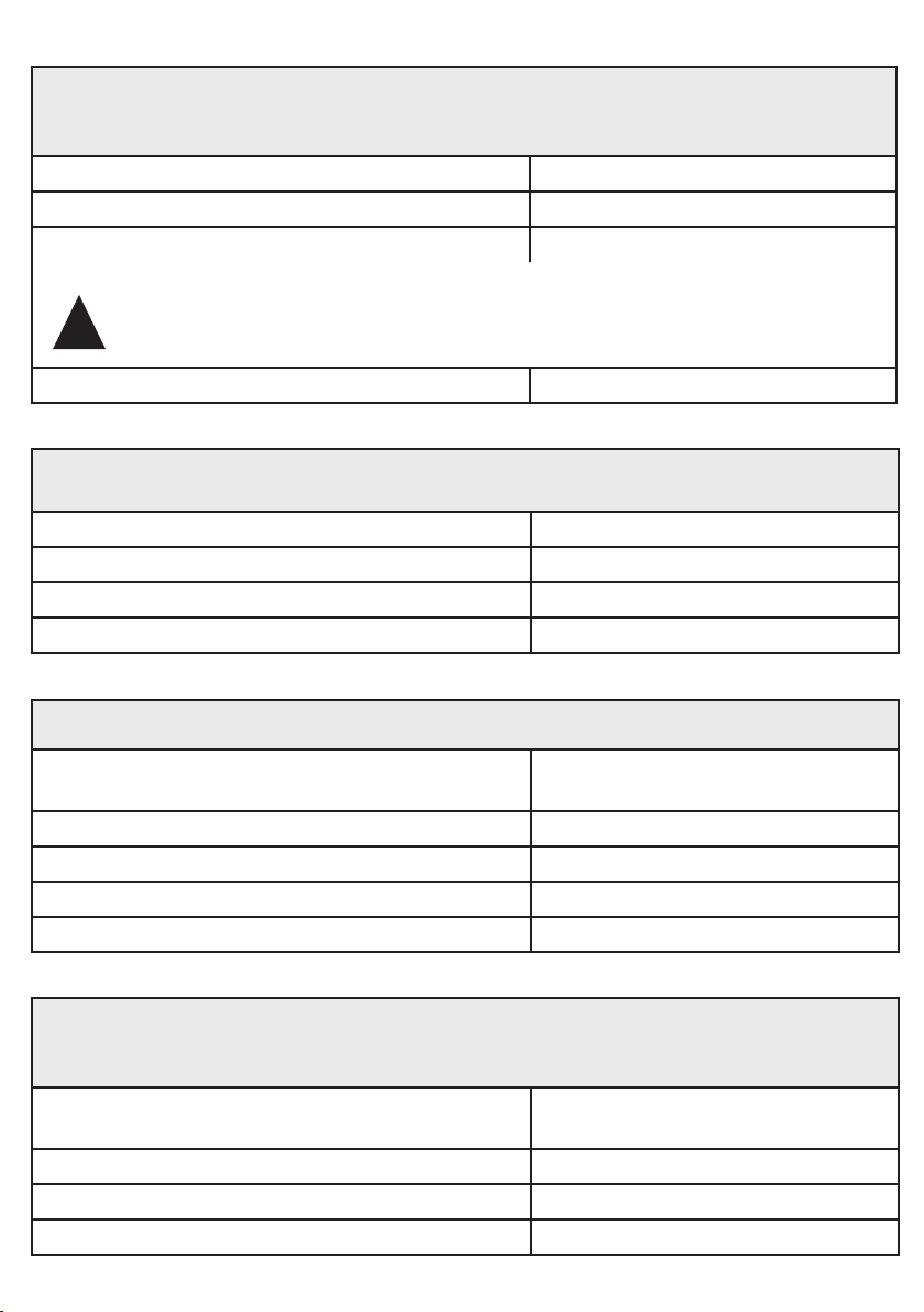
CARACTÉRISTIQUES TECHNIQUES
h x l x p
122,50 x 78,50
x 22,50 mm 0,7 kg 12/24V
AC/DC 110 mA
sortie
relais
= 2
30V DC - 2 A
125V AC - 0, 5 A
entrée
bouton poussoir
= 2
1010
Relais 1 = 1000
Relais 2 = 10
65*
KR1000-M
13,56 MHz
(MIFARE)
3 modes de fonctionnement :
●LECTEUR DE PROXIMITÉ
●LECTEUR DE PROXIMITÉ ou CODE
●LECTEUR DE PROXIMITÉ + CODE
ATTENTION :
dans ce cas, tous les utilisateurs doivent avoir 1 CODE et 1 BADGE DE PROXIMITE
0 - 99 s
-10+60°C
DIMENSIONS
*IP 65 : Protection contre les poussières, pas de dépôts nuisibles. Protection contre les jets d’eau à la lance de toutes directions
ATTENTION : Veuillez respecter la polarité et la tension d’alimentation 12/24V AC/DC !
Lire attentivement cette notice avant mise en service et utilisation.
Utiliser ce matériel pour une application adaptée. Le fabricant n’est pas responsable des dommages éventuels causés par
une utilisation contraire aux dispositions de sécurité.
Le montage, la maintenance et les réparations doivent être réalisés par un personnel spécialisé et autorisé.
La mise en oeuvre est très simple, mais une manipulation correcte et un entretien approprié sont des conditions essentielles
pour garantir un fonctionnement parfait.
1/24

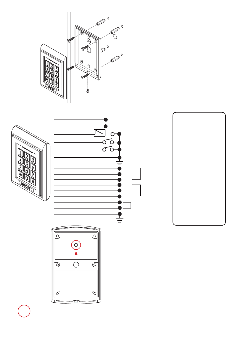
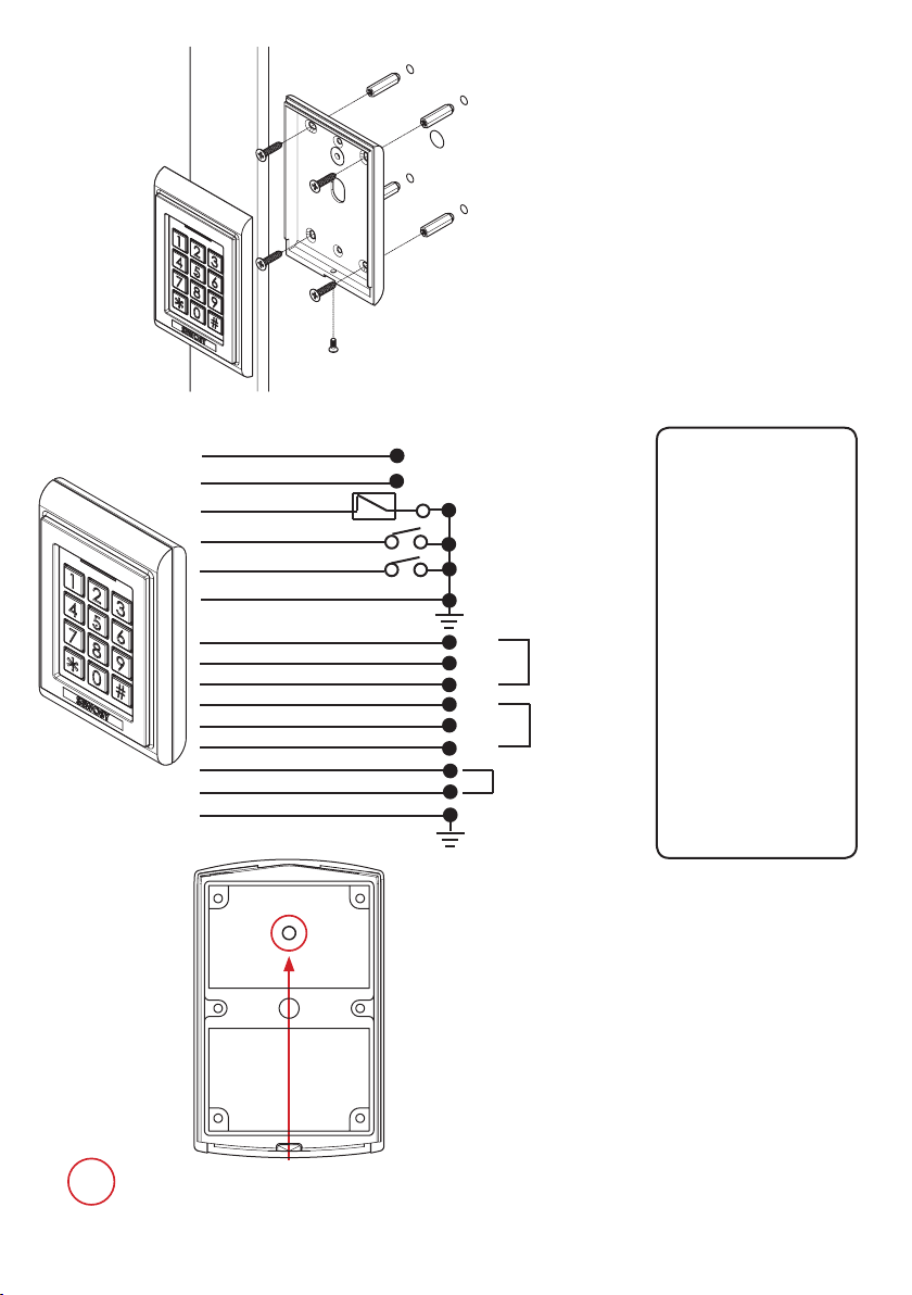
RACCORDEMENT
*CM (Contact magnétique) : Si branchement d’un contact magnétique de porte sur cette entrée, en cas de
temporisation assignée au contrôle d’accès, celle-ci s’annule lorsque que la porte est à nouveau fermée.
Cellule photoélectrique d’autoprotection. Pour l’activer se référer à la page 8/24 "Autoprotection"
BP 1
= Bouton poussoir
Relais 1
BP 2
= Bouton poussoir
Relais 2
CM
= Contact
Magnétique*
= Sonnette*
* Voir fonction
sonnette
en page 8/24
MONTAGE Ø6
Ø12
2/24
+
-
12-24V
AC/DC
Rouge
Noir
Brun
Jaune
Orange
Vert
BP1
BP2
CM
GND
NO 1
COM 1
NO 2
COM 2
NC 2
NC 1
Rose
Blanc
Violet
Gris
Vert clair
Bleu
Relais 1
Relais 2
Noir/Blanc
Brun/Blanc
Argent (écran)
Inutilisés
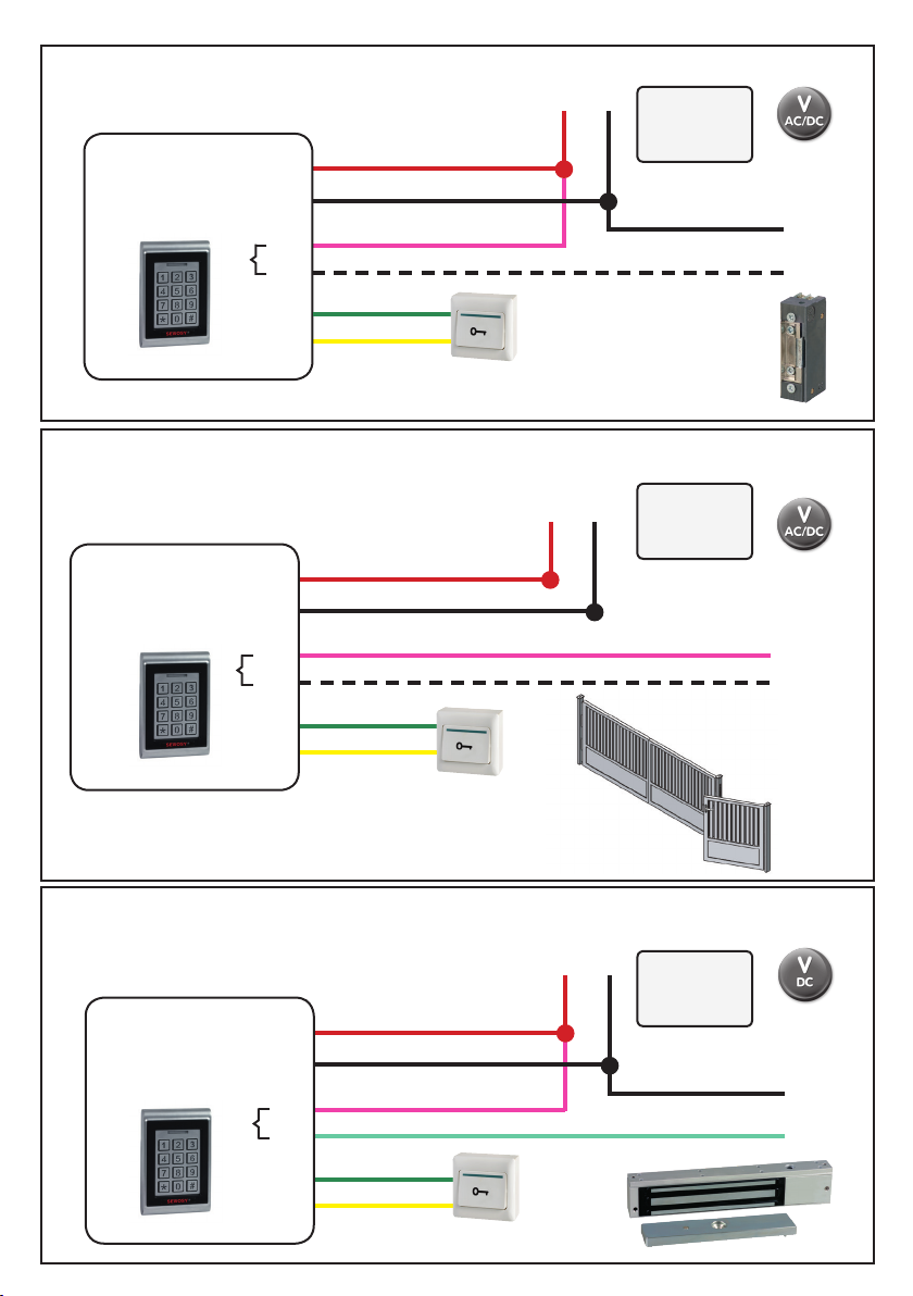
RACCORDEMENT D’UNE GÂCHE ELECTRIQUE*
VERROUILLAGE À ÉMISSION
12-24V
AC/DC
+
-
C
NO
AC ou DC
+
-
+-
en option
*exemple
12-24V
AC/DC
RACCORDEMENT D’UN PORTAIL*
VERROUILLAGE À ÉMISSION
12-24V
AC/DC
+
-
C
NO
NO
C
NO
+-
en option
*exemple
12-24V
AC/DC
RACCORDEMENT D’UNE VENTOUSE ÉLECTROMAGNÉTIQUE*
VERROUILLAGE À RUPTURE
12-24 V DC
+
-
C
NC
NO
DC
+
-
+-
en option
*exemple
12-24V
AC/DC
EXEMPLES DE CONFIGURATIONS
C
NO
C
NO
C
NO
GND
BP1
GND
BP1
GND
BP1
ALIMEN-
TATION
ALIMEN-
TATION
ALIMEN-
TATION
Rouge
Noir
Jaune
Vert
Rose
Blanc
Rouge
Noir
Jaune
Vert
Rose
Blanc
Rouge
Noir
Jaune
Vert
Rose
Vert Clair
NO
3/24
idéal pour portails

PROGRAMMATION
4/24
Modication du nombre de chires (codes)
Attention : à modier avant la première programmation d’un code
(réglage usine = 4 chires)
Entrer 2Xle code maître (code maître d’origine : 1234) BIP long + LED verte fixe
Entrer * 904 BIP long + LED verte clignotante
Entrer la valeur (Xcompris entre 2 et 6) BIP long + LED verte fixe
Entrer # # LED bleue fixe
Créer une carte maître
La carte maître vous permet de rentrer en programmation
Entrer 2Xle code maître (code maître d’origine : 1234) BIP long + LED verte fixe
Entrer * 7 LED verte clignotante
Passer la carte 1 X BIP long + LED verte fixe
Entrer # # LED bleue fixe
Modier une carte maître
Entrer 2Xle code maître ou passer la carte maître 1 X
(code maître d’origine : 1234) BIP long + LED verte fixe
Entrer * 7 LED verte fixe
Entrer ** BIP long + LED verte clignotante
Passer la carte 1 X BIP long + LED verte fixe
Entrer # # LED bleue fixe
Changer le code maître
Pour des raisons de sécurité il est recommandé de modier le code maître
permettrant de rentrer en programmation. Aucun code utilisateur ne peut être identique
Entrer 2Xle code maître ou passer la carte maître 1 X
(code maître d’origine : 1234) BIP long + LED verte fixe
Entrer * 3 LED verte clignotante
Entrer le nouveau code 2 X BIP long + LED verte fixe
Entrer # # LED bleue fixe
Une modication du nombre de chiffres efface tous les enregistrements
Si X= 2, le code maître est 12 Si X= 5, le code maître est 12345
Si X = 3, le code maître est 123 Si X= 6, le code maître est 123456
Si X= 4, le code maître est 1234
!
!Les codes ou cartes utilisateurs du relais 1 et 2 doivent être diérents
les uns des autres.
5/24
Ajouter un utilisateur
ATTENTION : Le code maître ne permet pas de déverrouiller la porte!
RELAIS 1 (de 001 à 999 utilisateurs)
CARTE OU CODE
Entrer 2Xle code maître ou passer la carte maître 1 X
(code maître d’origine : 1234) BIP long + LED verte fixe
Entrer * 001 BIP long + LED verte fixe
Entrer la position de 001 à 999
(3 digits obligatoires)LED verte fixe
si CARTE : Passer la carte 1 X
si CODE : Entrer un code 1 X BIP long + LED verte fixe
Entrer # # LED bleue fixe
RELAIS 2 (de 00 à 09 utilisateurs)
CARTE OU CODE
Entrer 2Xle code maître ou passer la carte maître 1 X
(code maître d’origine : 1234) BIP long + LED verte fixe
Entrer * 4 LED verte clignotante
Entrer la position de 00 à 09
(2 digits obligatoires)LED verte fixe
si CARTE : Passer la carte 1 X
si CODE : Entrer un code 1 X BIP long + LED verte clignotante
Entrer # # LED bleue fixe
CARTE ET CODE
(dans ce cas le relais 2 est inactif)
Entrer 2Xle code maître ou passer la carte maître 1 X
(code maître d’origine : 1234) BIP long + LED verte fixe
Entrer * 002 BIP long + LED verte fixe
Entrer la position de 001 à 999
(3 digits obligatoires)LED verte fixe
Passer la carte 1Xet entrer un code 1 X BIP long + LED verte fixe
Entrer # # LED bleue fixe

6/24
Supprimer un utilisateur
RELAIS 1 (de 001 à 999 utilisateurs)
Entrer 2Xle code maître ou passer la carte maître 1 X
(code maître d’origine : 1234) BIP long + LED verte fixe
Entrer la position à 3 digits obligatoires
(de 001 à999) LED rouge fixe
Entrer ** BIP long + LED verte fixe
Entrer # # LED bleue fixe
RELAIS 2 (de 00 à 09 utilisateurs)
Entrer 2Xle code maître ou passer la carte maître 1 X
(code maître d’origine : 1234) BIP long + LED verte fixe
Entrer * 4 LED verte clignotante
Entrer la position à 2 digits obligatoires
(de 00 à 09)LED rouge fixe
Entrer ** BIP long + LED verte fixe
Entrer # # LED bleue fixe
Supprimer tous les utilisateurs
Tous les codes et les cartes utilisateurs sont supprimés
Entrer 2Xle code maître ou passer la carte maître 1 X
(code maître d’origine : 1234) BIP long + LED verte fixe
Entrer * 888 BIP long + LED verte fixe
Entrer # # LED bleue fixe
Retour réglage d’usine
Cette manipulation eace tous les codes et cartes utilisateurs + la carte maître
et le code maître d’origine est restauré : 1234
Entrer 2Xle code maître ou passer la carte maître 1 X
(code maître d’origine : 1234) BIP long + LED verte fixe
Entrer * 899 BIP long + LED verte fixe
Entrer # # LED bleue fixe
7/24
Temporisation des relais
RELAIS 1 (de 01 à 99 secondes)
Entrer 2Xle code maître ou passer la carte maître 1 X
(code maître d’origine : 1234) BIP long + LED verte fixe
Entrer * 1 LED verte clignotante
Entrer la valeur à 2 digits obligatoires (de 01 à99 sec.)
ou entrer 00 (fonction bistable) BIP long + LED verte fixe
Entrer # # LED bleue fixe
RELAIS 2 (de 01 à 99 secondes)
Entrer 2Xle code maître ou passer la carte maître 1 X
(code maître d’origine : 1234) BIP long + LED verte fixe
Entrer * 5 LED verte clignotante
Entrer la valeur à 2 digits obligatoires (de 01 à99 sec.)
ou entrer 00 (fonction bistable) BIP long + LED verte fixe
Entrer # # LED bleue fixe
Restaurer le code maître d’origine (1234)
(en cas de code maître perdu ou oublié)
Couper l’alimentation du clavier.
Appuyer sur #. Maintenir cette touche appuyée 3 sec.
pendant que l’on rebranche l’alimentation
Les LED s’éteignent
BIP long + LED bleue fixe

8/24
Autoprotection
Active le buzzer en cas d’arrrachement
ACTIVER
Entrer 2Xle code maître ou passer la carte maître 1 X
(code maître d’origine : 1234) BIP long + LED verte fixe
Entrer * 6 LED verte clignotante
Entrer 02 BIP long + LED verte fixe
Entrer # # LED bleue fixe
DESACTIVER
Entrer 2Xle code maître ou passer la carte maître 1 X
(code maître d’origine : 1234) BIP long + LED verte fixe
Entrer * 6 LED verte clignotante
Entrer 01 BIP long + LED verte fixe
Entrer # # LED bleue fixe
Fonction sonnette
Si la fonction sonnette est activée,
les cartes et codes programmés ne sont plus fonctionnels sur le relais 2.
Cette fonction permet le remplacement d’une sonnette.
Pour sonner appuyer sur la touche *
ACTIVER
Entrer 2 X le code maître ou passer la carte maître 1 X
(code maître d’origine : 1234) BIP long + LED verte fixe
Entrer * 2 LED verte clignotante
Entrer 02 BIP long + LED verte fixe
Entrer # # LED bleue fixe
DESACTIVER
Entrer 2 X le code maître ou passer la carte maître 1 X
(code maître d’origine : 1234) BIP long + LED verte fixe
Entrer * 2 LED verte clignotante
Entrer 01 BIP long + LED verte fixe
Entrer # # LED bleue fixe
Remarque:Après 5 tentatives erronées consécutives (codes), le clavier sera bloqué durant 60
secondes. Aucune manipulation ne pourra être effectuée durant ces 60 secondes.

Technical changes reserved!
13b rue Saint-Exupéry - ZA de l’Aérodrome - CS20152 - FR-67503 HAGUENAU CEDEX www.sewosy.com
Tel. +33 (0)3 90 59 02 20 Fax + 33 (0)3 90 59 02 19
KR1000-M
ST_KR1000-M_A_170905
USER MANUAL
H x W x D
122,50 x 78,50
x 22,50 mm
0,65
kg
12/24V
AC/DC 110 mA
output
relays
= 2
30V DC - 2 A
125V AC - 0,5 A
input
exit button
= 2
1010
Relay 1 = 1000
Relay 2 = 10
65*
KR1000-M
13,56 MHz
(MIFARE)
3 operating modes :
●STAND-ALONE PROXIMITY READER
●STAND-ALONE PROXIMITY + PIN CODE
●STAND-ALONE PROXIMITY + PIN CODE
ATTENTION :
in this case, all users must have 1 PIN CODE and 1 PROXIMITY CARD
0 - 99 s
-10+60°C
DIMENSIONS
*IP 65 : Protection against intrusion of dust. Protection against low pressure water jets from any direction.
ATTENTION : Make sure to observe correct polarity and input voltage: 12/24V AC/DC as specied!
Read carefully this user guide before activating and using. Use this equipment only for an adapted application.
The manufacturer cannot be held responsible for possible damage caused when usual security requirements are not fulfilled.
Mounting, maintenance and repair must be carried out by a skilled and authorized staff.
The commissioning is easy, but a correct handling and an appropriate maintenance are mandatory to keep the device wor-
king perfectly.
TECHNICAL DATA
9/24
CONNECTION
*Door magnet = Detection of door status. When someone opens the door and comes in, the door is closed.
The system will automatically detect the door status and lock the door, even though there is still a delay period.
Anti-tamper photocell. To activate the function, please refer to page 16 «Anti-tamper function»
BP 1
= Exit Button
Relay 1
BP 2
= Exit Button
Relay 2
CM
= Door Magnet*
= Bell*
* Please refer to
Bell function
on page 16/24
MOUNTING Ø6
Ø12
10/24
+
-
12-24V
AC/DC
Red
Black
Brown
Yellow
Orange
Green
BP1
BP2
CM
GND
NO 1
COM 1
NO 2
COM 2
NC 2
NC 1
Pink
White
Purple
Grey
Light Green
Blue
Relay 1
Relay 2
Black/White
Brown/White
Silver (shield)
Unused

11/24
CONNECTION OF AN ELECTRIC STRIKE*
FAIL SECURE LOCKING
12-24V
AC/DC
+
-
C
NO
AC or DC
+
-
+-
optional
*example
12-24V
AC/DC
CONNECTION OF A GATE*
FAIL SECURE LOCKING
12-24V
AC/DC
+
-
C
NO
NO
C
NO
+-
optional
*example
12-24V
AC/DC
CONNECTION OF AN EM LOCK*
FAIL SAFE LOCKING
12-24 V DC
+
-
C
NC
NO
DC
+
-
+-
optional
*example
12-24V
AC/DC
EXAMPLES FOR TYPICAL WIRING CONFIGURATIONS
C
NO
C
NO
C
NO
GND
BP1
GND
BP1
GND
BP1
POWER
SUPPLY
POWER
SUPPLY
POWER
SUPPLY
Red
Black
Yellow
Green
Pink
White
Red
Black
Yellow
Green
Pink
White
Red
Black
Yellow
Green
Pink
Light Green
NO
ideal for gates
12/24
SETTING MODE
Changing number of digits (codes)
Attention: this modication must be done before the rst programming of a code
(factory setting = 4 digits)
Enter the master code 2 X (Default code is 1234) long BEEP + LED will turn green
Enter * 904 long BEEP + LED will flash green
Enter the digits (Xis from 2 to 6) long BEEP + LED will turn green
Enter # # LED will turn blue
Create a master card
The master card allows to open the setup session
Enter the master code 2 X (Default code is 1234) long BEEP + LED will turn green
Enter * 7 LED will flash green
Swipe the card 1 X long BEEP + LED will flash green
Enter # # LED will turn blue
Changing a master card
Enter the master code 2Xor swipe the master card 1 X
(Default code is 1234) long BEEP + LED will turn green
Enter * 7 LED will turn green
Enter ** long BEEP + LED will flash green
Swipe the card 1 X long BEEP + LED will turn green
Enter # # LED will turn blue
Changing a master code
It is recommended to modify the master code which allows to open the setup
session for security reasons.The user codes must be dierent from mastercode
Enter the master code 2Xor swipe the master card 1 X
(Default code is 1234) long BEEP + LED will turn green
Enter * 3 LED will flash green
Enter the new code 2 X long BEEP + LED will turn green
Enter # # LED will turn blue
!
Changing digit number erases all previous records!
If X= 2 the master code is 12 If X= 5 the master code is 12345
If X = 3 the master code is 123 If X= 6 the master code is 123456
If X= 4 the master code is 1234

13/24
!The codes or user cards from relay 1 and 2 must be dierent from each
other.
Add a user
ATTENTION: Please note that the master code don’t unlock the door!
RELAY 1 (from 001 to 999 users)
CARD OR CODE
Enter the master code 2Xor swipe the master card 1 X
(Default code is 1234) long BEEP + LED will turn green
Enter * 001 long BEEP + LED will turn green
Enter the position from 001 to 999
(3 mandatory digits)LED will turn green
if CARD : Swipe the card 1 X
if CODE : Enter a code 1 X long BEEP + LED will turn green
Enter # # LED will turn blue
RELAY 2 (from 00 to 09 users)
CARD OR CODE
Enter the master code 2Xor swipe the master card 1 X
(Default code is 1234) long BEEP + LED will turn green
Enter * 4 LED will flash green
Enter the position from 00 to 09
(2 mandatory digits)LED will turn green
if CARD : Swipe the card 1 X
if CODE : Enter a code 1 X long BEEP + LED will flash green
Enter # # LED will turn blue
CARD AND CODE
in this case the relay 2 is in idle state (inactive)
Enter the master code 2Xor swipe the master card 1 X
(Default code is 1234) long BEEP + LED will turn green
Enter * 002 long BEEP + LED will turn green
Enter the position from 001 to 999
(3 mandatory digits)LED will turn green
Swipe the card 1Xand enter a code 1 X long BEEP + LED will turn green
Enter # # LED will turn blue

14/24
Delete one user
RELAY 1 (from 001 to 999 users)
Enter the master code 2Xor swipe the master card 1 X
(Default code is 1234) long BEEP + LED will turn green
Enter the position (3 mandatory digits)
(from 001 to 999) LED will turn red
Enter ** long BEEP + LED will turn green
Enter # # LED will turn blue
RELAY 2 (from 00 to 09 users)
Enter the master code 2Xor swipe the master card 1 X
(Default code is 1234) long BEEP + LED will turn green
Enter * 4 LED will flash green
Enter the position (2 mandatory digits)
(from 00 to 09) LED will turn red
Enter ** long BEEP + LED will turn green
Enter # # LED will turn blue
Delete all users
All user codes and cards will be removed
Enter the master code 2Xor swipe the master card 1 X
(Default code is 1234) long BEEP + LED will turn green
Enter * 888 long BEEP + LED will turn green
Enter # # LED will turn blue
Return to factory settings
This operation removes all user codes + cards + master card
and restores factory settings: default code will be 1234 again
Enter the master code 2Xor swipe the master card 1 X
(Default code is 1234) long BEEP + LED will turn green
Enter * 899 long BEEP + LED will turn green
Enter # # LED will turn blue

15/24
SETTING OF THE UNLOCKING TIME
RELAY 1 (from 01 to 99 seconds)
Enter the master code 2Xor swipe the master card 1 X
(Default code is 1234) long BEEP + LED will turn green
Enter * 1 LED will flash green
Enter the 2-digits value (mandatory): from 01 to 99 sec.
or enter 00 (for bistable function) long BEEP + LED will turn green
Enter # # LED will turn blue
RELAY 2 (from 01 to 99 seconds)
Enter the master code 2Xor swipe the master card 1 X
(Default code is 1234) long BEEP + LED will turn green
Enter * 5 LED will flash green
Enter the 2-digits value (mandatory): from 01 to 99 sec.
or enter 00 (for bistable function) long BEEP + LED will turn green
Enter # # LED will turn blue
How to restore the default master code (1234)
(in case of lost or forgotten master code)
Switch off the power supply from the keypad
Press #key. Keep it pressed for 3 seconds while
powering the device again
all LEDs light off
long BEEP + LED will turn blue

16/24
Tamper function
This function activates the buzzer in case of tear-o attempt
to ENABLE the tamper function
Enter the master code 2Xor swipe the master card 1 X
(Default code is 1234) long BEEP + LED will turn green
Enter * 6 LED will flash green
Enter 02 long BEEP + LED will turn green
Enter # # LED will turn blue
to DISABLE the tamper function
Enter the master code 2Xor swipe the master card 1 X
(Default code is 1234) long BEEP + LED will turn green
Enter * 6 LED will flash green
Enter 01 long BEEP + LED will turn green
Enter # # LED will turn blue
Bell function
If the bell function is activated,
the programmed cards and codes will no longer be functional on relay 2.
This function could be used as a bell.
Press on * key to ring the bell.
to ENABLE the bell function
Enter the master code 2Xor swipe the master card 1 X
(Default code is 1234) long BEEP + LED will turn green
Enter * 2 LED will flash green
Enter 02 long BEEP + LED will turn green
Enter # # LED will turn blue
to DISABLE the bell function
Enter the master code 2Xor swipe the master card 1 X
(Default code is 1234) long BEEP + LED will turn green
Enter * 2 LED will flash green
Enter 01 long BEEP + LED will turn green
Enter # # LED will turn blue
Remark:If three consecutive keyboard input errors occured, the keyboard will be locked for 60
seconds. Any keyboard operation is invalid within 60 seconds.

Änderungen vorbehalten!
13b rue Saint-Exupéry - ZA de l’Aérodrome - CS20152 - FR-67503 HAGUENAU CEDEX www.sewosy.com
Tel. +33 (0)3 90 59 02 20 Fax + 33 (0)3 90 59 02 19
KR1000-M
ST_KR1000-M_A_170905
BEDIENUNGSANLEITUNG
TECHNISCHE DATEN
H x B x T
122,50 x 78,50
x 22,50 mm 0,65 kg 12/24V
AC/DC 110 mA
Relais
Ausgang
= 2
30V DC - 2 A
125V AC - 0,5 A
Druckknopf
Eingang
= 2
1010
Relais 1 = 1000
Relais 2 = 10
65*
KR1000-M
13,56 MHz
(MIFARE)
3 Betriebsmodus:
●BERÜHRUNGSLOSER KARTENLESER
● KARTENLESER oder TÜRCODESYSTEM
●BERÜHRUNGSLOSER KARTENLESER + CODE
ACHTUNG:
in diesem Fall müssen alle Benutzer 1 CODE und 1 BERÜHRUNGSLOSE KARTE besitzen
ABMESSUNGEN
*IP 65 : staubdicht. Schutz gegen Strahlwasser.
ACHTUNG: Anschlußpolarität und Höhe der Betriebsspannung beachten (12/24V AC/DC)!
Vor der Inbetriebnahme, bitte diese Anleitung sorgfältig lesen. Dieses Material nur für vorgesehene Anwendungen einsetzen.
Der Hersteller leistet keine Gewähr für Schäden die durch fehlerhafte Montage oder nicht einhalten von Sicherheits-
vorschriften entstehen.
Die Montage, die Wartung und Reparaturen dürfen nur durch sachkundiges Personal durchgeführt werden.
Die Montage ist sehr einfach, aber eine korrekte Verarbeitung und ein entsprechender Unterhalt sind grundsätzliche Bedin-
gungen für eine einwandfreie Funktion.
0 - 99 s
-10+60°C
17/24
ANSCHLUß
Fotozelle für Sabotagealarm. Um diese Funktion zu aktivieren, Siehe Seite 24/24 «Sabotagealarm»
BP 1
= Druckknopf
Relais 1
BP 2
= Druckknopf
Relais 2
CM
= Magnetkontakt*
MONTAGE
= Klingel*
* Siehe
Klingeltaster
Funktion
Seite 24/24
*Magnetkontakt = Türzustandsanzeige. Falls jemand die Tür geöffnet hat und eingetreten ist, und diese danach
wieder geschlossen ist, detektiert das Gerät automatisch die Türposition und verriegelt die Tür. Dies erfolgt
obgleich eine Entriegelungszeit eingestellt wurde.
Ø6
Ø12
18/24
+
-
12-24V
AC/DC
Rot
Schwarz
Braun
Gelb
Orange
Grün
BP1
BP2
CM
GND
NO 1
COM 1
NO 2
COM 2
NC 2
NC 1
Rosa
Weiß
Violett
Grau
Hell Grün
Blau
Relais 1
Relais 2
Schwarz/Weiß
Braun/Weiß
Silber (schirm)
Unnötig

19/24
ARBEITSSTROM VERRIEGELUNG
MIT TÜRÖFFNER ANSCHLUß*
12-24V
AC/DC
+
-
C
NO
AC oder DC
+
-
+-
optional
*Beispiel
12-24V
AC/DC
ARBEITSSTROM VERRIEGELUNG
MIT AUSSENTOR ANSCHLUß*
12-24V
AC/DC
+
-
C
NO
NO
C
NO
+-
optional
*Beispiel
12-24V
AC/DC
RUHESTROM VERRIEGELUNG
MIT HAFTMAGNET ANSCHLUß*
12-24 V DC
+
-
C
NC
NO
DC
+
-
+-
optional
*Beispiel
12-24V
AC/DC
BEISPIELANSCHLUßKONFIGURATIONEN
C
NO
C
NO
C
NO
GND
BP1
GND
BP1
GND
BP1
NETZTEIL
Rot
Schwarz
Gelb
Grün
Violett
Weiß
Rot
Schwarz
Gelb
Grün
Violett
Weiß
Rot
Schwarz
Gelb
Grün
Violett
Hell Grün
NO
für Tore geeignet
NETZTEIL
NETZTEIL

20/24
Änderung der Ziernanzahl (Codes)
Achtung: diese Änderung muss vor der ersten Codeprogrammierung erfolgen
(Werkeinstellung = 4 Ziern)
2XMastercode eingeben (Ursprungsmastercode: 1234) langer PIEP Ton + gelbe LED leuchtet
* 904 eingeben langer PIEP Ton + grüne LED blinkt
Neuer Wert eingeben (Xzwischen 2 und 6 begriffen) langer PIEP Ton + grüne LED leuchtet
# # eingeben blaue LED leuchtet
Masterkarte kreieren
Die Masterkarte ermöglicht in den Programmiermodus zu gelangen
2XMastercode eingeben (Ursprungsmastercode: 1234) langer PIEP Ton + gelbe LED leuchtet
* 7 eingeben grüne LED blinkt
1XKarte an den Leser halten langer PIEP Ton + grüne LED leuchtet
# # eingeben blaue LED leuchtet
Masterkarte ändern
2XMastercode eingeben oder 1XMasterkarte an den
Leser halten (Ursprungsmastercode: 1234) langer PIEP Ton + grüne LED leuchtet
* 7 eingeben grüne LED leuchtet
** eingeben langer PIEP Ton + grüne LED blinkt
1XKarte an den Leser halten langer PIEP Ton + grüne LED leuchtet
# # eingeben blaue LED leuchtet
Mastercode ändern
Der Mastercode ermöglicht in den Programmiermodus zu gelangen. Sicherheitshal-
ber wird empfohlen ihn zu ändern. Es darf kein Benutzercode identisch sein.
2XMastercode eingeben oder 1XMasterkarte an den
Leser halten (Ursprungsmastercode: 1234) langer PIEP Ton + gelbe LED leuchtet
* 3 eingeben grüne LED blinkt
Neuer Code 2Xeingeben langer PIEP Ton + grüne LED leuchtet
# # eingeben blaue LED leuchtet
PROGRAMMIERUNG
Eine Änderung der Ziffernanzahl löscht alle vorrige Speicherungen!
Falls X= 2, ist der Mastercode 12 Falls X= 5, ist der Mastercode 12345
Falls X = 3, ist der Mastercode 123 Falls X= 6, ist der Mastercode 123456
Falls X= 4, ist der Mastercode 1234
!
Other manuals for KR1000-M
1
Table of contents
Languages:
Other Sewosy Keypad manuals


