Protege EliteSuite Eclipse User manual

ELT-KLES
Protégé® EliteSuite® Eclipse LED Keypad
Installaon Manual

The specicaons and descripons of products and services contained in this manual were correct at the me of prinng. Integrated Control Technology Limited
reserves the right to change specicaons or withdraw products without noce. No part of this document may be reproduced, photocopied, or transmied in any
form or by any means (electronic or mechanical), for any purpose, without the express wrien permission of Integrated Control Technology Limited. Designed and
manufactured by Integrated Control Technology Limited. EliteSuite® and the EliteSuite® Logo are registered trademarks of Integrated Control Technology Limited. All
other brand or product names are trademarks or registered trademarks of their respecve holders.
Copyright © Integrated Control Technology Limited 2003-2010. All rights reserved.

Table of Contents
1.0 Welcome ............................................................................................................................2
2.0 Protégé®System Products ..................................................................................................3
2.1 Protégé® System Management Suite .................................................................................. 3
2.2 Protégé® EliteSuite® Modules ............................................................................................. 3
3.0 Mounng ...........................................................................................................................4
4.0 Wiring and Conguraon....................................................................................................5
4.1 Wire Loom........................................................................................................................... 5
4.2CommunicaonConnecon ................................................................................................ 6
4.3 Zone Input Wiring................................................................................................................ 7
4.4 Fire Zone Input Wiring......................................................................................................... 9
5.0 Programmable Ouput .......................................................................................................10
6.0 Indicator Lights.................................................................................................................11
6.1 Arm/Armed Indicator ........................................................................................................ 11
6.2 Ready Indicator ................................................................................................................. 12
6.3 Power/Trouble Indicator ................................................................................................... 12
6.4 Message Indicator............................................................................................................. 12
6.5 Zone Display...................................................................................................................... 12
7.0 Audible Tones...................................................................................................................13
7.1ConguraonTone............................................................................................................ 13
7.2 Entry Request Tone............................................................................................................ 13
7.3RejeconTone ................................................................................................................... 13
8.0 Keypad Operaon.............................................................................................................14
8.1SecondFuncon ................................................................................................................ 15
9.0 Device Conguraon ........................................................................................................16
9.1 EnteringDeviceConguraonMode ................................................................................ 16
9.2AddressSelecon(Menu1)............................................................................................... 17
9.3DeviceOpons(Menu2)................................................................................................... 17
9.4BacklightLevel(Menu3)................................................................................................... 18
9.5FirmwareVersion(Menu4)............................................................................................... 19
9.6DeviceDefault(Menu5).................................................................................................... 19
9.7ExingDeviceConguraonMode................................................................................... 19
10.0 Local Installer Login ..........................................................................................................20
11.0 Timing ..............................................................................................................................21
11.1 EntryDelayTimer(Menu1,1) ........................................................................................ 21
11.2ExitDelayTimer(Menu1,2)........................................................................................... 21
11.3Alarm/SirenTimer(Menu1,3) ....................................................................................... 22

12.0 Opons (Menu 2) .............................................................................................................23
12.1GeneralOpons(Menu2,1)........................................................................................... 23
12.2ArmingOpons(Menu2,2)............................................................................................ 25
12.3ReporngOpons(Menu2,3)........................................................................................ 26
12.4PanicOpons(Menu2,4)............................................................................................... 28
13.0 Zones................................................................................................................................29
13.1SelecngaZone .............................................................................................................. 29
13.2 Zone Type ........................................................................................................................ 29
13.3ZoneOpons ................................................................................................................... 30
14.0 Conguraon via Protégé® ...............................................................................................31
14.1ConnecngtotheModule............................................................................................... 31
14.2 General Setup Tab ........................................................................................................... 32
14.3 Users Setup Tab............................................................................................................... 33
14.4 System Setup Tab ............................................................................................................ 35
14.5OponsSetupTab ........................................................................................................... 37
15.0 Quick Reference ...............................................................................................................41
15.1ConguraonMenu ........................................................................................................ 41
15.2 Installer Menu ................................................................................................................. 42
15.3 User Menu....................................................................................................................... 44
16.0 Mechanical Diagram .........................................................................................................45
17.0 Technical Diagram.............................................................................................................46
18.0 Technical Specicaons ....................................................................................................47
19.0 Ordering Informaon........................................................................................................48
20.0 Warranty ..........................................................................................................................49
!Indicates a warning or advisory message relang to the secon or locaon.
?Indicates a hint or suggeson that relates to the secon or locaon.
[TEXT] Bold text enclosed in brackets is used to show a secon number or address of
a programmable opon or informaon on programming shortcut sequences.
Italics Italic text shows a reference to a example, secon, page, manual or website.
1.0 Welcome!
Thank you for purchasing the Protégé® EliteSuite® Eclipse LED Keypad (ELT-KLES) by Integrated
Control Technology Limited. The EliteSuite® System is an advanced technology security system
specically designed to enhance the funconality of condominium and apartment security with
exible local monitoring and osite communicaon.
The Protégé® EliteSuite® Eclipse LED Keypad is a complete modern security system for alarming
your facitlity. A sleek, stylish alternave, this keypad ts in with modern décor while sll providing
a user friendly interface to the Protégé® EliteSuite® alarm funcons. Operang in the
Condominium Control mode the Protégé® EliteSuite® Eclipse LED Keypad provides a complete
standalone 8 zone, 8 user local alarm system.
The current features of the Protégé® EliteSuite® Eclipse LED Keypad include:
• 4x onboard zones (8 with duplex zone operaon)
• 1x PGM Output
• Congurable security opons
• Capacive touch keypad
• Can funcon as part of the Protégé® EliteSuite® or as a complete standalone soluon
• Fire, Panic, and Medical Alarm opons
• 8x separate User codes
When receiving the Protégé® EliteSuite® Eclipse LED Keypad you should nd the kit contains the
items listed below. The kit type is clearly labelled on the packaging and will tell you what your kit
contains. Please note that if you do not have the correct contents contact your distributor
immediately.
• Protégé® EliteSuite® Eclipse LED Keypad
• Protégé® EliteSuite® Eclipse LED Keypad User Manual
• 10 way wiring loom
• 8x 1k resistors
• 4x 2k4 resistors
2

3
2.0 Protégé® System Products
2.1 Protégé® System Management Suite
The Protégé® System Management Suite applicaon is a Windows®™ Vista (Business/Ulmate),
XP Professional and Server 2003 Integrated Access Control and Alarm Management System
designed for any conguraon from single site, single Protégé® Integrated System Controller
applicaons up to the global mul-naonal corporaons using mulple site, mulple Protégé®
Integrated System Controller installaons.
Product Code Descripon
PRT-SMGT-ENT Protégé® System Management Suite Enterprise Edion
PRT-SMGT-PRO Protégé® System Management Suite Professional Edion
PRT-SMGT-STN Protégé® System Management Suite Standard Edion
PRT-SMGT-1U Protégé® System Management Suite Single Client License Edion
Product Code Descripon
ELT-TLCD Protégé® EliteSuite® Touchscreen Keypayd
ELT-KLCD Protégé® EliteSuite® Alphanumeric LCD Keypad
ELT-KLED Protégé® EliteSuite® Icon LED Keypad
2.2 Protégé® EliteSuite® Modules
The Protégé® System can be expanded to accommodate large numbers of modules using the
encrypted RS-485 Network. Modules that are currently available are listed below. Visit
www.integratedcontroltechnology.comforthelatestProtégé®Moduleandproductinformaon.

3.0 Mounng
The Protégé® EliteSuite® Eclipse LED Keypad maintains complete control of your residence.
All the acons performed in your security system will be executed through the Protégé® EliteSuite®
Eclipse LED Keypad. It is intended to be mounted on a wall.
Step 1
Select where to mount the Protégé® EliteSuite® Eclipse LED Keypad.
Step 2
Remove the rear half of the Protégé® EliteSuite® Eclipse LED Keypad by depressing the retaining
clip and rotang the case halves apart.
Step 3
Hold the rear case half against the wall and mark the mounng holes and cable entry area.
The cable entry area should align with a hole cut through the plaster wall-board. Cables are
intended to be run inside the wall. Use appropriate screws (not supplied) to ax the case to the
wall.
Step 4
Run the wiring. Refer to later secons of this manual for the electrical connecons. Leave about
20cm (8”) of wire protruding through the center of the mounted half of the case.
Step 5
Connect the wiring to the Protégé® EliteSuite® Eclipse LED Keypad electronics, then, to clip the
case together, hook the top edges together then rotate and press the boom in unl you hear the
clip snap into place.
4

4.0 Wiring and Conguraon
The wiring structure of the Protégé® EliteSuite® Eclipse LED Keypad uses an encrypted RS-485
communicaon interface. Connecons should be made in a daisy chain conguraon, avoiding star
and stub connecons.
4.1 Wire Loom
The Protégé® EliteSuite® Eclipse LED Keypads are supplied with a wire loom aachment and are
connected using a keyed 10 posion snap lock connector. The 10 way wiring loom connecon uses
the following color coding.
Figure 2 - Wiring Loom Color Coding and Funcon
YELLOW
GRAY
PURPLE
ORANGE
BLACK
WHITE
BLUE
BROWN
GREEN
RED
(0V)
(+12V)
System controller
network communicaon
terminals and module
network.
NA
NB
ZONE 1 (1+2)
ZONE 2 (3+4)
PGM 1
(OUTPUT)
ZONE 3 (5+6)
ZONE 4 (7+8)
0V
Zone inputs and
PGM Output.
Figure 1 - Condominium Eclipse LED Keypad Communicaon
ELT-KLES - Protégé® EliteSuite® Eclipse LED Keypads
Encrypted RS-485 Module Network Encrypted RS-485 Module Network
5
!
When using more than one power supply to supply mulple wiring runs of
Protégé® EliteSuite® Eclipse LED Keypad connect the +12V terminals of only
ONE power supply unit to the N+ and N- terminals of the controller. Each power
supply unit should have the common (0V or -) connected together to ensure a
common 0V.
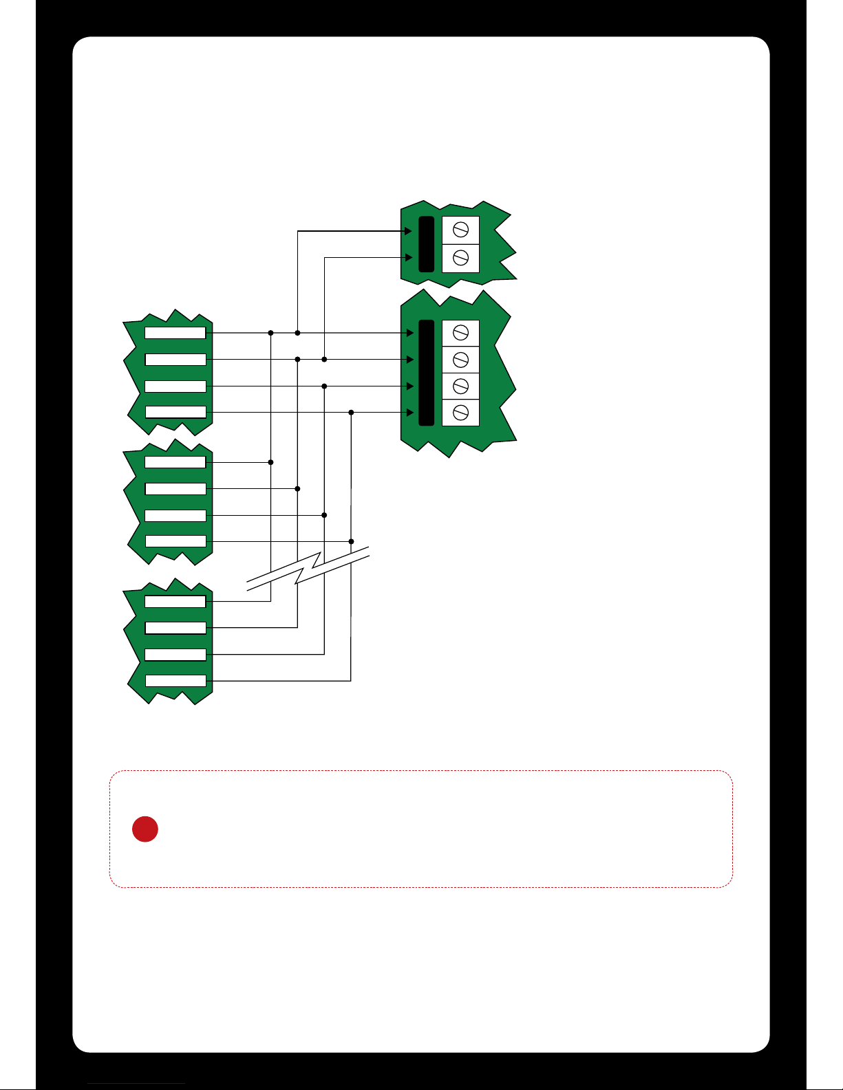
4.2CommunicaonConnecon
Support for up to 250 keypads per condominium controller is provided. Connecon to the system
controller uses the network communicaon RS-485 interface. The Protégé® EliteSuite® Eclipse LED
Keypad also requires power to be supplied to the N+ and N- terminals.
KEYPAD #1
KEYPAD #2
KEYPAD #250
+12V
0V
NA
NB
+12V
0V
NA
NB
+12V
0V
NA
NB
N+ N- NA NB
+
-
External +12V power supply. If more than one
power supply is used ensure that the 0V (-) is
connected to all other power supply devices powering
modules on the same system controller.
System Controller network communica�on
terminals and module network.
RED
BLACK
BLUE
WHITE
RED
BLACK
BLUE
WHITE
RED
BLACK
BLUE
WHITE
Figure 3 - Communicaon Connecon
6
4.3 Zone Input Wiring
The Protégé® EliteSuite® Eclipse LED Keypad is capable of connecng to 8 zone inputs, each zone
input can then be programmed to perform the required funcon in the system.
The following diagrams show each of the zone wiring conguraon sengs that are possible.
The programmed zone conguraon for the Protégé® EliteSuite® Eclipse LED Keypad is made in the
opon sengs. RefertotheGeneralOponssecononpage23forprogrammingofthezone
conguraon.
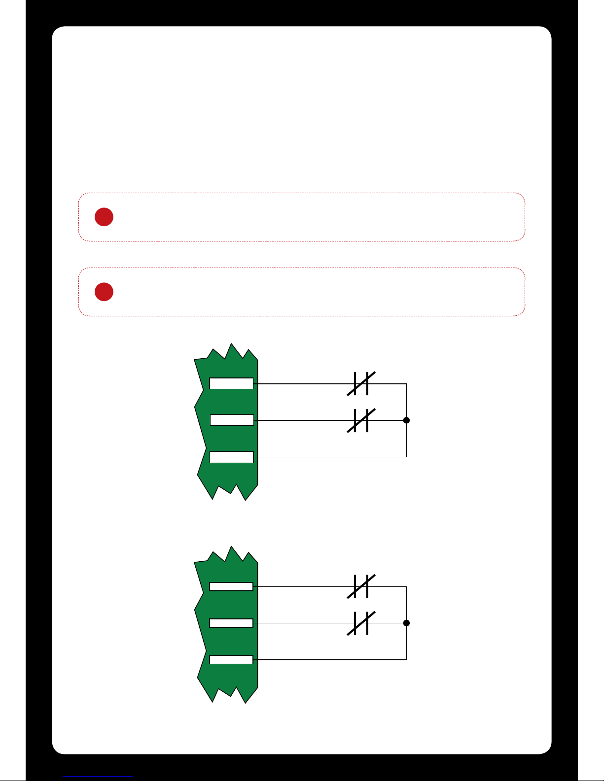
!When using a tamper input on a device the tamper contacts must be normally
closed and wired in series.
!All resistors required to wire the zone conguraons are provided with the
Protégé® EliteSuite® Eclipse LED Keypad in the accessory bag.
Figure 5 - Zone Input (No Resistors)
Figure 4 - Zone Input (No Resistors)
Zone 1 (1+2)
Zone 1
N.C. Zone Contact
0V
Zone 2
N.C. Zone Contact
Zone 2 (3+4)
PURPLE
ORANGE
BLACK
Zone 3
Zone 3
N.C. Zone Contact
0V
Zone 4
N.C. Zone Contact
Zone 4
YELLOW
GREEN
GREY
7
Table of contents


