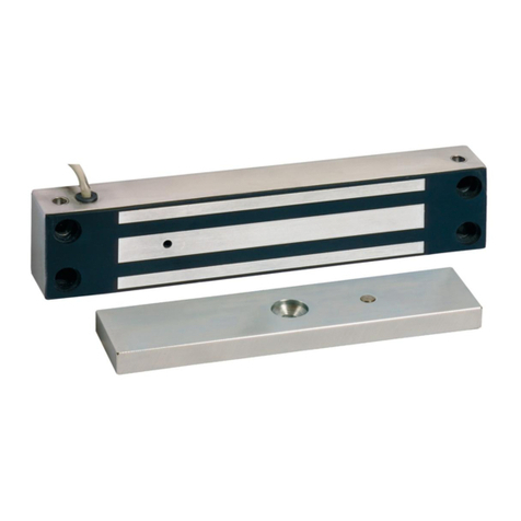
Sewosy CPREG-4 Series User manual

Sous réserve de modifications techniques - Technical changes reserved! - Änderungen vorbehalten!
13b rue Saint-Exupéry ▪ZA de l'Aérodrome ▪CS 20152 ▪F- 67503 HAGUENAU CEDEX www.sewosy.eu 33 (0)3 90 59 02 20 33 (0)3 90 59 02 19
ST_CPREG-4_RANGE_A_150218 1/24
NOTICE DE MISE EN OEUVRE
IMPLEMENTATION MANUAL
BETRIEBSANLEITUNG
BANDEAUX MODULAIRES CPREG-4
CPREG-4 MODULAR ALUMINIUM HOUSINGS
CPREG-4 ALUMINIUM MODULARPROFILE
ISO4026
M4x5 ST 3.5x25
ISO7380
M6x20
DIN6797
A4,6
Insert
M6
Kit de sertissage
Crimping kit
Montagewerkzeug
CPREG-4/S4
CPREG-4
S4
S2
S1
S4
S2
S1
S4
S2
S1
CPREG-4/S1CPREG-4/S2
S4
Composition des kits / Bill of Material / Verpackungsinhalt
Carte électronique
Electronic board
Steuerplatine
Manchon d'assemblage pré-percé pour le prol carré
Predrilled assembling muff for the square prole
Vorgebohrte Verbindungsmuffe für das viereckige Prol
Elément de jonction pour la poignée
Junction unit for the armature plate prole
Zwischensstück für den Griff
1x
4 x
8 x 13 x 13 x
2 x 4 x 7 x 7 x
3 x
2 x 1 x 1x
2 x
4 x 4 x 4 x
1 x
/
1 x
1 x
1 x
PV N°
Embout de
nition du prol
carré
End cap for the
armature plate
prole
Endstück für
das viereckige
Prol
Câble plat
Flat cable
Flachkabel
GABARITS DE PERCAGE
DRILLING TEMPLATES
BOHRSCHABLONEN
S4
S2
S1
ATTENTION : Lire attentivement cette notice AVANT l'installation et la mise en service.
ATTENTION : BEFORE commissioning and operating, please read this manual carefully.
ACHTUNG : Lesen Sie bitte diese Betriebsanleitung aufmerksam durch, bevor Sie die Anlage installieren und in Betrieb setzen.
1 x DIN
DROITE
1 x DIN
GAUCHE
1 x S2-S1
2 x S4
CALE DE POSITIONNEMENT
POSITIONING WEDGE
AUSRICHTUNGSHILFE
ATTENTION : certication NF S 61-937 uniquement pour les tensions 24V DC et 48V DC
SD 15 00 55

2/24
Il est primordial de respecter étape par étape le montage décrit ci-après, qui garantit le bon fonctionnement et
l'efcacité du bandeau.
It is essential to follow step by step the process described hereafter, which will ensure the aluminium housing
will work properly and efciently.
Damit die optimale Haltekraft erreicht wird, muss das Prol gewissenhaft montiert und ausgerichtet sein.
Beachten Sie bitte bei der Montage die vorgegebene Reihenfolge.
Table des matières - Contents - Inhalt (page n° - page Nr. - Seite Nr.)
Outillage requis
Required tools
Benötigtes Werkzeug
Ø 9,5
2,5 x 35
Indispensable pour éviter la casse du
bornier lors du raccordement.
Essential to prevent damage of the screw
terminal during connection operation.
Notwendig um die Schraubklemmen
während der Anschlussarbeiten nicht zu
beschädigen.
En option - Optional
PZ1
PH2
Caractéristiques techniques
Technical specications
Technische Daten
Dimensions
Dimensions
Abmessungen
Gabarit (choix - positionnement)
Template (choice - positioning)
Schablone (Wahl - positionieren)
Raccordement des câbles plats
Connection of the at wires
Anschluß der Flachkabel
Raccordement de la platine
Connection of the electronic board
Anschluß der Steuerplatine
Raccordement du bandeau
Connection of the prole
Anschluß des Prols
3 13
4 15
9
5-8 16
Montage du prol carré
Mounting of the square prole
Montage des viereckigen Prols
Montage de la poignée
Mounting of the hand grip
Montage des Griffes
10-17
18-23
Utilisation du kit de sertissage
Using the crimping kit
Verwendung des Crimpwerkzeugs

3/24
CPREG-4
VALEURS POUR UNE VENTOUSE*
VALUES FOR ONE MAGNET*
WERTE FÜR EINEN HAFTMAGNETEN*
Plage de tension d’alimentation / Supply voltage range / Spannungsbereich 12V DC →48V DC (-10% / +15%)
Puissance absorbée / Power requirement / Leistungsaufnahme 3,5 W*
Consommation en courant / Current consumption / Stromaufname
12VDC 250 mA*
24VDC 130 mA*
48VDC 73 mA*
Température d’utilisation / Operating temperature / Temperaturbereich -10°C +60°C
Indice de protection / Protection index / Schutzklasse IP42
Force de retenue nominale / Nominal holding force / Haltekraft 300 daN (▲)
Dimensions / Dimensions / Abmessungen
1330 mm x 105 mm x 67,5 mm
756 mm x 105 mm x 67,5 mm
469 mm x 105 mm x 67,5 mm
Pouvoir de coupure du contact de signalisation
Status sensor switching capability
Schaltbelastbarkeit des Rückmeldekontakts
125V AC/2A 30V DC/2A
(▲) Forces de retenue maximales théoriques, pour une mise en oeuvre respectant les conditions de pose optimales.
Maximal theoretical holding force for implementation fulllling optimal installation conditions
Maximale theoretische Haftkräfte unter optimalen Montagebedingungen.
Caractéristiques techniques
Technical specications
Technische Daten
● Utiliser ce matériel uniquement pour une application adaptée.
● Le fabricant n’est pas responsable des dommages éventuels causés par une utilisation contraire aux dispositions de sécurité.
● Le montage, la maintenance et les réparations doivent être réalisés par un personnel spécialisé et autorisé.
● Use this equipment only for an adapted application.
● The manufacturer cannot be held responsible for possible damage caused when usual security requirements are not fullled.
● Mounting, maintenance and repair must be carried on by a skilled and authorized staff.
● Dieses Material nur für vorgesehene Anwendungen einsetzen.
● Der Hersteller leistet keine Gewähr für Schäden die durch fehlerhafte Montage oder nicht einhalten von Sicherheitsvorschriften entstehen.
● Die Montage, die Wartung und Reparaturen dürfen nur durch sachkundiges Personal durchgeführt werden.
S4
S2
S1
*ATTENTION ! Ces valeurs sont à multiplier par le nombre de ventouses installées.
*BEWARE! Multiply these values by the number of installed magnets.
*ACHTUNG! Diese Werte müssen durch die Anzahl der installierten Haftmagnete
multipliziert werden.
1 ventouse - magnet - Magnet 2 ventouses - magnets- Magnete 3 ventouses - magnets- Magnete 4 ventouses - magnets- Magnete
1 x 300 daN 2 x 300 daN 3 x 300 daN 4 x 300 daN

4/24
Plans dimensionnels
Dimensions charts
......
Plans dimensionnels
Dimensions charts
Abmessungen
CPREG-4/S4
CPREG-4/S2
CPREG-4/S1
Cote de mur
Min. set back distance from wall
Mindestabstand vom Mauerwerk
64,5 + 2 mm

5/24
Séquence de montage
Mounting process
Montageanweisungen
CHOIX DU GABARIT
CHOOSE YOUR TEMPLATE
WAHL DER BOHRSCHABLONE
DIN DROITE
DIN RIGHT
DIN RECHTS
OU
OR
ODER
DIN
LEFT
DIN
RIGHT
DIN GAUCHE
DIN LEFT
DIN LINKS

6/24
Aligner ce trait rouge vertical en
pointillés sur le bord de l'ouvrant.
Position this vertical dotted red line
on the edge of the door leaf.
Diese vertikale rot gestrichelte Linie
auf den Rand entlang des Türblattes
positionieren.
Aligner ce trait rouge horizontal en
pointillés sur la mi-hauteur de l'ou-
vrant.
Position this horizontal dotted red
line on the middle of the door leaf.
Diese horizontale rot gestrichelte
Linie auf die mitte des Türblattes
positionieren.
HAUT
TOP
OBEN
BAS
BOTTOM
UNTEN
Positionnement du gabarit et perçage
Template positioning and drilling
Schablone positionieren und Montagelöcher bohren
Ouvrant
Door leaf
Türügel
Passage de câble
Hole for wires exit
Loch für Kabel-
durchführung
Sens d'ouverture
Opening direction
Öffnungsrichtung
Cadre de porte
Door frame
Türrahmen
CPREG-4/S4
Exemple DIN DROITE / 4 segments
DIN RIGHT example / 4 segments
DIN RECHTS Beispiel / 4 Segmente
1
Ouvrant
Door leaf
Türügel
Cadre de porte
Door frame
Türrahmen
Mi-hauteur de l'ouvrant
Middle of the door leaf
Mitte des Türblattes

7/24
Exemple : PORTE DIN DROITE
Example: DIN RIGHT DOOR
Beispiel: DIN RECHTS TÜR
Position nale du gabarit
Template nal position
Endposition der Schablone
Passage de câble
Hole for wires exit
Loch für Kabeldurchführung
Mi-hauteur de l'ouvrant
Middle of the door leaf
Mitte des Türblattes
Bord de l'ouvrant.
Edge of the door leaf
Rand entlang des Türblattes
verticalement
vertically
vertikal
horizontalement
horizontally
horizontal

8/24
Pointer tous les trous repérés par une croix rouge,
sans omettre le passage de câble en partie haute du gabarit.
Mark the xing holes indicated by a red cross,
don't forget the hole for wires exit on the upper side of the template.
Alle Montagelöcher markieren (diese sind mit einem roten Kreuz angezeigt),
vergessen Sie das Loch für die Kabeldurchführung nicht (auf der oberen
Seite der Bohrschablone).
Percer tous les trous pointés (Ø 9,5 mm), ainsi que le passage
de câble (Ø 10 mm).
Drill all the holes using a Ø 9,5 mm drill.
Don't forget the hole for wires exit (Ø 10 mm).
Alle Montagelöcher mittels einem Ø 9,5 mm Bohrer durchbohren.
Vergessen Sie das Loch für die Kabeldurchführung nicht
(Ø 10 mm).
2
3

9/24
Utilisation du kit de sertissage*
Using the crimping kit*
Montagehinweis Crimpwerkzeug*
Mettre les inserts dans les trous percés,
SAUF dans celui du passage de câble.
Place the inserts in the drilled holes,
EXCEPT in the hole for wires exit.
Einziehmutter in die gebohrten Löcher einsetzen,
AUßER im Loch für die Kabeldurchführung.
Insérer la vis dans l'écrou de sertissage (stries
côté insert). Visser l'ensemble sur l'insert comme
décrit dans l'étape suivante.
Place the nut (ridged face against insert) and the
screw. Screw them on the insert as following step.
Mutter (geriffelte Fläche gegen Einziehmutter po-
sitionieren) und Schraube einsetzen, dann auf die
Einziehmutter wie folgt schrauben.
A l'aide de la clé Allen fournie et d'une clé plate,
serrer jusqu'au blocage complet de la vis puis
retirer la vis et l'écrou. Répéter cette étape sur
chaque insert installé.
Using the provided Allen wrench and a at key,
tighten the screw until it is fully tightened to
squeeze the insert, then remove the tools (nut +
screw). Repeat this step for each insert.
Mit Hilfe des mitgelieferten Inbusschlüssel und
einem Flachschlüssel, Mutter bis zum Crimpen
der Einziehmutter festziehen, dann das Crimp-
werkzeug lösen (Mutter + Schraube). Diesen
Vorgang bei allen anderen Einziehmuttern wieder-
holen.
Insert positionné dans le prol AVANT sertissage.
Insert placed in the prole BEFORE crimping.
Im Prol eingesetzte Einziehmutter VOR dem
Einziehen.
Insert APRES sertissage.
Insert AFTER crimping.
Eingesetzte Einziehmutter NACH dem Einziehen.
Insert M6
Einziehmutter M6
* Uniquement si vous ne disposez pas d'une pince à sertir
* Only if you don't have a special crimping tool at your disposal
* Nur wenn Sie über keine Crimpzange verfügen
4
5 6

10/24
Montage des segments (prol carré)
Mounting of the segments (square Prole)
Montage der Segmente (viereckiges Prol)
BAS
BOTTOM
UNTEN
► Il est primordial de respecter l'ordre du montage décrit ci-après.
► It is essential to proceed in the order described hereafter.
► Beachten Sie bitte bei der Montage die vorgegebene Reihenfolge.
Fixation de l'embout inférieur : insérer la rondelle puis la vis.
Insert the steel washer then the screw to fasten the lower end cap.
Befestigen Sie das untere Endstück indem Sie zuerst die Unterlegscheibe
und dann die Befestigungsschraube einsezten.
ISO7380
M6x20
DIN6797
A4,6
Ne pas serrer complètement la vis.
Don't tighten the screw all the way.
Die Schraube nicht vollständig anziehen.
Insert M6
Einziehmutter M6
7
8
Emmancher le premier segment du prol carré.
(Le câble plat de raccordement est prémonté à l'intérieur)
Slide the rst segment from the square prole in place.
(The connection at cable is pre-mounted inside)
Erstes viereckiges Prolsegment aufstecken.
(Das Anschließachkabel ist innerhalb vormontiert)
Vérier le bon positionnement du joint.
(A vérier lors de chaque assemblage des segments)
Check the gasket positionning.
(For each segment assembling)
Prüfen Sie den korrekten Sitz der Gummidichtung.
(Während jeder Segmentmontage)
!
Cadre de porte
Door frame
Türrahmen

11/24
Ne pas serrer complètement la vis.
Don't tighten the screw all the way.
Die Schraube nicht vollständig anziehen.
9Fixation du premier segment : insérer la rondelle puis la vis permettant de
xer le manchon d'assemblage prépercé.
Fastening of the rst segment: insert the steel washer then the screw to fasten
the predrilled assembling muff.
Befestigung des ersten Segments: befestigen Sie die vorgebohrte Verbin-
dungsmuffe indem Sie zuerst die Unterlegscheibe und dann die Befestigungs-
schraube einsezten.
Ne pas serrer complètement la vis.
Don't tighten the screw all the way.
Die Schraube nicht vollständig anziehen.
Vérier la verticalité de l'ensemble à l'aide d'un niveau à bulle.
Check positioning and verticality with a spirit level
Korrekte vertikale Ausrichtung mit einer Wasserwaage prüfen.
Serrer la vis du manchon à fond.
Tighten rmly the screw of the muff.
Ziehen Sie die Schraube der Verbin-
dungsmuffe vollständig an.
ISO7380
M6x20
DIN6797
A4,6
Serrer la vis de l'embout inférieur à fond.
Tighten rmly the screw from the lower end cap.
Ziehen Sie die Schraube des unteren Endstücks vollständig an.
ST 3.5x25
Insérer la vis auto-taraudeuse.
Fit in the self-tapping screw.
Selbstschneidende Schraube
einsetzen und anziehen.
10
11
12
13

12/24
Fermer l'embout inférieur en mettant le capot en place.
Close the lower end cap by placing the cover.
Das untere Endstück mit dem Deckel verschließen.
ISO4026
M4x5
Insérer et serrer la vis de xation du capot.
Insert and tighten the cover fastening screw.
Deckel mit der Befestigungsschraube befestigen.
14
15
This manual suits for next models
3
Other Sewosy Lock manuals
Popular Lock manuals by other brands

Promet
Promet PS600/E31 user manual

Securam
Securam ProLogic L22 Operation instructions

Major Manufacturing
Major Manufacturing FALCON MA Series instructions
BEST ACCESS SYSTEMS
BEST ACCESS SYSTEMS Keypad EZ Remote Unlock installation instructions
TMEZON
TMEZON A233 user manual

Wöhner
Wöhner CAPUS 23903 installation instructions

