Abloy CERTA EL420 User manual

R
ABLOY® EL420, EL422, EL520, EL522
- Motor Lock, Motorschlösser, Serrure motorisée, Motorslot,
Cerradura Electromecánica Motorizada,
Serrature motorizzate,
Elektromotorický zámek, Zamki elektromotoryczne,
Ìîòîðíûéçàìîê

An ASSA ABLOY Group brand ASSA ABLOY

...
®
ff
l
'
•
©l
'®®
LD
C')
i
f
J
O"
)
o
05.5
N
N
®
08.5
i
0
1 0 9
LD
N
'
,
""'""
'
"',
'
t
q
N
'
'
'
LD
N
a:
O")
05.5
-
N
'
·
2'í
a..
O"
)
08
'
7
®
08
' '
'
i
N
C')
®
®
04.5
X
2
' '
'
o
C')
'
'2,\l
®
'
2412a
C
E
X
Ymax.
30
40
35
45
40
50
45
55
50
70
55
75
60
80
65
85
80
90
100
110
ABLOY
R
EL420 EL520
@
o
C\J
C\J
o
o
C')
LO
C")
C\J
@
2,0
I
LO
C")
I
20124
..
>
LO
C")
•
•
..

y
►
.J
2

R
Contents ENGLISH
TECHNICAL DATA ...................................................................................................................... 5
STANDARDS ............................................................................................................................... 5
EMERGENCY EXIT DEVICES INSTALLATION ACCORDING TO EN 179 ................................ 6
PANIC EXIT DEVICES INSTALLATION ACCORDING TO EN 1125 .......................................... 6
WIRING DIAGRAM ...................................................................................................................... 7
SETTABLE FUNCTIONS OF EL420, EL422 ............................................................................... 8
SETTABLE FUNCTIONS OF EL520, EL522 ............................................................................... 8
DRILLING SCHEME (LOCKS) ............................................................................................ 43 - 44
DRILLING SCHEME (STRIKE PLATES FOR WOODEN) ......................................................... 45
INSTALLATION SCHEMATIC ............................................................................................ 46 - 51
Inhalt
DEUTSCH
TECHNISCHE DATEN ................................................................................................................ 9
PRÜFUNGEN .............................................................................................................................. 9
INSTALLATION FÜR NOTAUSGÄNGE ENTSPRECHEND EN 179 ......................................... 10
INSTALLATION FÜR ANTI-PANIK-AUSGÄNGE ENTSPRECHEND EN 1125 ......................... 10
ANSCHLUßSCHEMA ................................................................................................................ 12
EINSTELLBARE FUNKTIONEN EL420, EL422 ........................................................................ 13
EINSTELLBARE FUNKTIONEN EL520, EL522 ........................................................................ 13
BOHRSCHEMA FÜR MOTORSCHLÖSSER ...................................................................... 43 - 44
BOHRSCHEMA FÜR SCHLIEßBLECHE .................................................................................. 45
INSTALLATIONSSCHEMEN ............................................................................................. 46 - 51
Contenu FRANCAIS
DONNEES TECHNIQUES ......................................................................................................... 14
STANDARDS ............................................................................................................................. 14
INSTALLATION DES DISPOSITIFS DE SORTIE D’URGENCE EN 179 .................................. 15
INSTALLATION DES DISPOSITIFS D’ISSUE DE SECOURS SELON EN 1125 ...................... 15
SCHEMA DE CABLAGE ........................................................................................................... 16
FONCTIONS DES SERRURES EL420, EL422......................................................................... 17
FONCTIONS DES SERRURES EL520 , EL522 ........................................................................ 17
PLAN DE MORTAISE (SERRURES) .................................................................................. 43 - 44
PLAN DE MORTAISE (GACHE POUR PORTES EN BOIS) ..................................................... 45
SCHEMA D’INSTALLATION ............................................................................................... 46 - 51
Inhoud NEDERLANDS
TECHNISCHE INFORMATIE .................................................................................................... 18
NORMERING ............................................................................................................................. 18
INSTALLATIE VAN NOODUITGANG VOORZIENINGEN CONFORM DE EN 179 ................... 19
INSTALLATIE VAN VLUCHTWEG VOOZIENINGEN CONFORM DE EN 1125 ....................... 19
AANSLUITSCHEMA .................................................................................................................. 20
FUNCTIE INTELLINGEN VAN DE EL420, EL422 ..................................................................... 21
FUNCTIE INSTELLINGEN VAN DE EL520, EL522 ................................................................... 21
INFREESTEKENINGEN (SLOTEN) .................................................................................. 43 - 44
INFREESTEKENINGEN (SLUITPLATEN VOOR HOUTEN KOZIJNEN) .................................. 45
INSTALLATIE SCHEMA ..................................................................................................... 46 - 51
Indice ESPAÑOL
DATOS TECNICOS ................................................................................................................... 22
NORMATIVA .............................................................................................................................. 22
INSTALACIÓN DE DISPOSITIVOS ANTIPANICO CONFORME A LA NORMA EN 179 .......... 23
INSTALACIÓN DE DISPOSITIVOS ANTIPANICO CONFORME A LA NORMA EN 1125 ........ 23
ESQUEMA DE CABLEADO ...................................................................................................... 25
FUNCIONES AJUSTABLES DEL MODELO EL420, EL422 ...................................................... 26
FUNCIONES AJUSTABLES DEL MODELO EL520, EL522 ...................................................... 26
MECANIZADO DE LAS PUERTAS ..................................................................................... 43 - 44
MECANIZADO DE LAS PUERTAS EA321, EA322, EA323 ...................................................... 45
ESQUEMA DE INSTALACION ........................................................................................... 46 - 51
3

R
Contenuto ITALIANO
CARATTERISTICHE TECNICHE .............................................................................................. 27
TESTATA IN ACCORDO AI SEGUENTI STANDARD ............................................................... 27
INSTALLAZIONE SU USCITE D’EMERGENZA:NORMA EN179 .............................................. 28
INSTALLAZIONE SU USCITE ANTIPANICO:NORMA EN1125 ................................................ 28
SCHEMI DI COLLEGAMENTO .................................................................................................. 29
FUNZIONI SELEZIONABILI EL420 EL422 ................................................................................ 30
FUNZIONI SELEZIONABILI EL520 EL522 ................................................................................ 30
DIME SERRATURA ............................................................................................................ 43 - 44
DIME CONTROPIASTRE .......................................................................................................... 45
SCHEMA D’INSTALLAZIONE............................................................................................. 46 - 51
Obsah ČESKY
TECHNICKÉÚDAJE........................................................................................................................................31
NORMY......................................................................................................................................................31
INSTALACEZAŘÍZENÍÚNIKOVÉHOVÝCHODUVSOULADUSEN179...........................................
32
INSTALACEZAŘÍZENÍPANIKOVÉHOÚNIKOVÉHOVÝCHODUVSOULADUSEN1125.............
32
SCHÉMAZAPOJENÍ...............................................................................................................................33
NASTAVITELNÉFUNKCEEL420,EL422......................................................................................................
34
NASTAVITELNÉFUNKCEEL520,EL522......................................................................................................
34
VRTACÍSCHÉMA(ZÁMEK)....................................................................................................................
43‐44
VRTACÍSCHÉMA(PROTIPLECH).................................................................................................................
45
SCHÉMATAMONTÁŽE....................................................................................................................................
46‐51
Contents POLSKI
PARAMETRY TECHNICZNE ................................................................................................. 35
TESTOWANE ZGODNIE Z PONI¯SZYMI NORMAMI ................................................................ 35
WYJ¦CIA EWAKUACYJNE INSTALACJA ZGODNIE Z NORMA¡ EN 179 ...................................... 36
WYJ¦CIA ANTYPANICZNE INSTALACJA ZGODNIE Z NORMA¡ EN 1125 ..................................... 36
SCHEMAT ELEKTRYCZNY ................................................................................................... 37
FUNKCJE PRZESTAWIANE EL420, EL422 ............................................................................. 38
FUNKCJE PRZESTAWIANE EL520, EL522 ............................................................................. 38
OTWOROWANIE ........................................................................................................
43
-
44
OTWOROWANIE ............................................................................................................... 45
SCHEMAT INSTALACJI ................................................................................................
46
-
51
Ñîäåðæàíèå
ÏÎ-ÐÓÑÑÊÈ
ÒÅÕÍÈ×ÅÑÊÀß ÑÏÅÖÈÔÈÊÀÖÈß.......................................................................................39
ÒÅÑÒÈÐÎÂÀÍÈÅÑÎÃËÀÑÍÎÑÒÀÍÄÀÐÒÀÌ.............................................................. 39
ÌÎÍÒÀÆ
ÓÑÒÐÎÉÑÒÂ
ÀÂÀÐÈÉÍÎÃÎ ÂÛÕÎÄÀÑÎÃËÀÑÍÎ
ÑÒÀÍÄÀÐÒÓ EN 179....................................................................................................................40
ÌÎÍÒÀÆ
ÓÑÒÐÎÉÑÒÂ
ÀÂÀÐÈÉÍÎÃÎ ÂÛÕÎÄÀÑÎÃËÀÑÍÎ
ÑÒÀÍÄÀÐÒÓ EN 1125..................................................................................................................40
ÑÕÅÌÀ
ÏÎÄÊËÞ×ÅÍÈß .................................................................................
41
ÐÅÃÓËÈÐÓÅÌÛÅÔÓÍÊÖÈÈ ÇÀÌÊÀEL420 ................................................................... 42
ÐÅÃÓËÈÐÓÅÌÛÅÔÓÍÊÖÈÈ ÇÀÌÊÀEL520 ................................................................... 42
ÑÕÅÌÀ ÑÂÅÐËÅÍÈß (ÇÀÌÊÈ) ...................................................................................43-44
ÑÕÅÌÀ ÑÂÅÐËÅÍÈß (ÇÀÏÎÐÍÛÅ
ÏËÀÍÊÈ
ÄËß
ÑÏËÎØÍÛÕ
ÄÂÅÐÅÉ)..................... 45
ÑÕÅÌÀ ÌÎÍÒÀÆÀ ................................................................................................
46-51
4

R
TECHNICAL DETAILS ENGLISH
Operating voltage: 12 - 24 V DC (± 15%)
12 - 18 V AC (-10% / +15%), RMS
Current: 12 V DC 80 mA Idle
450 mA normal driver
1300 mA max.
24 V DC 40 mA Idle
220 mA normal driver
600 mA max.
Relays: Max. 0.8 A 30 V AC/DC resist. 20 W
Operating temperature: -20°C - +60°C
Bolt throw: 20 mm (deadbolt), 10 mm (double action bolt)
Backset: 55, 60, 65, 80, 100 mm (EL520, EL522)
30, 35, 40, 45 mm (EL420, EL422)
Forend: 20, 24 mm (EL520, EL522)
24, 28 mm (EL420, EL422)
Spindle: 9 mm (8 mm with snap spindle adapter)
Connection cable: EA218 (6 m) / EA219 (10 m) 18 x 0.14 mm2
Adjustable delay: 2 - 15 s
Door clearance: 2 - 5.5 mm (between forend and strike plate)
Settable functions: Mechanical functions:
- Opening direction of trigger bolt
Monitoring outputs: Bolt deadlocked
Lock open
Trigger bolt in
Handle used
Cylinder used
Sabotage
Strike plate: EA321, EA322, EA323, EA324, EA325, EA326, EA327, EA328,
EA329, EA330, EA331, EA332
The use of a universal building key is prohibited because it can seriosly damage the lock.
TESTED ACCORDING TO THE STANDARDS
EN 179 3 7 6 1 1 3 2 2
A
Exit
EN 1125 3 7 6 1 1 3 2 1/2
A
Panic exit
EN 1634-1 Fire
EN 61000-6-1:2007 EMC
EN 61000-6-3:2007 EMC
5
!

R
EMERGENCY EXIT DEVICES INSTALLATION ACCORDING TO EN 179
The following locks and handles are approved to be installed together in an emergency exit
door. Strike plate EA321, EA322, EA323, EA324, EA325, EA326, EA327, EA328, EA329,
EA330, EA331, EA332 must be used in the installation.
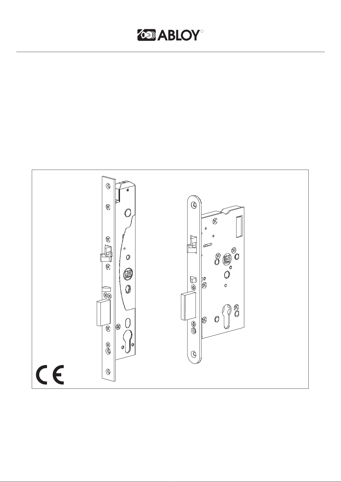
Profile door locks ABLOY®
DO 20.33.01
DO 20.33.02
IKON
DO 20.15.02
FSB
DO 20.03.01,
DO 20.03.02
HEWI
DO 20.13.01,
DO 20.13.02
SAPEX
DO 20.32.01
DO 20.32.02
EL420
EL422
e.g. ABLOY® INOXI
3-19/013/120 PZ+BL
e.g. S6B8 1016, 1023, 1056, 1070, 1080,
1088, 1090, 1117, 1118, 1119,
1137, 1146, 1155, 1160, 1161,
1162, 1177, 1178, 1191, 0612,
0616, 0617, 0619, 0625, 0627,
0628, 0646, 0662, 0665, 0680,
0681, 0682, 0688
111, 111.23,
114.23GK,
131, 132, 111X,
113X, 114X, 161X,
163X, 171X, 112X,
165X, 166X
e.g. 60-0719
Wooden and metal
door locks ABLOY®
DO 20.33.01
DO 20.33.02
IKON
DO 20.15.02 SAPEX
DO 20.32.01
DO 20.32.02
EL520
EL522
e.g. ABLOY® INOXI
3-19/012/120 PZ+BL
e.g. S4K6 e.g. 60-0119
Functional check after installation:
Emergency exit (active) side and functional sensitivity tests:
- Use the handle of exit side.
- In the profile door locks the force of handle is about 15 N (approximately 1.5 kg weight at a
100 mm distance from the pivot of the handle opens the lock).
- In the wooden door locks the force of handle is about 15 N (approximately 1.5 kg weight
at a 100 mm distance from the pivot of the handle opens the lock). According to EN 179 the
force of handle must be less than 70 N.
- Close the door slowly and check that the lock deadlocks.
- Check that the bolts slide freely into the strike plate.
The safety features of this product are essential to its compliance with EN 179. No modifica-
tion of any kind, other than those described in these instrictions, are permitted.
PANIC EXIT DEVICES INSTALLATION ACCORDING TO EN 1125
The following locks and push bars are approved to be installed together on the panic exit door.
Strike plate EA321, EA322, EA323, EA324, EA325, EA326, EA327, EA328, EA329, EA330,
EA331, EA332 must be used in the installation.
Profile door locks effeff
DO 30.04 JPM
DO 30.05
TESA
DO 30.06
EL420 8000-00-1100 (-), 8000-10-1100 (PZ) NORMA
990000-XX-0A, 990100-XX-0A,
990001-XX-0A, 990101-XX-0A,
991000-XX-0A, 991100-XX-0A,
991001-XX-0A, 991101-XX-0A
UNIVERSAL
SERIE
19709G9xx
EL422 8000-00-1100 (-), 8000-11-1100 (RZ)
Wooden and
metal door locks effeff
DO 30.04
EL520 8000-00-1100 (-), 8000-20-1100 (PZ)
EL522 8000-00-1100 (-), 8000-21-1100 (RZ)
Functional check after installation:
Panic exit (active) side and functional sensitivity tests:
- Push the push bar towards the door on the exit side.
- Force to open the lock by pushing the bar is about 60 N (approximately 6kg). According
to EN 1125 it must be less than 80 N.
- Close the door slowly and check that the lock deadlocks.
- Check that the bolts slide freely into the strike plate.
Note! The length ot the push bar must be at least 60 % of the width of the door.
The safety features of this product are essential to its compliance with EN 1125. No modifi-
cation of any kind, other than those described in these instrictions, are permitted.
Recommended distance from a floor to a handle or to a push bar is between
900mm - 1100mm.
Lubricate the bolts of the lock case at least once a year. Use vaseline type lubrication.
Note! Abloy Oy will not be liable for products in case these instructions are not followed.
6
!
!

R
WIRING DIAGRAM
EL420, EL422, EL520, EL522
12 - 24 V DC +/-15%
12 - 18 V AC -10%/+15%, RMS
Red
Black
External connection
for Backup-card
Connection cable ABLOY
EA218 / EA219
Length 6 m/ 10m
18 x 0.14 mm2
Potential free
control
Relays of control unit when:
- Door closed
- Handle not used
- Key cylinder not used
- Bolt not in
- Bolt out
Monitoring cable
sabotage loop *)
*) Potential free loop is closed
when connection cable is con-
nected to lockcase.
Copyright© Abloy Oy Joensuu Factory
R
7
Monitoring
Potential free relay contacts

R
SETTABLE FUNCTIONS OF EL420 ENGLISH
CHANGING THE FOREND Fig. A
1. Set the lock case forend up on the table.
2. Unscrew the fixing screws and remove the forend. Please note that the double action
bolt and its two bushings do not fall off.
3. Set another forend and screw in the screws. Use LOCTITE 243 on each fixing screw.
REMOVING THE MANIPULATION PROTECTION COVER Fig. B
CHANGING THE HANDING OF THE TRIGGER BOLT Fig. C (Needed tool: 2.5 mm Allen key)
1. Locate the Allen key between the two springs in the back of the lock case in the Allen
screw-head of the trigger bolt (Fig. C1).
2. Loosen the Allen screw, so that the trigger bolt moves forward and can be turned around
(Fig. C2). Please note not to unscrew the Allen screw.
3. When the handing of the trigger bolt is set, tighten the Allen screw (Fig. C3).
When the handing has been changed, attach the manipulation protection cover.
ATTACHING THE CABLE Fig. D
1. Unscrew the fixing screw and remove the cable clamp.
2. Connect the cable into the connector. Fix the cable clamp.
SETTING 8/9 SNAP SPINDLE ADAPTERS Fig. H
8/9 snap spindle adapters are set if the lock case is installed with 8mm spindle. The adapters
must be set on the both sides of the lock case.
There are two flat sides and two sides with a cup in an adapter. The round markings on the
handle follower of a lock case denote the direction, in which the adapter is set. With the mo-
tor locks the direction of the adapter has to be noticed!
SETTABLE FUNCTIONS OF EL520
CHANGING THE FOREND Fig. E
1. Unscrew the fixing screws and remove the forend.
2. Set another forend and screw in the fixing screws. Please note that a screw below the
dead bolt is longer than the other screws. Use LOCTITE 243 on each fixing screw.
CHANGING THE HANDING OF THE TRIGGER BOLT Fig. F (Needed tool: 2 mm Allen key)
1. Press the trigger bolt inside the lock case until the Allen screw of the trigger bolt is
shown on the cover side of the lock case.
2. Unscrew the Allen screw.
3. Pull out the trigger bolt and turn it around.
4. Put the trigger bolt back in its place and press it inside the lock case.
5. Screw in the Allen screw.
ATTACHING THE CABLE Fig. G
1. Connect the cable in the connector.
2. Use a cable tie to fix the cable to the lock case. Cut the cable tie short.
SETTING 8/9 SNAP SPINDLE ADAPTERS Fig. H
8

R
TECHNISCHE DATEN DEUTSCH
Spannung: 12 - 24 V DC (± 15%)
12 - 18 V AC (-10%/+15%)
Strom: 12 V DC 80 mA Ruhestrom
450 mA Normalbetrieb
1300 mA Anlaufspitzenstrom
24 V DC 40 mA Ruhestrom
220 mA Normalbetrieb
600 mA Anlaufspitzenstrom
Ausgänge Mikroschalter max. 0.8 A 30 V AC/DC resist. 20 W
Betriebstemperatur: -20°C bis +60°C
Riegel: rechteckig, Hub 20 mm, Kreuzfalle, Hub 10 mm
Dornmaße: 55, 60, 65, 80, 100 mm (EL520, EL522)
30, 35, 40, 45 mm (EL420, EL422)
Stulpblech: 20, 24 mm (EL520)
24, 28 mm (EL420)
Drückernuss: 9 mm (8 mm mit Adapter)
Anschlusskabe: EA218 (6 m) / EA219 (10 m) 18 x 0.14 mm2
Riegel-Rückhaltezeit: 2 - 15 s
Abstand Türe/Zarge 2 – 5.5 mm (Zwischen Stulp und Schließleche)
Einstellbare Funktionen: Mechanische:
-Einstellung der Steuerfalle (rechte linke Türe)
Überwachung der Ausgänge: Riegel ausgefahren
Türe geschlossen
Steuerfalle gedrückt
Drücker betätigt
Schließzylinder betätigt
Sabotage
Schließbleche: EA321, EA322, EA323, EA324, EA325, EA326, EA327,
EA328, EA329, EA330, EA331, EA332
DIE SCHLÖSSER ENTSPRECHEN VOLLGENDEN STANDARDS
EN STANDARDS
EN 179
EN 1125
EN 1634-1
3 7 6 1 1 3 2 2
A
3 7 6 1 1 3 2 1/2 A Notausgänge
Anti-Paniktüren
Feuerschutztüren
EN
61000
-
6
-
1
:
2007
EMC
EN 61000-6-3:2007 EMC
9

R
INSTALLATION FÜR NOTAUSGÄNGE ENTSPRECHEND EN 179
Die folgenden Schlösser, Beschläge und Schließbleche (EA321, EA322, EA323, EA324,
EA325, EA326, EA327, EA328, EA329, EA330, EA331, EA332) müssen als Set eingebaut
werden, um der Norm EN 179 zu entsprechen.
Schlösser für
Profiltüren
ABLOY®
DO 20.33.01
DO 20.33.02
IKON
DO 20.15.02
FSB
DO 20.03.01,
DO 20.03.02
HEWI
DO 20.13.01,
DO 20.13.02
SAPEX
DO 20.32.01
DO 20.32.02
EL420
EL422 e.g. ABLOY® INOXI
3-19/013/120 PZ+BL
e.g. S6B8 1016, 1023, 1056, 1070, 1080,
1088, 1090, 1117, 1118, 1119,
1137, 1146, 1155, 1160, 1161,
1162, 1177, 1178, 1191, 0612,
0616, 0617, 0619, 0625, 0627,
0628, 0646, 0662, 0665, 0680,
0681, 0682, 0688
111, 111.23,
114.23GK,
131, 132, 111X,
113X, 114X, 161X,
163X, 171X, 112X,
165X, 166X
e.g. 60-0719
Schlösser für
Holztüren
ABLOY®
DO 20.33.01
DO 20.33.02
IKON
DO 20.15.02 SAPEX
DO 20.32.01
DO 20.32.02
EL520
EL522
e.g. ABLOY® INOXI
3-19/012/120 PZ+BL
e.g. S4K6 e.g. 60-0119
Funktionsprüfung nach der Installation
Notausgangs- und Funktionsempfindlichkeitstest:
- Benutzen Sie den Drücker der Panikseite.
- Bei Schlössern in Profiltüren ist der Kraftaufwand zum Öffnen des Schlosses ungefähr
15 N (ca. 1,5 Kilogramm bei 100 mm Hebelänge)
- Bei Schlössern in Holztüren ist der Kraftaufwand ungefähr 15 N (ca. 1,5 Kilogramm bei
100 mm Hebelänge). Entsprechend der Norm EN 179 muss dieser Kraftaufwand kleiner als
70 N sein.
- Schließen Sie die Türe langsam und prüfen Sie, ob das Schloss ordnungsgemäß ver-
schließt.
- Prüfen Sie, ob der Riegel und die Falle ungehindert in das Schließblech einrasten können.
Die Sicherheitsmerkmale des vorliegenden Produktes sind für die Übereinstimmung mit EN
179 wesentlich. Mit Ausnahme der in dieser Anleitung beschriebenen Änderungen, sind
keine weiteren Änderungen jeder Art zulässig.
INSTALLATION FÜR ANTI-PANIK-AUSGÄNGE ENTSPRECHEND EN 1125
Die folgenden Schlösser, Stangengriffe/Druckstangen und Schließbleche (EA321, EA322,
EA323, EA324, EA325, EA326, EA327, EA328, EA329, EA330, EA331, EA332) müssen als Set
eingebaut werden um der Norm EN 1125 zu entsprechen.
Schlösser für
Profiltüren effeff
DO 30.04 JPM
DO 30.05
TESA
DO 30.06
EL420 8000-00-1100 (-), 8000-10-1100 (PZ) NORMA
990000-XX-0A, 990100-XX-0A,
990001-XX-0A, 990101-XX-0A,
991000-XX-0A, 991100-XX-0A,
991001-XX-0A, 991101-XX-0A
UNIVERSAL
SERIE
19709G9xx
EL422 8000-00-1100 (-), 8000-11-1100 (RZ)
Schlösser für
Holztüren
effeff
DO 30.04
EL520
8000
-
00
-
1100
(
-
)
,
8000
-
20
-
1100
(PZ)
EL522 8000-00-1100 (-), 8000-21-1100 (RZ)
Funktionsprüfung nach der Installation
Antipanikausgangs- und Funktionsempfindlichkeitstest:
- Benutzen Sie den Stangengriff/Druckstange der Panikseite.
- Bei Schlössern ist der Kraftaufwand zum Öffnen des Schlosses ungefähr 60 N (ca. 6 Kilo-
gramm). Entsprechend der Norm EN 1125 muss dieser Kraftaufwand kleiner als 80 N sein.
- Schließen Sie die Türe langsam und prüfen Sie, ob das Schloss ordnungsgemäß versch
ließt.
- Prüfen Sie, ob der Riegel und die Falle ungehindert in das Schließblech einrasten können.
Anmerkung! Die Länge des Stangengriffes/Druckstange muss mindestens 60% der Türbreite
betragen.
Die Sicherheitsmerkmale des vorliegenden Produktes sind für die Übereinstimmung mit EN
1125 wesentlich. Mit Ausnahme der in dieser Anleitung beschriebenen Änderungen, sind
keine weiteren Änderungen jeder Art zulässig.
10
!
!

R
Empfohlener Abstand vom Fußboden zum Stangengriff/Druckstange ist zwischen
900 mm - 1100 mm.
Schmieren Sie die Schraubbolzen des Verriegelungskastens mindestens einmal im Jahr.
Achtung! Die Firma Abloy Oy haftet nicht für Produkte bei denen diese Anweisungen
nicht ordnungsgemäß befolgt wurden.
11

R
ANSCHLUßSCHEMA
EL420, EL422, EL520, EL522
12 - 24V DC +/-15%
12 - 18V AC -10%/+15%, RMS
Rot
Schwarz
Externer Anschluss
für Backup-card
TÜR WEISS
SCHWARZ+VIOLETT
GRÜN
DRÜCKER
ZYLINDER
RIEGEL
eingefahren
RIEGEL
ausgefahren
GELB
ROT
BRAUN
BLAU
ROT/GRÜN
ORANGE
TÜRKIS
GRAU
PINK
Anschlusskabel ABLOY
EA218 / EA219
Länge 6 m/10 m
18 x 0.14 mm2
potentionalfreier
Öffnungskontakt
ÖFFNUNG
RESERVE
GND
Ausgänge externe Steuerung:
- Türe geschlossen
- Drücker nicht betätigt
- Schließzylinder nicht betätigt
- Riegel eingefahren
- Riegel ausgefahren
Sabotage Schlaufe*)
*) Potentionalfreier Kontakt ist ge-
schlossen wenn der Anschlusssteck-
er am Schloss angesteckt ist.
Copyright© Abloy Oy Joensuu Factory
R
12
Überwachung
Potentionalfreie Relaiskontakte

R
EINSTELLBARE FUNKTIONEN FÜR EL420 DEUTSCH
MONTAGE- UND DEMONTAGE DES STULPBLECHES Fig. A
1. Stellen Sie das Schloss so hin, dass das Stulpblech oben ist.
2. Entfernen Sie die Schrauben und nehmen Sie das Stulpblech vom Schloss. Achten Sie
darauf, dass die Kreuzfalle und die beiden Buchsen nicht herunterfallen.
3. Geben Sie ein anderes Stulpblech aufs Schloss und befestigen Sie es wieder mit den da-
zugehörigen Schrauben. Benutzen Sie LOCTITE 243 um jede Schraube zu sichern.
ENTFERNEN DER SCHUTZ-ABDECKUNG Fig. B
ÄNDERN DER STEUERFALLEN POS. (rechte/linke Türe) Fig. C
(erforderliches Werkzeug: 2,5 mm Inbusschlüssel)
1. Stecken Sie den Inbusschlüssel auf der Rückseite des Schlosses zwischen den beiden
Federn in den Steuerfallen Bolzen (Fig. C1).
2. Lösen Sie die Inbusschraube, damit der Steuerfallenbolzen vorwärts bewegt und herum
gedreht werden kann (Fig. C2). Bitte beachten Sie, dass Sie die Inbusschraube nicht ganz
herausdrehen.
3. Wenn die Steuerfalle wieder richtig positioniert ist, kann man die Inbusschraube wieder
est anziehen. (Fig. C3).
Wenn die neue Positionierung der Steuerfalle durchgeführt ist, bringen Sie die Schutzab-
deckung wieder an.
BEFESTIGUNG DES ANSCHLUSSKABELS Fig. D1
1. Entfernen Sie die Schraube und die Kabelschelle.
2. Stecken Sie das Anschlusskabel in die vorgesehenen Anschlussbuchse und montieren
Sie die Kabelschelle wieder.
EINBAU DES ADAPTERS FÜR 8 mm DRÜCKERNUSS Fig. H
Die Adapter für die Drückernuss (9 mm auf 8 mm) müssen eingebaut werden, wenn man
eine 8 mm Drückernuss benötigt. Diese Adapter müssen auf beiden Seiten des Schlosses
montiert werden.
Es gibt zwei flache Seiten und zwei Seiten mit einer Schale im Adapter. Die runden Marki-
erungen auf der Drückernuss des Schlosses legen fest, wie der Adapter eingesetzt werden
muss. Bei der Verwendung der Adapter mit Motorschlössern ist die Richtung zu beachten.
EINSTELLBARE FUNKTIONEN FÜR EL520
MONTAGE UND DEMONTAGE DES STULPBLECHES Fig. E
1. Stellen Sie das Schloss so hin, dass das Stulpblech oben ist.
2. Entfernen Sie die Schrauben und nehmen Sie das Stulpblech vom Schloss.
3. Geben Sie ein anderes Stulpblech aufs Schloss und befestigen Sie es wieder mit den da-
zugehörigen Schrauben. Benutzen Sie LOCTITE 243 um jede Schraube zu sichern.
ÄNDERN DER STEUERFALLEN POS. (rechte/linke Türe) Fig. F
(erforderliches Werkzeug: 2 mm Inbusschlüssel)
1. Drücken Sie die Steuerfalle in den Schlosskasten, bis die Inbusschraube auf der Schloss-
seite zu sehen ist.
2. Schrauben Sie die Inbusschraube auf und nehmen Sie diese aus dem Schlosskasten.
3. Nehmen Sie die Steuerfalle aus dem Schlosskasten und drehen Sie diese um 180° in die
gewünschte Position.
4. Setzen Sie die Steuerfalle in den Schlosskasten wieder ein.
5. Schrauben Sie die Inbusschraube wieder fest.
BEFESTIGUNG DES ANSCHLUSSKABELS Fig. G
1. Stecken Sie das Anschlusskabel in die vorgesehenen Anschlussbuchse.
2. Benutzen Sie einen Kabelbinder, um das Anschlusskabel am Schlosskasten zu befesti-
gen. Entfernen Sie den restlichen Kabelbinder
EINBAU DES ADAPTERS FÜR 8 mm DRÜCKERNUSS Fig. H
13

DETAILS TECHNIQUES FRANCAIS
Tension d’exploitation : 12 - 24 V DC (± 15 %)
12 - 18 V AC (-10 % / 15 %), RMS
Consommation : 12 V DC 80 mA repos
450 mA
1300 mA maxi.
24 V DC 40 mA repos
220 mA
600 mA maxi.
Sorties pour télésurveillance : maximum 0.8 A 30V AC/DC résistance, 20 W
Température d’exploitation : -20°C - +60°C
Saillies des pênes : 20 mm (pêne dormant), 10 mm (pêne double action)
Entraxe : 55, 60, 65, 80, 100 mm (EL520, EL522)
30, 35, 40, 45 mm (EL420, EL422)
Têtière : 20, 24 mm (EL520, EL522)
24, 28 mm (EL420, EL422)
Carré : 9 mm (8 mm avec fourreau d’adaptation)
Câble de connexion: EA218 (6 m) / EA219 (10 m) 18x 0.14 mm2
Temporisation: 2 - 15 s
Dégagement de la porte: 2 - 5.5 mm
Fonctions ajustables : Fonctions mécaniques :
- Sens d’ouverture du contre pêne
Sorties pour télésurveillance : Pêne verrouillé
Serrure ouverte
Contre pêne rentré
Béquille abaissée
Cylindre utilisé
Sabotage
Gâches : EA321, EA322, EA323, EA324, EA325, EA326, EA327,
EA328, EA329, EA330, EA331, EA332
TESTS SELON LES NORMES
EN STANDARDS
EN 179 3 7 6 1 1 3 2 2
A
Sortie d’urgence
EN
1125
3
7
6
1
1
3
2
1/2
A
I
ssue
d
e secours
EN
1634
-
1
Ré
s
i
s
t
ance au
F
eu
EN
61000
-
6
-
1
:
2007
EMC
EN 61000-6-3:2007 EMC
14
R

R
INSTALLATION DE DISPOSITIFS DE SORTIE D’URGENCE SELON LA
NORME EN 179
Les serrures et béquilles suivantes peuvent être installées ensemble sur une porte de sortie de
secours. Les gâches EA321, EA322, EA323, EA324, EA325, EA326, EA327, EA328, EA329,
EA330, EA331, EA332 doivent être utilisées dans l’installation.
Serrures pour
portes à profi
ABLOY®
DO 20.33.01
DO 20.33.02
IKON
DO 20.15.02
FSB
DO 20.03.01,
DO 20.03.02
HEWI
DO 20.13.01,
DO 20.13.02
SAPEX
DO 20.32.01
DO 20.32.02
EL420
EL422
e.g. ABLOY® INOXI
3-19/013/120 PZ+BL
e.g. S6B8 1016, 1023, 1056, 1070, 1080,
1088, 1090, 1117, 1118, 1119,
1137, 1146, 1155, 1160, 1161,
1162, 1177, 1178, 1191, 0612,
0616, 0617, 0619, 0625, 0627,
0628, 0646, 0662, 0665, 0680,
0681, 0682, 0688
111, 111.23,
114.23GK,
131, 132, 111X,
113X, 114X, 161X,
163X, 171X, 112X,
165X, 166X
e.g. 60-0719
Serrures pour
portes en bois
ABLOY®
DO 20.33.01
DO 20.33.02
IKON
DO 20.15.02 SAPEX
DO 20.32.01
DO 20.32.02
EL520
EL522 e.g. ABLOY® INOXI
3-19/012/120 PZ+BL
e.g. S4K6 e.g. 60-0119
Vérification du fonctionnement après installation:
Tests côté sortie libre (actif) et tests de sensibilité de fonctionnement :
- Utiliser la béquille de sortie.
- Dans les serrures pour porte à profil, la force de la béquille est d’environ 15 N (un poids
d’environ 1.5 kg à une distance de 100 mm de l’axe de rotation de la béquille ouvrant la ser-
rure).
- Dans les serrures pour porte bois, la force de la béquille est d’environ 15 N (un poids
d’environ 1.5 kg à une distance de 100 mm de l’axe de rotation de la béquille ouvrant la ser-
rure). Selon la norme EN 179, la force de la béquille doit être inférieure à 70 N.
- Fermer la porte lentement et vérifier que la serrure se verrouille.
- Vérifier que le pêne glisse à l’intérieur de la gâche.
Les caractéristiques de sécurité de ce produit sont essentielles pour sa conformité avec la
norme EN 179. Aucune modifications quelles qu’elles soient ne sont permises, sauf celles
décrites dans ces instructions.
INSTALLATION DES DISPOSITIFS D’ISSUE DE SECOURS SELON LA
NORME EN 1125
Les serrures et les barres suivantes peuvent être installées ensemble sur une porte d’issue de
secours. Les gâches EA321, EA322, EA323, EA324, EA325, EA326, EA327, EA328, EA329,
EA330, EA331, EA332 doivent être utilisées dans cette installation.
Serrures pour
portes à profi effeff
DO 30.04 JPM
DO 30.05
TESA
DO 30.06
EL420 8000-00-1100 (-), 8000-10-1100 (PZ) NORMA
990000-XX-0A, 990100-XX-0A,
990001-XX-0A, 990101-XX-0A,
991000-XX-0A, 991100-XX-0A,
991001-XX-0A, 991101-XX-0A
UNIVERSAL
SERIE
19709G9xx
EL422 8000-00-1100 (-), 8000-11-1100 (RZ)
S
errures pour
portes en bois effeff
DO 30.04
EL520 8000-00-1100 (-), 8000-20-1100 (PZ)
EL522 8000-00-1100 (-), 8000-21-1100 (RZ)
Vérification du fonctionnement après installation:
Tests côté sortie libre et tests de fonctionnement :
- Pousser la barre vers la porte côté sortie
- Ouvrir la serrure en poussant la barre d’environ 60 N (environ 6Kg). Selon la norme
EN 1125, elle doit être inférieure à 80 N.
- Fermer lentement la porte et vérifier que la serrure se verrouille.
- Vérifier que les pênes glissent librement à l’intérieur de la gâche.
Noter que la longueur de la barre doit représenter au moins 60 % de la largeur de la porte !
Les caractéristiques de sécurité de ce produit sont essentielles pour sa conformité avec la
norme EN 1125. Aucune modifications quelles qu’elles soient ne sont permises, sauf celles
décrites dans ces instructions.
La distance recommandée du sol à une béquille ou à une barre est entre
900 mm - 1100 mm.
Lubrifier les pênes de la serrure au moins une fois par an. Utiliser de la vaseline comme
lubrifiant.
Noter que ABLOY Oy décline toute responsabilité en cas de non respect de ces recom-
mandations. 15
!
!

R
SCHEMA DE CABLAGE
EL420, EL422, EL520, EL522
12 - 24 V DC +/-15%
12 - 18 V AC -10%/+15%, RMS
OUVERT
PORTE
FERME
UTILISE
BEQUILLE
NON UTILISE
UTILISE
CYLINDRE
NON UTILISE
PÊNE RENTRE
PÊNE SORTI
ROUGE
NOIR
BLANC
NOIR+VIOLET
VERT
JAUNE
ROUGE
MARRON
BLEU
ROUGE/VERT
ORANGE
TURQUOISE
GRIS
ROSE
Connexion externe pour
carte de sauvegarde
Câble de connexion
ABLOY EA218 / EA219
Longueur 6 m/10 m
18 x 0.14 mm2
Contrôle
d’ouverture
OUVER-
TURE
A la terre
Informations de télésurveillance :
- Porte fermée
- Béquille non abaissée
- Clé du cylindre non utilisée
- Pêne rentré
- Pêne sorti
Boucle de sabotage du
câble de contrôle *)
*) Le circuit électrique est fermé
quand le câble de connexion est con-
necté au boîtier de serrure.
Copyright© Abloy Oy Joensuu Factory
R
16
Contrôle
Contacts de télésurveillance

R
FONCTIONS AJUSTABLES DE LA EL420 FRANCAIS
CHANGEMENT DE LA TETIERE fig. A
1. Mettre la serrure sur la table la têtière vers le haut.
2. Dévisser les vis de fixation et enlever la têtière. Attention à ce que le pêne double action
ne tombe pas.
3. Installer une autre têtière et visser les vis. Utiliser de la LOCTITE 243 sur chaque vis de
fixation.
ENLEVEMENT DU COUVERCLE DE PROTECTION fig. B
CHANGEMENT DE SENS DU CONTRE PENE Fig. C
(outil nécessaire : clé Allen de 2.5 mm)
1. Placer la clé Allen entre les deux ressorts à l’arrière du boîtier de la serrure dans la vis du
contre pêne (fig. C1).
2. Desserrer la vis Allen pour que le contre pêne avance et puisse être retourné
(fig. C2). Attention à ne pas dévisser complètement la vis Allen.
3. Quand le sens du contre pêne est modifié, serrer la vis Allen (fig. C3).
Quand le changement de sens a été fait, remettre le couvercle de protection.
FIXATION DU CABLE fig.D
1. Dévisser les vis de fixation et enlever l’attache du câble.
2. Brancher le câble aux connecteurs. Fixer l’attache du câble.
INSTALLATION DES FOURREAUX D’ADAPTATION 8/9 mm Fig. H
Les fourreaux d’adaptation 8/9 mm sont utilisés si la serrure est installée avec un carré de 8
mm. Les adaptateurs doivent être mis sur les deux côtés de la serrure.
Il y a deux côtés plats et deux côtés incurvés dans l’adaptateur. Les indications rondes sur
le fouillot de la serrure indiquent le sens dans lequel l’adaptateur doit être placé. Le sens de
l’adaptateur a de l’importance avec les serrures motorisées.
FONCTIONS DE LA EL520
CHANGEMENT DE LA TETIERE Fig. E
1. Dévisser les vis de fixation et enlever la têtière.
2. Mettre une autre têtière et la visser dans les vis de fixation. Noter que la vis en dessous
du pêne dormant est plus longue que les autres vis. Utiliser de la LOCTITE 243 sur chaque
vis de fixation.
CHANGEMENT DE SENS DU CONTRE PENE Fig. F (outil nécessaire : clé Allen de 2 mm).
1. Rentrer le contre pêne dans la serrure jusqu’à ce que l’on voit la vis Allen du contre-
pêne sur le couvercle de la serrure.
2. Dévisser la vis Allen.
3. Retirer le contre pêne et le retourner.
4. Replacer le contre pêne à sa place et l’enfoncer à l’intérieur de la serrure.
5. Visser dans la vis Allen.
FIXATION DU CABLE Fig. G
1. Brancher le câble aux connecteurs.
2. Utiliser une attache pour fixer le câble à la serrure. Raccourcir l’attache.
INSTALLATION DES FOURREAUX D’ADAPTATION 8/9 mm Fig. H
17

TECHNISCHE SPECIFICATIES NEDERLANDS
Aansluitspanning: 12-24 V DC ( 15%)
12-18 V AC (-10% / +15%), RMS
Stroomafname: 12 V DC 80 mA in rust
450 mA motor in bedrijf
1300 mA maximaal.
Max 24 V DC 40 mA in rust
220 mA motor in bedrijf
600 mA maximaal.
Maximale belasting: Max. 0,8 A 30 V AC/DC, 20 W
Bedrijfstemperatuur: -20°C - +60°C
Schootuitslag: 20 mm (nachtschoot), 10 mm (tweedelige dachtschoot)
Doornmaat: 55, 60, 65, 80, 100 mm (EL520, EL522)
30, 35, 40, 45 mm (EL420, EL422)
Voorplaat: 20, 24 mm (EL 520, EL522)
24, 28 mm (EL420, EL422)
Krukgat: 9 mm (8 mm met krukadaptor)
Aansluitkabel: EA218 (6 m) / EA219 (10 m) 18 x 0.14 mm2
Instelbare tijdsvertraging: 2 - 15 s
Sluitnaat: 2 – 5.5 mm
Aanpasbare functies: Mechanische functies:
- Aanpassen draairichting dmv trigger bolt
Uitgangssignalen: Schoot uit / schoot in
Slot open / Slot niet open
Trigger bolt in
Kruk neer
Cilinder in gebruik
Sabotage
Sluitplaat: EA321, EA322, EA323, EA324, EA325, EA326, EA327, EA328,
EA329, EA330, EA331, EA332
Het gebruik van bouwsleutels is niet toegestaan omdat hiermee het slot ernstig beschadigd
kan raken.
GOEDGEKEURD VOLGENS DE VOLGENDE EN-NORMEN
EN NORMEN
EN 179 3 7 6 1 1 3 2 2
A
Nooddeuren
EN
1125
3
7
6
1
1
3
2
1/2
A
P
an
i
e
kd
euren
EN
1634
-
1
B
ran
d
EN
61000
-
6
-
1
:
2007
EMC
EN 61000-6-3:2007 EMC
18
R
!
Other manuals for CERTA EL420
1
This manual suits for next models
3
Table of contents
Languages:
Other Abloy Lock manuals