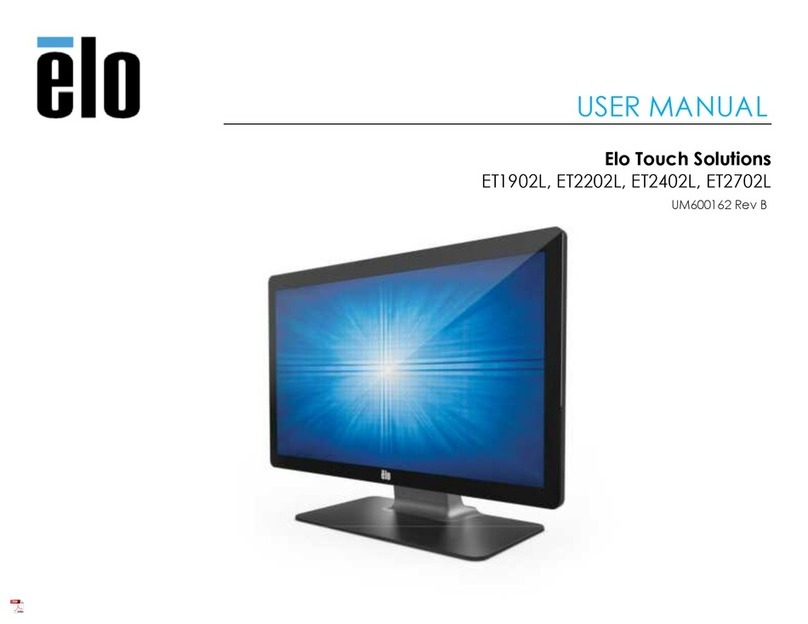
Seypos TM Series User manual

User’s Manual
Touch Screen Monitor
Model: TM-15"/17"/19"/22"W
Version 2.0 2010.10

2
Disclaimer
The information in this document is subject to change without notice. Seypos company
makes no representations or warranties with respect to the contents hereof, and
specifically disclaims any implied warranties of merchantability or fitness for a particular
purpose. Seypos reserves the right to revise this publication and to make changes from
time to time in the content hereof without obligation of Seypos to notify any person of such
revisions or changes.

3
Warnings and Cautions
Warning
•Danger —Explosion hazard. Do not use in the presence of flammable
anesthetics.
•To prevent fire or shock hazards, do not immerse the unit in water or expose it
to rain or moisture.
•Do not use the unit with an extension cord receptacle or other outlets unless
the prongs of the power cord can be fully inserted.
•RISK OF ELECTRICAL SHOCK —DO NOT OPEN. To reduce the risk of electrical
shock, DO NOT remove the back of the equipment or open the enclosure. No user‐
serviceable parts are inside. Refer servicing to qualified field service engineers only.
•Uninsulated voltage within the unit may have sufficient magnitude to cause
electrical shock. Avoid contact with any part inside the unit.
Caution
•Before connecting the cables to your Elo TouchSystems touchmonitor, make sure
all components are powered OFF.
•The use of ACCESSORY equipment not complying with the equivalent safety
requirements of this equipment may lead to a reduced safety of the resulting
system. Consideration relating to the choices of accessory equipment should
include:
•Use of accessory in the patient vicinity.
•Evidence that the safety certification of the accessory has been performed in
accordance to the appropriate IEC 60601‐1 and/or IEC 60601‐1‐1 harmonized
national standard.
•For continued safety —
‐ This unit only complies to the above standards if used with a medical grade
power cord.
‐ A medical grade power adaptor, such as the one specified, is required for use
in a medical application. Note:
•This symbol alerts the user to important information concerning the operation and
maintenance of this unit, which should be read carefully to avoid problems.
CAUTION‐Life Support
Care must be taken when this touchmonitor is a critical component of a Life
support system or device. In case of failure of this touchmonitor, appropriate redundant
systems should be incorporated into the system or device to prevent injury to the user
or patient.
The following should be an integral part of the safety design of a Life support system
or device using this touchmonitor for a critical function.
♦An Alternate interface or fail‐safe must be available should the touchscreen fail to
operate.
♦The touchscreen interface must not be the only means of control of a critical
function.
♦An Alternate video monitor should be incorporated into the safety design if used
to monitor a critical function.
♦The internal speakers of this touchmonitor must not be the sole method of warning
of a critical function.

4
Critical functions are:
1. Life support devices or systems are devices or systems which, (a) are intended for
surgical implant into the body, or (b) support or sustain life, or (c) whose failure
to perform when properly used in accordance with instructions for use provided
in the labeling, can be reasonably expected to result in significant injury to the
user.
2. A critical component is any component of a life support device or system whose
failure to perform can be reasonably expected to cause the failure of the life
support device or system, or to affect its safety or effectiveness.

5
Table of Contents
INTRODUCTION ................................................................. ..................... ................... 7
Product Description ....................................................................................................... 7
LCD Monitor Performance Features ............................................................................. 7
TFT LCD Monitor Panel......................................................... .................................. 7
External Medical Grade Power Adaptor..................................................................... 7
INSTALLATION AND SETUP ......................................... ..... ..................................... 8
Unpacking Your Touchmonitor...................................................................................... 8
Product Overview .......................................................................................................... 8
Front View ........................................................................................ .........................9
Rear View ................................................................................................................ 10
Side View...................................................................................... ............................10
KensingtonTM Lock................................................................ .................................... 11
USB Interface Connection ........................................................................................... 11
Replace the Cable Cover............................................................................................... 13
Optimizing the LCD Monitor ...................................................................................... 14
Installing the Touch Driver Software .......................................................................... 14
Installing the USB Touch Driver ................................................................................. 15
Installing the USB Touch Driver for Windows XP... ............................ ................ 16
OPERATION............................................................................ ..................................... 17
About Touchmonitor Adjustments .............................................................................. 17
Controls and Adjustment ............................................................................................. 17
OSD Lock/Unlock ................................................................................................... 17
Power Lock/Unlock ................................................................................................. 18
OSD Menu Functions .............................................................................................. 18
OSD Control Options (Clockwise) .......................................................................... 18
Power LED Monitor & Power Saving.......................................................................... 18
General Power Saving Mode ................................................................................... 18
Monitor Angle (desktop only) ..................................................................................... 19
TROUBLESHOOTING..................................................... ........................................... 20
Solutions to Common Problems ...................................................................................... 20
NATIVE RESOLUTION .............................................. .......... .................................... 21
TOUCHMONITOR SAFETY...................................... ................................................ 22
Care and Handling of Your Touchmonitor................................................................... 22
TECHNICAL SPECIFICATIONS............................ ................................................... 22
Touchmonitor Specifications ....................................................................................... 23
REPLACEMENT PARTS..............................................................................................30
Replacement Parts......................................................................................................... 30
WARRANTY ........................................... ........ ............................................................. 31
CHAPTER

6
1
INTRODUCTION
Product Description
The T06 series touch screen monitors which use liquid crystal monitor (LCD) technology,
designed to present information to the operator, care-giver and the patient. The T06 series
features both serial and USB touch interfaces as standard configuration. The T06 series
functionally consists of 15/17/17/22 inch LCD main monitor with a touch screen. The
monitors element is a 15.0 inch diagonal XGA resolution (1024x768) LCD monitor, 17
inch diagonal XGA resolution 1280x1024 LCD monitor, and 22 inch diagonal WXGA
resolution (1680x1050) wide screen LCD monitor.Three types of touchscreen technology
are offered for the T06 series as Resistive touch screen technology. The T06 series are
powered by 12V DC from an external industrial power adapter.
LCD Monitor Performance Features
15 inch TFT LCD Monitor Panel
Monitor format 1024x768
Monitor area 304.1 mm (H) x 228 mm (V)
Pixel pitch 0.297 mm (H) x 0.297 mm (V
Contrast ratio 600:1 typical
Brightness LCD 250 cd/m2 (Typical)
Response time 14.2 msec typical
Monitor color 16.7 million colors, 6 Bit with dithering
Typical vertical viewing angle: 85 deg (looking down) / 85 deg (looking up)
Typical horizontal viewing angle: 85 deg (looking left) / 85 deg (looking right)
17 inch TFT LCD Monitor Panel
Monitor format 1280x1024
Monitor area 338 mm (H) x 270 mm (V)
Pixel pitch 0.264 mm (H) x 0.264 mm (V
Contrast ratio 1000:1 typical
Brightness LCD 250 cd/m2 (Typical)
Response time 5 msec typical
Monitor color 16.7 million colors, 6 Bit with dithering
Typical vertical viewing angle: 80 deg (looking down) / 80 deg (looking up)
Typical horizontal viewing angle: 80 deg (looking left) / 80 deg (looking right)

7
19 inch TFT LCD Monitor Panel
Monitor area 376 mm (H) x 301 mm (V)
Pixel pitch 0.294 mm (H) x 0.294 mm (V
Contrast ratio 1000:1 typical
Brightness LCD 250 cd/m2 (Typical)
Response time 5msec typical
Monitor color 16.7 million colors, 6 Bit with dithering
Typical vertical viewing angle: 89 deg (looking down) / 89 deg (looking up)
Typical horizontal viewing angle: 89 deg (looking left) / 89 deg (looking right)
22 inch TFT LCD Monitor Panel
Monitor format 1680x1050
Monitor area 473.7 mm (H) x 296.1 mm (V)
Pixel pitch 0.294 mm (H) x 0.294 mm (V
Contrast ratio 1000:1 typical
Brightness LCD 300 cd/m2 (Typical)
Response time 5 msec typical
Monitor color 16.7 million colors, 6 Bit with dithering
Typical vertical viewing angle: 85 deg (looking down) / 80 deg (looking up)
Typical horizontal viewing angle: 85 deg (looking left) / 80 deg (looking right)
External Power Adapter
The T06 series is powered by an external input power adapter. Power
adapter:
·AC power: Input voltage 100 - 240 Vac
·Input frequency 50 / 60 Hz
·DC output: 12 V DC
·Line and load regulation: ± 3 %
Monitor format
1280x1024

8
CHAPTER
2
INSTALLATION AND SETUP
This chapter discusses how to install your LCD touchmonitor and how to install touch
screen driver software.
Unpacking Your Touchmonitor
Check that the following items are present and in good condition:

9
Product Overview
Front View
TM-515 TM-517
TM-519 TM-522

10
Rear View
Side View

11
Kensington™ Lock
The Kensington™ lock is a security device that prevents theft. To find out more about this
security device, go to http://www.kensington.com.
USB Interface Connection
Your touchmonitor comes with one USB cable. (For use with Windows 2000, ME, and
XP, 7 systems only.)
To set up the monitor, please refer to the following figures and procedures:
Install the Stand Base
The cables are connected at the back of the monitor.
CAUTION Before connecting the cables to your touchmonitor and PC, be sure that the computer and
touchmonitor are turned off.
To install the stand bottom plate.

12
NOTE Before connecting the cables to the touchmonitor, route all the cables that you will be using through
the hole in the base as shown in the picture above. Only use one of the following: Serial or USB touch
cable and VGA video cable.
The following illustrations guide you step by step in connecting your touchmonitor using a
Serial or USB cable connection with VGA video cable..
Connect one end of the VGA cable to the rear side of computer and the other to the LCD.
Tighten by turning the two thumb screws clockwise to ensure proper grounding.
You can select VGA video cable shown respectively.
Connect one end of the speaker cable to the speaker port in the computer and the other
end to the port in the monitor. (If your order needs built-in two speakers) or
Connect one end of the Serial or USB cable to the rear side of the computer and the other
to the LCD monitor, shown respectively.
or
Connect the cylindrical connecter from the power adaptor to the monitor. Connect the
appropriate power cord to the power adaptor and to the appropriate power outlet.

13
Connect Cables
After you have attached all the cables to the monitor; gently bring all the cables toward the
center so they fit under the cable cover lip. Snap the cable cover in place over the
connections.
Optimizing the LCD Monitor
To ensure the LCD monitor works well with your computer, configure the monitor mode
of your graphic card to make it less than or equal to default resolution, and make sure the
timing of the monitor mode is compatible with the LCD monitor. Refer to Appendix A for
more information about resolution. Compatible video modes for your touchmonitor are
listed in Appendix C.

14
Installing the Touch Driver Software
Driver software that allows your touchmonitor to work with your computer comes with the
TouchSystems monitor. Drivers are located on the enclosed TouchTools CD-ROM for the
following operating systems:
•Windows XP
•Windows 2000
•Windows Me
•Windows 98
•Windows 95
•Windows NT 4.0
•CE 2.x, 3.0, 4x
•Windows XP Embedded
•Windows 3.x
•MS DOS
•iMAC
Additional drivers and driver information for other operating systems (including
Macintosh and Linux) are available on our Touch Systems web site at www.lcdpc.com.cn.
Your USB touchmonitor is “plug-and- play” compliant. Information on the video
capabilities of your touchmonitor is sent to your video monitor adapter when Windows
starts. If Windows detects your touchmonitor, follow the instructions on the screen to
install a generic plug-and-play monitor. Refer to the appropriate section below for driver
installation instructions.
Installing the USB Touch Driver
Installing the USB Touch Driver for Windows 7, Windows XP
Insert the Touch Drivers CD-ROM in your computer’s CD-ROM drive.
If Windows XP, starts the Add New Hardware Wizard, then:
1. Choose Next. Select “Search for the best driver for your device (Recommended)” and
choose Next.
2. When a list of search locations is monitored, place a checkmark on “Specify a
location” and use Browse to select the directory on the Touch Drivers CD-ROM.
3. Choose Next. Once the Touch Drivers USB touchscreen driver has been detected,
choose Next again.
4. You will see several files being copied. Insert your Windows OS CD if prompted.
Choose Finish.

15
If Windows 7, XP, Windows 2000, Windows 98, or Windows Me does not start the Add
New Hardware Wizard:
NOTE: For Windows 7 and Windows XP/2000, you must have administrator
access rights to install the driver.
1. If the AutoStart feature for your CD-ROM drive is active, the system automatically
detects the CD and starts the setup program.
2. Follow the directions on the screen to complete the driver setup for your version of
Windows.
If the AutoStart feature is not active:
1. Click Start > Run.
2. Click the Browse button to locate the autorun.exe program on the CDROM.
3. Click Open, then OK to run autorun.exe
4. Follow the directions on the screen to complete the driver setup for your version of
Windows. For T06 series you have to select Resistive Touch button.
Installing the Serial Touch Driver
Installing the Serial Touch Driver for Windows 7, Windows XP/2000
1. Insert the Touch Drivers CD-ROM in your computer’s CD-ROM drive. please ope n the
folder your \\CD-ROM\Resistive Touch Drivers\Serial\Driver
2. Select the drivers folder to complete the driver setup for your version of Windows.

16
CHAPTER
3
OPERATION
About Touchmonitor Adjustments
Your touchmonitor will unlikely require adjustment. Variations in video output and
application may require adjustments to your touchmonitor to optimize the quality of the
display.
For best performance, your touchmonitor should be operating in native resolution, that is
1024x768 for T06-15, 1280x1024 for T06-17/19, 1680x1050 for T06-22W at 60-75 Hz.
Use the Display control panel in Windows to choose standard resolution. Operating in
other resolutions will degrade video performance. For further information, please refer to
Appendix A. All adjustments you make to the controls are automatically memorized. This
feature saves you from having to reset the choices every time the power is unplugged or
the touchmonitor is turned off and on. If there is a power failure, your touchmonitor
settings will not default to the factory specifications.
To restore factory set up, choose it from the OSD. See page 3-25
.

17
Table 1 - User controls
#
Control
Function
1
Menu monitor and menu exit
2
+
Adjusts the increasing value of the selected OSD control option.
3
-
Adjusts the decreasing value of the selected OSD control option
4
AUTO
Auto-Adjust
5
POWER
Auto-Adjust
Controls and Adjustment
1Press the + button or the - button to select the different OSD control option.
2When the function you want to change is monitored, press the button.
To adjust the Value of the function:
1Press the + button to increase the value of the selected OSD control option.
2Press the - button to decrease the value of the selected OSD control option. After
adjusting the values, the monitor will automatically save the changes.
NOTE: The OSD screen will disappear if no input activities are detected for 45 seconds.
OSD Control Options (Clockwise)
Contrast
•Adjusts the contrast or the values of color gain (RED, GREEN
or BLUE). Brightness
•Background luminance of the LCD panel is adjusted. Vertical
Position
•Adjusts vertical position of image. Horizontal Position
•Adjusts horizontal position of image. Recall Defaults
•Recalls the factory OSD default settings. RGB - Color
Temperature
•Select preset color temperature of 9300°K, 6500°K, 5500°K, 7500°K
or select USER to customize Red, Green and Blue gain. Audio
•Adjust audio volume of speakers internal to the 1528L monitor.
OSD Menu Functions
To monitor the OSD Menu, press
the button.

18
Sharpness
•Adjust image sharpness. Phase
•Adjusts the phase of the dot clock. Adjust for best image. Clock
•Adjusts the ratio of dividing frequency of the dot clock. Adjust
to remove vertical dark bands in image.
OSD Left/Right
•The OSD screen is moved vertically right and left.
OSD Up/Down
•The OSD screen is moved vertically up and down. OSD
Timeout
•Adjusts the amount of time in which the OSD will disappear (45
to 255 seconds). Auto Adjust
•Horizontal and vertical frequencies are monitored. Press select to
automatically adjust image (under 5 seconds). Language
•Selects the languages used for OSD menu monitor. Input Select
•Use to select analog or digital input.
Power LED Monitor & Power Saving
General Power Saving Mode
When the power is on and video is present, this LED lights in green.
The LED indicates the different power status with altered LED colors when monitor
operates in different modes (see following table).
Table 2 - Power Saving Indicator
Mode
Power Consumption
Indicator
On
30 w max
Green
Sleep
6 w max
Orange
Off
5 w
NO
Note: If the monitor is not to be used for an extended period of time, it is recommended that
the monitor be turned off.

19
Monitor Angle (desktop only)
For viewing clarity, you can tilt the LCD forward or back for the best viewing angle and
minimum glare.
CAUTION
·In order to protect the LCD, be sure to hold the base when adjusting the LCD.
·For models without a touchscreen take care not to touch the screen.

20
CHAPTER
4
TROUBLESHOOTING
If you are experiencing trouble with your touchmonitor, refer to the following table. If the
problem persists, please contact your local dealer or our service center.
Solutions to Common Problems
Problem
Suggestion(s)
The monitor does not respond
•Check that the monitor’s Power Switch is on.
•Turn off the power and check the monitor’s power cord and
signal cable for proper connection.
Characters on the screen are dim
• Refer to the Controls and Adjustments section to adjust the
brightness.
The screen is blank
•During operation, the monitor screen may automatically
turn off as a result of the Power Saving feature. Press any
key to see if the screen reappears.
•Refer to the Controls and Adjustments section to adjust the
brightness.
“Out of Range” monitor
•Check to see of the resolution or vertical frequency of your
computer is higher than that of the LCD monitor.
•Reconfigure the resolution of your computer to make it less
than or equal to 1024x768. 1024x768 is optimal. See
Appendix A for more information on resolution.
Touch doesn’t work
• Make sure cable is securely attached at both ends.
This manual suits for next models
4
Table of contents

