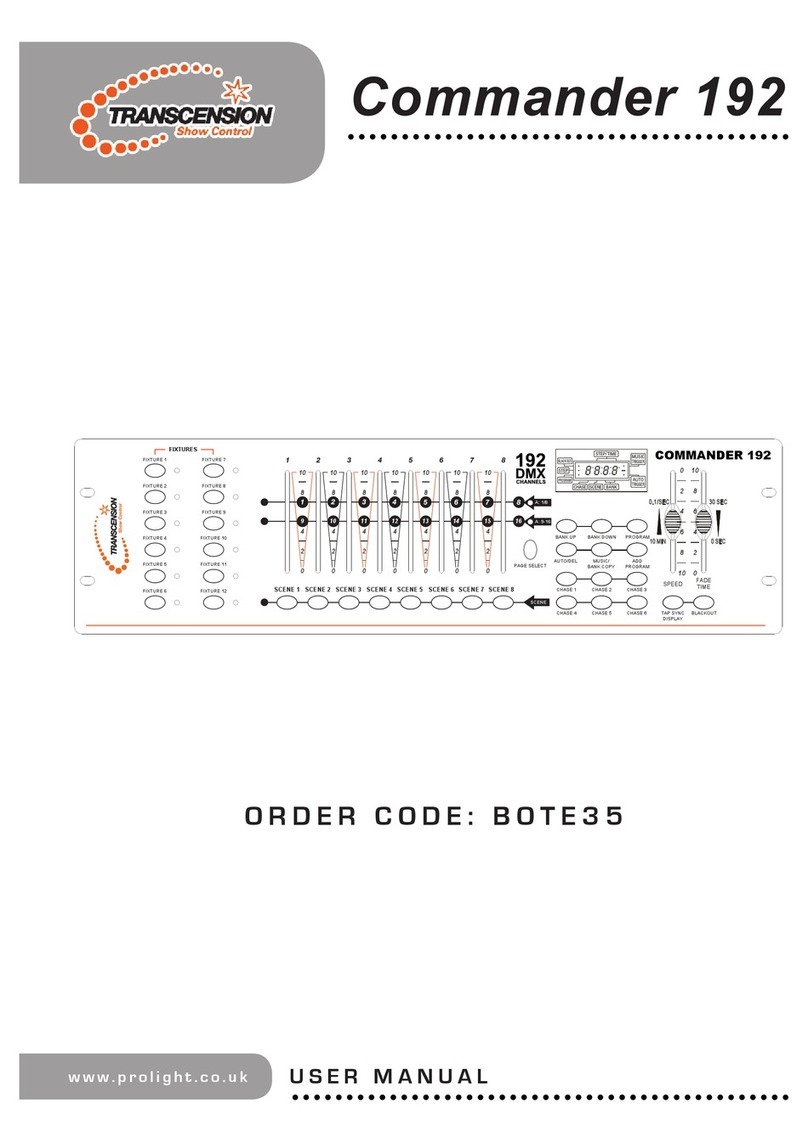
SFC SFCR-MH User manual

9/40 Layer Videowall Controller
Operation manual
SFCR-MH & SFCR-MD

Contents
1 Introduction .....................................................................................................................................................................................................1
Performance Characteristics Features.........................................................................................................................................................1
2 Hardware Installation.......................................................................................................................................................................................3
System requirement ....................................................................................................................................................................................3
Installation environment...............................................................................................................................................................................3
Installation environment requirements..................................................................................................................................................3
Recommend operating environment.....................................................................................................................................................3
Hardware installation steps ..................................................................................................................................................................3
Network connection..............................................................................................................................................................................3
Connection instruction.................................................................................................................................................................................4
3 PC Software Installation ..................................................................................................................................................................................5
Get the PC control software and IP setting tool ...........................................................................................................................................5
PC control software operation .....................................................................................................................................................................8
PC software main interface introduction.............................................................................................................................................10
3.1 Main function-screen group...................................................................................................................................................10
3.1.1 Screen group...............................................................................................................................................................10
3.1.2 Matrix mode ................................................................................................................................................................11
3.1.3 Video input source.......................................................................................................................................................12
3.1.4 Main function-Window control......................................................................................................................................14
3.1.5 Moving source.............................................................................................................................................................17
3.1.6 Adjust the source frame...............................................................................................................................................17
3.1.7 Modify the layer sequence...........................................................................................................................................18
3.1.8 Close the source .........................................................................................................................................................18
3.1.9 Image attribute ............................................................................................................................................................20
3.1.10 Group management...................................................................................................................................................23
3.1.11 Net video source........................................................................................................................................................25
3.2 Background manage .............................................................................................................................................................29
3.2.1 Background picture......................................................................................................................................................29
3.3 Subtitle manage ....................................................................................................................................................................30
3.3.1 New Caption................................................................................................................................................................30
3.3.2 Modify caption content.................................................................................................................................................30
3.3.3 Import existing subtitle files..........................................................................................................................................31
3.3.4 Delete the caption........................................................................................................................................................31
3.3.5 Adjust subtitle font, size and color ...............................................................................................................................31
3.3.6 Adjust the scroll direction of the subtitles.....................................................................................................................32
3.3.7 Adjust the scroll speed of the subtitles.........................................................................................................................32
3.4 Maintenance..........................................................................................................................................................................32
3.4.1 Maintenance-set..........................................................................................................................................................32
3.4.2 Maintenance-Signal name...........................................................................................................................................37
3.4.3 Maintenance-Screen switch.........................................................................................................................................38
3.4.4 Maintenance-Advanced setting....................................................................................................................................38
3.5 System..................................................................................................................................................................................38
3.5.1 System-connect...........................................................................................................................................................38
3.5.2 System-firmware license..............................................................................................................................................38
3.5.3 System-user................................................................................................................................................................39
4 Tablet App.....................................................................................................................................................................................................40
App installation and login...........................................................................................................................................................................40
App login............................................................................................................................................................................................40
App operation.....................................................................................................................................................................................40
5 IP address setting..........................................................................................................................................................................................42
IP setting tool ............................................................................................................................................................................................42
Tool operation....................................................................................................................................................................................42
6 Appendix.......................................................................................................................................................................................................43
Frequently asked questions.......................................................................................................................................................................43
Attentions..................................................................................................................................................................................................43


CAUTION
•Non-technician should not try to operate this controller before reading this manual carefully. (This manual are subject to change
without prior notice.)
•Cut the power supply off before operating the device to avoid damage caused by mal-operation.
•Interior of the controller are precision optical and electrical instruments. Heavy pressure, shock and other incorrect operations
should be prevented. Otherwise, may cause damage to product.
•Please do not use the product under circumstances where the limits exceed the maximum specified temperature, humidity or
power supply specifications.
•Contents in this manual may be different from the edition that you are using. Should any unsolved problem occur given that the
product is used according to this manual, please contact our technical support department or your product suppliers.
•This manual content will be updated unscheduled, our company reserves the right to do manual contents update without
further notice.
•The default username for this device is “admin”, and the password is blank. Default IP address is automatically appear after
your connection completed when you operate the software.

CKING LIST
Check if the packing contents match the packing list on receiving the products. The packing list is as below.
Part Quantity
DTMH/DTMD-04-4H4H 1
Mounting kit 1
Quick Start Guide 1
CD 1
Contact your local supplier if anything is missing in your package.

1
1 Introduction
Performance Characteristics Features
Equipment architecture:
1. FPGA + embedded architecture, the embedded system is stable, can support 7 * 24 hours of long-term operation, FPGA provides
users with stable image processing capabilities;
2. The equipment adopts a modular design, which can be flexibly matched with a variety of input and output boards, which can be
upgraded, expanded, and maintained;
Basic functions
3. Support HDMI, DVI, SDI, VGA, IP HD signal input, support HDMI UHD 4k/30 signal input, support DVI, HDMI HD digital signal
output;
4. Support single port to capture 1920x1080 ultra high definition signal; support single port to output 1920x1080 ultra high definition
signal;
5. Support 4K signal acquisition, single port acquisition of 3840x2160 ultra high-definition signal;
6. Support video frame rate of 60 frames;
7. Support the synchronous display of the monitor sub-screen, and you can set up to display the video window of the main video wall
on one or more display units;
8. The maximum 9 sources on one screen, and all window pictures are displayed in real time without dropping frames;
IP decode functions
9. Support H.264 IP camera decoding, support Onvif protocol or rtsp stream connection;
10. Support the integration of monitoring services and seamlessly connect with streaming media server, NVR and video storage server
equipment;
11. Support Onvif, RTSP protocol IP media stream interface and third-party surveillance video platform (such as: Dahua, Haikang)
video decoding on the wall;
Video wall functions
12. Achieve display functions of multiple signal sources on the wall, splicing, roaming, cross-screen, zoom-in, picture-in-picture, picture-
out-picture, screen overlay, etc.
13. Support all signals in the full screen range to open window roaming, superimposing, zooming, no window position, size, scale
restrictions;
14. Support single-screen multi-window segmentation;
15. Support ultra-high-definition special effect subtitle function, the font, color, size, scroll speed and direction of subtitles, background
color, background transparency can be flexibly selected;
16. Support ultra-high-resolution static pictures, pictures support multiple picture formats, support multi-window static layouts, quick and
easy replacement, and make the big screen pictures more colorful;
17. High-definition special effects subtitles on the output side, pixel-level display, overhead scrolling, full-screen scrolling, frame-level
synchronization;
18. Support WEB control, which can be used for computer / mobile phone / tablet to switch scenarios through WEB browser;
19. Support for saving 1000 pre-plan scenarios;
20. Scene switching, which can preset a variety of scenes in advance, easily achieve arbitrary switching of various scenes, support
scene rotation, and can customize the rotation interval;
21. Support multi-level user management, each user can set different operation permissions;
Other functions
22. Intelligent fan speed adjustment function, which can automatically adjust the fan speed according to equipment configuration and
temperature conditions in various areas to achieve green energy saving and environmental protection;

2
23. Support output port mapping technology. There is no need for one-to-one correspondence between the connection cables between
the device and the display unit. It is only necessary to ensure a valid connection. Port mapping settings are completed in the
control software, which greatly simplifies the installation process and shortens the installation time.
24. Support secondary development and provide third-party user control protocols and interfaces;
25. Independent intellectual property rights, adaptive de-interlacing, scaling, and OSD technology, the picture is smooth and clear;
26. Encryption function can control the time limit of product use.

3
2 Hardware Installation
System requirement
•Web browser: LAN Internet connect , via PC Ethernet ( network card or network cable) TCP/IP protocol
•Monitor and PC configuration: CPU: PⅢor latter, RAM: 2GB
•Operation system: Windows 7 or later
Installation environment
Installation environment requirements
Far away from humid or high-temperature environment; Choose proper place for ventilation; avoid installing on shaky place, and try to stay
away from heat device.
Recommend operating environment
Temperature:-10 ~ +60℃
Humidity: 5% - 95% Non-Condensing
Hardware installation steps
Please make sure LAN is working before installation . After checked all the system in good condition, keep your hands clean and dry,
following the steps below.
•Unpack the box to check the goods
•Take out all goods which needed for installation from the box
•Connect related cables according to actual need (Power line, network line, etc.)
•Connect the power supply
Please read the Note carefully, any question you should contrast us without hesitation.
Note:
•When open the box, please check all of parts carefully, confirm the parts in the box as same as packing list.
•Please read the user manual carefully before the installation.
•Make sure to turn off all the power when install the controller
•Please confirm the power transformer, avoid the device damage with unmatched power source
Network connection
•LAN connection
Use one network line to connect controller with concentrator or switchboard of the LAN, you can also use one network line to directly
connect controller
•Connect the power
After connect the power source, and press the power switch, the controller will start operation automatically.

4
Connection instruction
The appearance of the device is shown in the following figure;
1. The number "1" marked in the figure is the video output port of the processor, which is connected to the screen cable; the cable is freely
inserted into the OUT port on the processor, we will set the order later in the software;
2. The number "2" marked in the figure is the video input port of the processor. It connects to the local signal source (such as laptop, desktop,
Internet TV box, etc.); the software will automatically identify the signal source; if It is a decoding card, you need to insert a network cable into
the network port on the decoding card to access the router or switch.
3. The number "3" marked in the figure is the main control card of the processor. You need to insert a network cable into the network port on
the main control card to connect to the switch or router, or you can directly connect to the computer;
4. The number "4" marked in the figure is the power interface of the processor, which is connected to the 110V ~ 220V socket;
5. The number "5" marked in the figure is the grounding port of the processor.
Please make sure the processor's power supply and chassis are well grounded;

5
3 PC Software Installation
Get the PC control software and IP setting tool
There are 3 methods to control the LCD video wall controller, here I introduce the PC software control steps: double click the controller
PC software ("WTRemote_V1.0.X.X_setup.exe") then the below picture will pop out, click “Next”:
then the below picture will pop out, click “Next”. if you would like to select a different folder, click Browse, and then click”Next”:
Then select the start menu folder, and then click”Next”:

6
Then click to select create a desk icon, and then click”Next”:
And click”Install” to install the software on your computer:
Please wait the install the install processing:
After the installation completed, you can click “launch WTRemote” to operate the software, and then click “Finish”.

7
And the PC software icon and the IP setting tool(SearchNvsDemo.exe) will on the computer automatically, the icons
as following picture shows :
At the same time, you will get the PC software login interface,as following picture shows :

8
PC control software operation
You will get the IP address on the PC software login interface automatically after you connect successfully, the original user name of the
processor is: admin, the password is empty; if a different user and password are set, you need to log in according to the actual user name
and password, Follow the steps indicated by the numbers in the below picture:
After login, you will get a interface as below:
Click the menu "Maintenance”, then click “Screen Setting" to pop up the screen setting window (As shown below);

9
1. Screen resolution: set the resolution of the video output port;
2. Physical screen: set the number of rows and columns of the screen;
3. Logical screen: how many windows are divided by a single screen;
4. Port settings: pop-up screen port settings.
After click the “Port settings” menu, the screen will display the port numbers as follow:
And the software will pop up the following window, according to the card number and port number displayed on the screen, find the
corresponding card number and port number in the list on the left, hold down the right mouse button and drag to the corresponding box on the
right.
After all the settings are completed, click the Ok to complete the screen stitching settings.
00: Port0
02: Port 1
01: Port 1
02: Port 2
00: Port 2
00: Port 3
01: Port 0
02: Port 3
01: Port 3
02: Port 0
01: Port 2
00: Port 1

10
PC software main interface introduction
On the main interface the top horizontal bar, there are “Main function”, “Background manage", “Subtitle manage”, “Maintenance” and
“System” totally 5 parts. On the interface left part, it have “Video input source”, “Group management”, “Net video source” three parts.
After run the processor operating software and login, the signal source will list on the middle left under the “Video input source” part,
select a screen on the right virtual screen so that the screen has an orange border, then double-click a signal source with the left button of the
mouse, the signal source will display a window on the virtual screen, and the video will displaying on the screen as the same time, you can
drag, zoom in, zoom out, or close a window on the virtual screen, please refer to the below picture:
3.1 Main function-screen group
3.1.1 Screen group
There are “Window control”, “Screen group” and “View” three parts under the “Main function”. according to your video source and
display group, we set the screen group first:

11
When there are multiple sets of independent screens to be controlled by one controller, it is necessary to separate these groups of
screens in the control software.( If there is only one set of screens in the field, no screen grouping is required). Specific steps are as follows:
1)Select the No.1“screen group 2”(If have screen group 3,screen group 4, you can select corresponding)
2)Click No.2 “Enable screen group”
3)If you edit the group name as you need in the No.3
4)Other setting same as 2.3.2 and 2.3.3
After complete the group screen setting, on the Main function part to click “Group 2”, and also ,you can see the group 3 and group 4
virtual frame.
Select Group 2 and drag it to the window part, you can put the group 1 and group 2 together.
3.1.2 Matrix mode

12
Click "Matrix mode" in the main function tab to make its background blue. You can adjust the processor to matrix mode. In matrix
mode, all windows cannot be dragged to prevent misoperation; click again "Matrix mode" button to cancel the matrix mode. At this time, the
signal source window can be dragged.
3.1.3 Video input source
In the controller software, the video input source is divided into a local video input source and a network video input source, and the
local video input source refers to a one-to-one direct access signal source like DVI, VGA, coaxial cable, etc., network video input source
refers to the signal source connected to the controller through the network cable.
In the video input source part there are “tree”,“list”,“add dome”,“add matrix”four different content. “add demo”means
combine multiple different sources into one signal, usually used in conjunction with multi-screen graphics cards, using multiple input ports to
capture 4K, 8K and other ultra-high-definition signals, “add matrix”means the controller can linkage the front matrix switcher, it can display
all the input sources by matrix switcher, “tree”is used to display the all the input source ports and status, “list”is used to display the all
the effective input source.
3.1.3.1 Video input source-Tree
Click the “Tree”, and then click , it will expand the tree structure to see all the input card ports.

13
When a valid signal is connected to the processor, the system can automatically detect the input signal. Expand the tree structure
to see each input port. When the processor input port does not detect a signal input, the port indicator in the software is gray ,When the
processor input port detects a valid signal input, the corresponding port indicator in the software turns green (DVI、VGA、BNC、SDI
signal detection method is consistent), pls refer to below picture:
Input signal detected No Input signal detected
3.1.3.2 Video input source-List
Click the “List”, it will show all the input sources
3.1.3.3 Add combine
Add combine refers to the combination of multiple different signal sources into one signal, usually used in conjunction with multi-
screen graphics cards, using multiple input ports to collect 4K, 8K and other ultra high-definition signals. The specific operation method is as
follows
Add combine:
Click "Add combination" in the video input source tab, the combination input setting dialog box pops up
Enter the name of the combined signal in the Name field of the dialog box
Select the template for the combined input according to the arrangement of the signals
Select the signal source port number to be combined, set the “frame number, card number, port number”

14
After setting, you can see the icon of combined input in the video input list, double click the icon to open sources.
3.1.4 Main function-Window control
3.1.4.1 Open new source
A newly opened window refers to the input signal being displayed on the mosaic wall in the form of a window. In the control
software of the processor, there are various ways to open the window.
3.1.4.2 Single screen full screen
To turn a signal source on a screen,you can use the left mouse button to click the corresponding virtual screen on the right side of
the software interface to make the border of the virtual screen blue, then expand the video input source list on the left side of the software
interface, select the video source , and double-click the left mouse button, this signal source can be transferred to the corresponding display
unit to get a full screen display (the local video source in the "tree" and "list" can be directly displayed , the network video source must be in
the "list" or network Double-click the signal source icon in the video source tab to open the window. At this time, the orange frame on the
virtual screen will move to the next screen. When you continue to double-click the signal source, a new source will open on the next display
unit.
3.1.4.3 Drag and drop to open source
Use the left mouse button to click and select a signal source in the video input source list. Press the left mouse button on the right
main view, drag the mouse, draw a dashed box, and then release the left mouse button. The main view will be fired. The window of this signal
source is the same size as the dashed box.
Drag the dotted box

15
Source on the screen
3.1.4.4 Single screen split
Single-screen split-window refers to opening multiple different signal source windows in one screen. There are two methods for
single-screen split-window:
Method 1:in the part of “Window control”, select the number of rows and columns that need to be split for a single screen, split the
single screen into multiple logical screens, and then select the logical screen to open the sources.
Method 2:
In the main view, select the screen that needs to use the single-screen split quick template, right-click the right mouse button as
shown below
This manual suits for next models
1
Table of contents
