CSC-3000 Series Pneumatic VAV Reset Volume Controllers 4 Applications Guide
Adjustments and Calibration
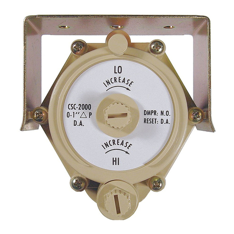
Damper Action
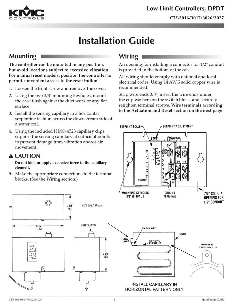
The damper action is factory-set at Normally Open
(N.O.). To change to Normally Closed (N.C.), per-
form the following steps:
1. Loosen the damper selection screw.
2. Turn the selection dial clockwise until the “NC”
arrow aligns with the “DAMPER” arrow.
NOTE: Accuracy in the alignment of the arrows is
very important. Make this adjustment as
exact as possible.
3. Tighten the selection screw. Be sure the
screw is tight (2 to 4 in-lbs. of torque), but if
overtightened, the plastic will strip out.
DIRECT RESET Minimum and Maximum
Determining the Type of Reset
The following table shows when Direct Reset or
Reverse Reset is required. Determine the reset type
based on the temperature of the primary air entering
the VAV box and whether the thermostat in the space
is direct or reverse acting.
3 psig 8 psig 13 psig
Thermostat Pressure
Max. Airflow
Min. Airflow
Reset Start Point (8 psig)
Reset Span (5 psig)
Adjusting Minimums and Maximums
When adjusting the minimum and maximum airow
seings, the output responds slowly to changes in
the setpoint. Wait for the ow rate to stabilize aer
making an adjustment (usually 20 to 30 seconds) be-
fore making further adjustments. Also, if the damper
position is all the way closed or open when starting
this step, turn the adjustment one full turn, and then
wait 20 to 30 seconds for a change in the ow read-
ing of the Magnehelic gauge. If no change occurs
aer this time, repeat until the ow rate changes.
NOTE: The direct reset illustration above assumes
no relays are connected between the
thermostat and “T” port.
For Direct Reset (DA thermostat for cooling or RA
thermostat for heating), perform the following steps:
1. Adjust the thermostat to a seing that will cause
the output pressure to be as high as possible (15
psi or more). This can be done in the following
manner:
a. For Direct Acting thermostats, lower the
seing to the lowest possible seing.
b. For Reverse Acting thermostats, raise the
seing to the highest possible seing.
2. On the CSC-3000, disconnect the “T” port.
Temporarily plug the tubing. (Do NOT plug the
port.)
3. Adjust the LO STAT ∆P (center dial) one
adjustment (1/4 to 1/2 knob rotation) at a time
until the desired Minimum airow is read at the
Magnehilic gauge and is stable.
NOTE: If the LO STAT ∆P Limit must be set at
“0” (zero minimum), do not turn the LO
STAT ∆P knob fully clockwise. The knob
will adjust one and one-half turns aer a
zero minimum is reached. Turning the LO
STAT ∆P knob fully clockwise will result
in a negative reset condition. This means
that when the controller begins to reset at
the reset start point it must rst overcome
the negative adjustment and will not begin
to reset from “0” until a higher thermostat
reset pressure is reached. This negative
reset will also reduce the eective range
of the controller by reducing the low end
reset; narrowing the reset span. If a zero
minimum is required, adjust the LO STAT
∆P knob until the controller just begins
to crack the damper open, then back-o
one-quarter turn and verify zero airow.
(This is typically 2-1/2 knob rotations
counterclockwise from the fully clockwise
position.)
4. Reconnect the thermostat tubing to the “T” port.
This will put 15 PSI or more on the “T” port.
5. Adjust the HI STAT ∆P (dial on right) one
adjustment (1/4 to 1/2 knob rotation) at a time
until the desired Maximum airow is read at the
Magnehilic gauge and is stable.
6. Repeat Steps 2 through 5 to verify the seings to
be correct and ne tune if necessary.
Primary Air Thermostat Reset Type
Cooling DA Direct Reset
RA Reverse Reset
Heating DA Reverse Reset
RA Direct Reset
