SFS Soter User manual
Soter fall protection and wire system
Installation
manual

2SFS / Installation manual Soter
Typical Fall Arrest System layout
Fall Arrest
When a work restraint system cannot be feasibly offered, then a
fall arrest system can then be considered.
Fall arrest systems are designed to ‘limit the consequences of a
fall should it occur’.
The Soter HLL system will arrest a users’ fall, only if the required
fall clearance has been allowed.
Fall clearances must be factored in when a fall arrest system is
designed, considering the following factors;
nBuilding height
nFree fall distance from roof edges
– To the ground
– Lower level roofs/adjacent buildings
nFree fall distance through fragile roof areas/roof lights/canopies
etc.
Although fall arrest systems are often employed to give a user full
roof access, they come with major disadvantages, such as;
nThey do not stop a fall from height occurring as the user has
flexibility of PPE lengths.
nThey can only be used on buildings with the required free fall
clearance from all fall hazards including through roof lights.
nA full rescue plan must be in place to return the user
to safety, often this is overlooked.
nThe users must be trained so they can use extra PPE equipment
safely including extended rope and grab devices and anti-
pendulum/swing posts.
*Soter systems should not be designed to arrest on standing seam
roof sheets due to the weakness of the connection between clip
and sheet which will not give required arrest figures.
Key:
A – Soter HL Start/End post with female M10/Universal
B – Soter R Intermediate post with intermediate bracket
C – Soter HL Corner with corner kit/solid corner
D – Soter anti-pendullum/swing post
Work Restraint
Work restraint systems are the safest method of HLL system
design. Keeping a user in restraint removes the possibility of fall
occurring. The users path, and what they have access to can be
dictated/controlled.
Keeping a user in restraint is dictated by the relationship of two
key distances;
nLanyard length (A)
nPosition of the system and distance away from fall hazard (B),
*see figure adjacent and on page 6
If the achievable distance between position of line and fall hazard
varies on the system route, the lesser distance and therefore
lanyard length should be preferred before any variable lanyard
lengths/multiple lanyards are proposed.
The general spacing from system to roof edge/fall hazard is 2.30m
based on a typical lanyard length of 1.85m.
Fall Hazards can be roof edges, roof lights or other fragile roof
areas such as windows/glass.
Main advantages of Work Restraint systems;
nNo possibility of a fall
nNo need for any rescue plan
nAdjacent buildings/lower level roofs and fall clearances do not
need to be factored
nMinimal system user training required
Typical Work Restraint System layout
Key:
A – Soter HL Start/End post with female M10/Universal
B – Soter R Intermediate post with intermediate bracket
C – Soter HL with intermediate bracket
D – Soter HL T-Off with 2 hole plate and intermediate bracket
E – Soter HL Corner with corner kit/solid corner
D
AB
A
C
DD
D
ABE
B
B
B
B B B
B
E
D C
A
A
Installation manual

SFS / Installation manual Soter 3
Free-Fall Clearances
Free fall clearances are often overlooked when a fall
arrest system is designed.
It’s imperative they are calculated using a calculation
programme by the manufacturer, to prove that if a fall
was to occur, the distances required for the system to
effectively arrest the users fall can be assured.
System deflection and wire elongation is calculated
using the Soter calculation package, taking into account
system length, post spacing and maximum span length,
and the number of users.
This calculation package is available to all approved
Soter installers. SFS can also make design calculations
in house on request.
Once system deflection and wire elongation is known,
this distance can be added to the following
measurements to calculate a free fall clearance
distance:
nUsers Height (A)
nLanyard Length (B)
nDeployed shock absorber length (C)
nSafety Factor (D)
= Minimum free fall clearance required (Z)
Maximum System Lengths
Soter systems can support straight system lengths
up to a maximum of 250m, however this figure
reduces once you add a corner, and further for every
subsequent corner added. This is mainly down to the
static loading that a corner post is subjected to under
system tensioning. The more corners, the more load
each corner post must support in two directions which
can cause post lean.
Please refer to guidelines adjacent, however this
should be assessed at the installers discretion on site.
For further information on the system please see the complete Soter installation manual on
www.sfsintec.biz/se
Number of Corners Max. System Length
Straight run 250m
1 175m
2- 4 150m
5+ 125m
*It is advised that systems of long lengths, or those that have multiple
turns, have a tensioning termination at both ends of the system, so
that the tension can be pulled into the line from both ends.
Introduction
The Soter guide
This guide has been compiled to ensure the correct
installation of Soter HLL systems is adhered to at all times.
The installer should have previous HLL system installation
knowledge, design understanding, or, have taken part in Soter
HLL training.
It is important that the installer fully understands this guide
before commencement of Soter installation on site.
Soter HLL Systems are designed to act as a fall prevention
method, or that of a means of minimising the consequences
of a fall should it occur.
Only trained personnel should be involved in the design,
correct installation, and recertification of HLL systems. Failure
to follow this guide could put people’s lives at risk.
It is imperative that the correct components are used for the
specific application, and any doubts should be resolved by
seeking guidance from SFS Fall Protection.

4SFS / Installation manual Soter
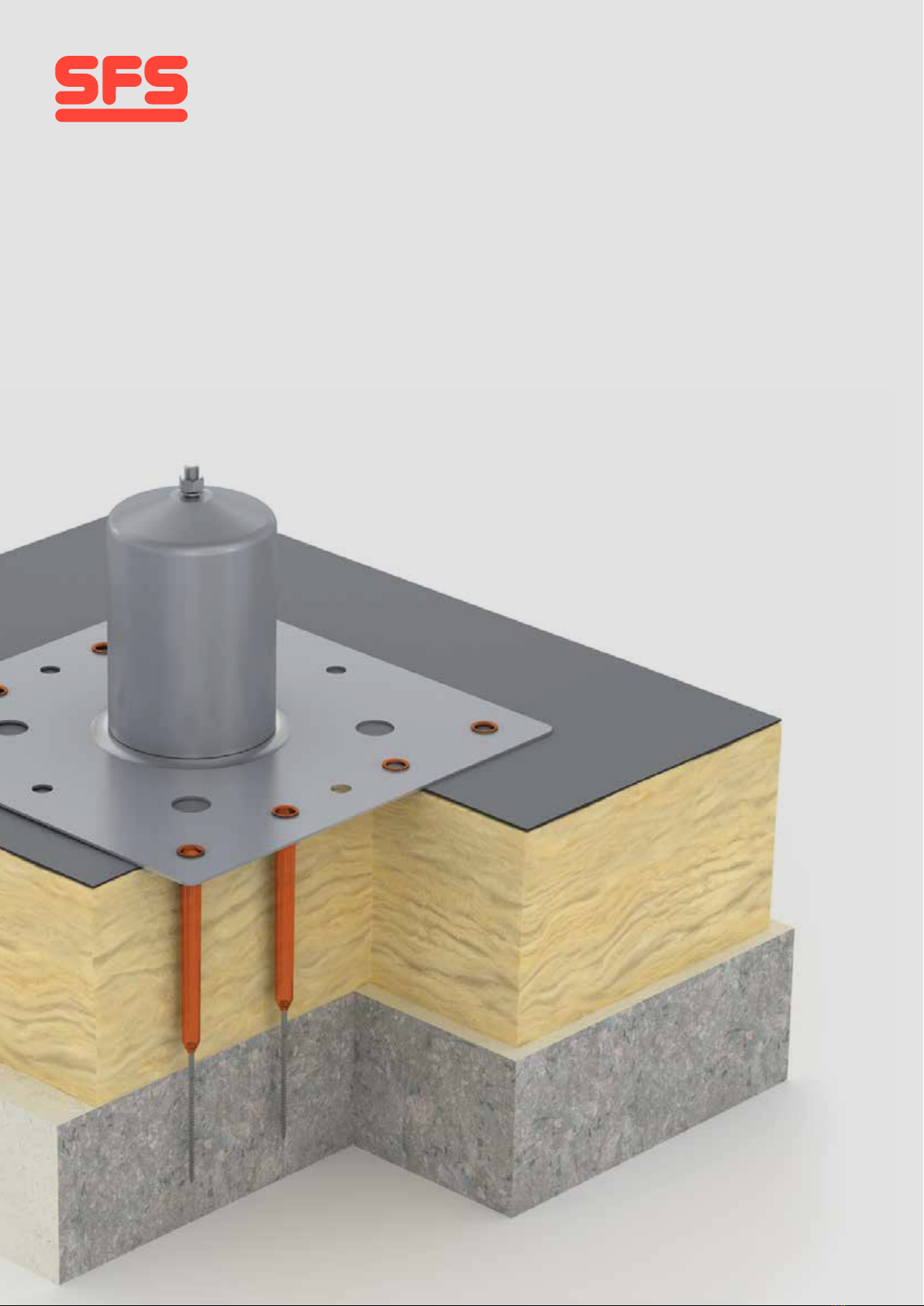
Use 8 no. PA Sleeve’s and TI Screws for concrete / Using 8 no. PA sleeves and BS screws
for 18mm Ply /OSB Board or 0.7mm Metal deck or tongue and groove deck
➊Ascertain location of base plate
picking up the crown or trough
of the deck based on the fixing
length supplied.
➍With all 8 fixings installed turn
S2 can onto female boss in base
plate by hand firstly then to the
desired tightness by hand or with
the help of a tool.
➎Anchor installation is complete
and is ready for Soter
components to be secured.
➋Insert the sleeves ➌Take drill fitted with extended drive
bar and T25 Torx bit and fix all 8 no.
fasteners through tubes, insulation
build up and deck, securing firmly.
DO NOT OVERDRIVE.
Step 1
Anchor installation

SFS / Installation manual Soter 5
➋Mark on the termination where
the wire ends. This shows where
the hollow part of the termination
ends, and where the first crimp
will be located.
➎Mark on the termination where
the wire ends. This shows where
the hollow part of the termination
ends, and where the first crimp
will be located. This needs to
be done on all terminations-
tensioners and toggle fork ends.
➌Repeat step 2 on all terminations-
tensioners and toggle fork ends.
Re-insert the wire fully ensuring
the wire is fully engaged in the
termination up to the point marked.
➏Re-insert the wire fully ensuring
the wire is fully engaged in the
termination up to the point marked.
➍Take the crimping tool and set the
barrel to ‘close’. Position the central
section of the die so that the first
crimp is made next to the line
marked on the termination itself.
➊Pull the wire though the whole system and through all posts. Before any accurate measurement can be made, the
wire must first be loosely pulled from the start of the system, through every component fitted to posts to the end point.
Step 2
Wire measure & wire crimp
➐As you reach the start of the line,
you will have manually pulled the
wire enough so that it doesn’t
touch the roof surface, and has
reasonable tension in it.

6SFS / Installation manual Soter
Step 3
Cutting & tensioning
➎By holding the crimped barrel and
line in one hand the turnbuckle/
central barrel of the tensioner can
be turned tensioning the line with
the other hand.
➏Once the required amount of tension has been achieved the red tension
indicating disc will loosen and can be turned. Although this indicates the
required amount of tension (0.8kN) has been achieved, it is the installers
responsibility to check each straight-line span has enough tension in it and
the tension is evenly distributed throughout the system. The nuts on the
tensioner can now be tightened against the turnbuckle, locking it in place.
➍Once the end termination has
been fully crimped it can be
properly secured onto the end
component and the nut and bolt
fully tightened.
➊To gain the most accurate mea-surement it is advised to swage/crimp the end termination and fix to the end post
component.
➋Work your way back to the end
of the system making sure the
wire has the right tension and cut
the wire.
➌Repeat the wi recrimp procedeur
2-6 at the start of the system.
SFS / Installation manual Soter 7
Final tightening &
system tagging
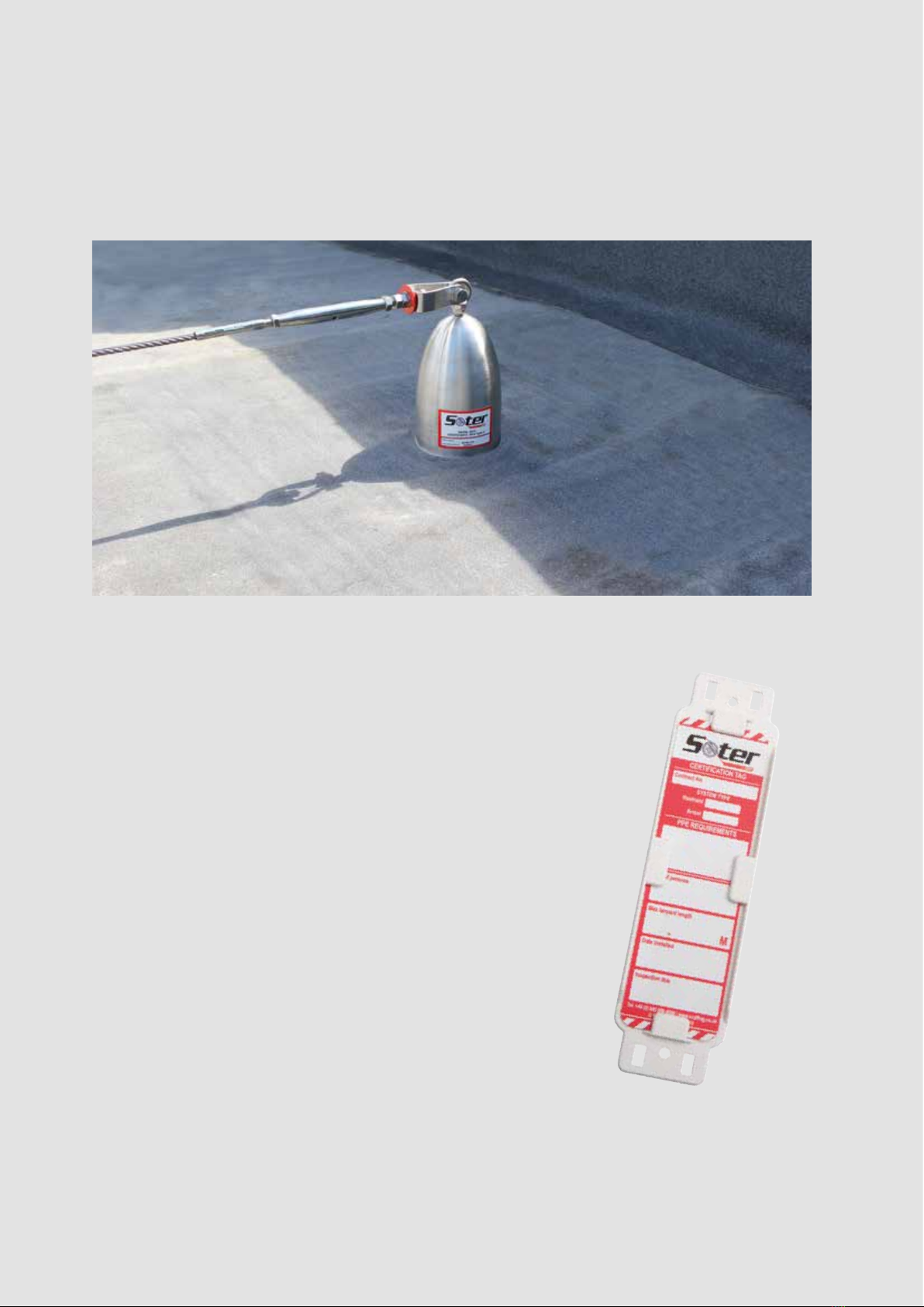
It is important that all installed systems are fitted with a certification tag at
the point of access, similar to the tag shown opposite. Conforming to BS EN
365:2004
The certification tag should include the following information to support the
more detailed O&M Manual:
nContract number/name so that the system can be identified
nSystem type- Restraint/Arrest
nPPE Requirements for the user to use the system safely & correctly
nNo. of persons the system is designed for
nMaximum lanyard length- imperative in work restraint systems
nInstallation date
nRecertification/inspection due by date
If the recertification date has lapsed, the system should not be used until a
recognised/approved Soter installer has recertified the system as fit for use.
Systems are required under EN795 to be recertified annually.
➊Finally, all system components should be fully tightened down to each post, and a final walk of the system
should be performed ensuring everything is secure and nothing has been missed.

55
04/2015
11
WFR-T-T20-4 x L
Material: Carbon steel
Coating: zinc electroplating
Diameter: 4 mm
Drive: TORX
® T20
WFR-T-T20-4,5 x L
Material: Carbon steel
Coating: zinc electroplating
Diameter: 4,5 mm
Drive: TORX
® T20
WFR-T-T25-5 x L
Material: Carbon steel
Coating: zinc electroplating
Diameter: 5 mm
Drive: TORX
® T25
WFR-T-T30-6 x L
Material: Carbon steel
Coating: zinc electroplating
Diameter: 6 mm
Drive: TORX
® T30
d
l
WF A comprehensive range for timber to timber
Fastening System and steel to timber connections
Fastener Range
Type Material
T =
carbon
steel
Drive Diameter
d in mm
Length
l in mm
WFR - T - T25 - 5 x 20
WFR - T - T25 - 5 x 25
WFR - T - T25 - 5 x 30
WFR - T - T25 - 5 x 35
WFR - T - T25 - 5 x 40
WFR - T - T25 - 5 x 50
WFR - T - T25 - 5 x 60
WFR - T - T25 - 5 x 70
WFR - T - T25 - 5 x 80
WFR - T - T25 - 5 x 90
WFR - T - T25 - 5 x 100
WFR - T - T25 - 5 x 110
WFR - T - T25 - 5 x 120
WFR - T - T20 - 4 x 20
WFR - T - T20 - 4 x 25
WFR - T - T20 - 4 x 30
WFR - T - T20 - 4 x 35
WFR - T - T20 - 4 x 40
WFR - T - T20 - 4 x 45
WFR - T - T20 - 4 x 50
WFR - T - T20 - 4 x 60
WFR - T - T20 - 4 x 70
WFR - T - T20 - 4,5 x 20
WFR - T - T20 - 4,5 x 25
WFR - T - T20 - 4,5 x 30
WFR - T - T20 - 4,5 x 35
WFR - T - T20 - 4,5 x 40
WFR - T - T20 - 4,5 x 45
WFR - T - T20 - 4,5 x 50
WFR - T - T20 - 4,5 x 60
WFR - T - T20 - 4,5 x 70
WFR - T - T20 - 4,5 x 80
Fastener Range
Type Material
T =
carbon
steel
Drive Diameter
d in mm
Length
l in mm
Fastener Range
Type Material
T =
carbon
steel
Drive Diameter
d in mm
Length
l in mm
WFR - T - T30 - 6 x 50
WFR - T - T30 - 6 x 60
WFR - T - T30 - 6 x 70
WFR - T - T30 - 6 x 80
WFR - T - T30 - 6 x 90
WFR - T - T30 - 6 x 100
WFR - T - T30 - 6 x 110
WFR - T - T30 - 6 x 120
WFR - T - T30 - 6 x 130
WFR - T - T30 - 6 x 140
WFR - T - T30 - 6 x 150
WFR - T - T30 - 6 x 160
WFR - T - T30 - 6 x 180
WFR - T - T30 - 6 x 200
WFR - T - T30 - 6 x 220
WFR - T - T30 - 6 x 240
WFR - T - T30 - 6 x 260
WFR - T - T30 - 6 x 280
WFR - T - T30 - 6 x 300
Fastener Range
Type Material
T =
carbon
steel
Drive Diameter
d in mm
Length
l in mm
Turn ideas into reality.
SFS intec AG / Division Construction / CH-9435 Heerbrugg / construction@sfsintec.biz / www.sfsintec.biz
© SFS intec, i-TW 905984, 05-2014
WF_01_EC5_en_CH_Hgg_1.02_general
Technical changes reserved. Created in Switzerland
All calculations have to be checked and approved by the responsible
planner ahead of execution. The user is responsible to assure compliance
with all applicable laws and regulations.
11.
WF
Timber toTimber and Steel toTimber Connections
Technical documentation and data sheets Technical documentation and data sheets
© SFS February 2018.
Subject to technical modifications
and price changes. Printed in Sweden.
SFS
Olivehällsvägen 10
SE-645 42 Strängnäs
T +46 (0)-152 71 50 00
www.sfsintec.biz/se
Table of contents
Other SFS Safety Equipment manuals


Popular Safety Equipment manuals by other brands

Blue Star
Blue Star 6801109 instruction manual

FormFit
FormFit HDW 5R 02 quick start guide

Wenglor
Wenglor OSEI Z0103 Series operating instructions

Tecomec
Tecomec 5120903 owner's manual

Chloride
Chloride F100 Installation and operating instructions

Falltech
Falltech DuraTech Max Web Single User instruction manual


