RITE-HITE Dok-Lok STR-4000 User manual

This Manual Covers Serial No. 05GD150001W And Up
PRINTED IN U.S.A. RITE-HITE PRINT SHOP PUBLICATION NO. 1200
Copyright 2004, 2005 NOVEMBER 2005
STR-4000 Dok-Lok®
Vehicle Restraint
Installation Manual
MADE IN U.S.A.

2Pub. No. 1200 — November 2005
RITE-HITE STR-4000 DOK-LOK Installation Manual
INTRODUCTION . . . . . . . . . . . . . . . . . . . . . . . . . . . . . . . . . . . . . . . . . . . . . . . . . . . . . . . . . . . . . . . . . . . . . . . . . . . 2
SAFETY WARNINGS . . . . . . . . . . . . . . . . . . . . . . . . . . . . . . . . . . . . . . . . . . . . . . . . . . . . . . . . . . . . . . . . . . . . . . . . 3
INSTALLATION. . . . . . . . . . . . . . . . . . . . . . . . . . . . . . . . . . . . . . . . . . . . . . . . . . . . . . . . . . . . . . . . . . . . . . . . . . . . . . . 5
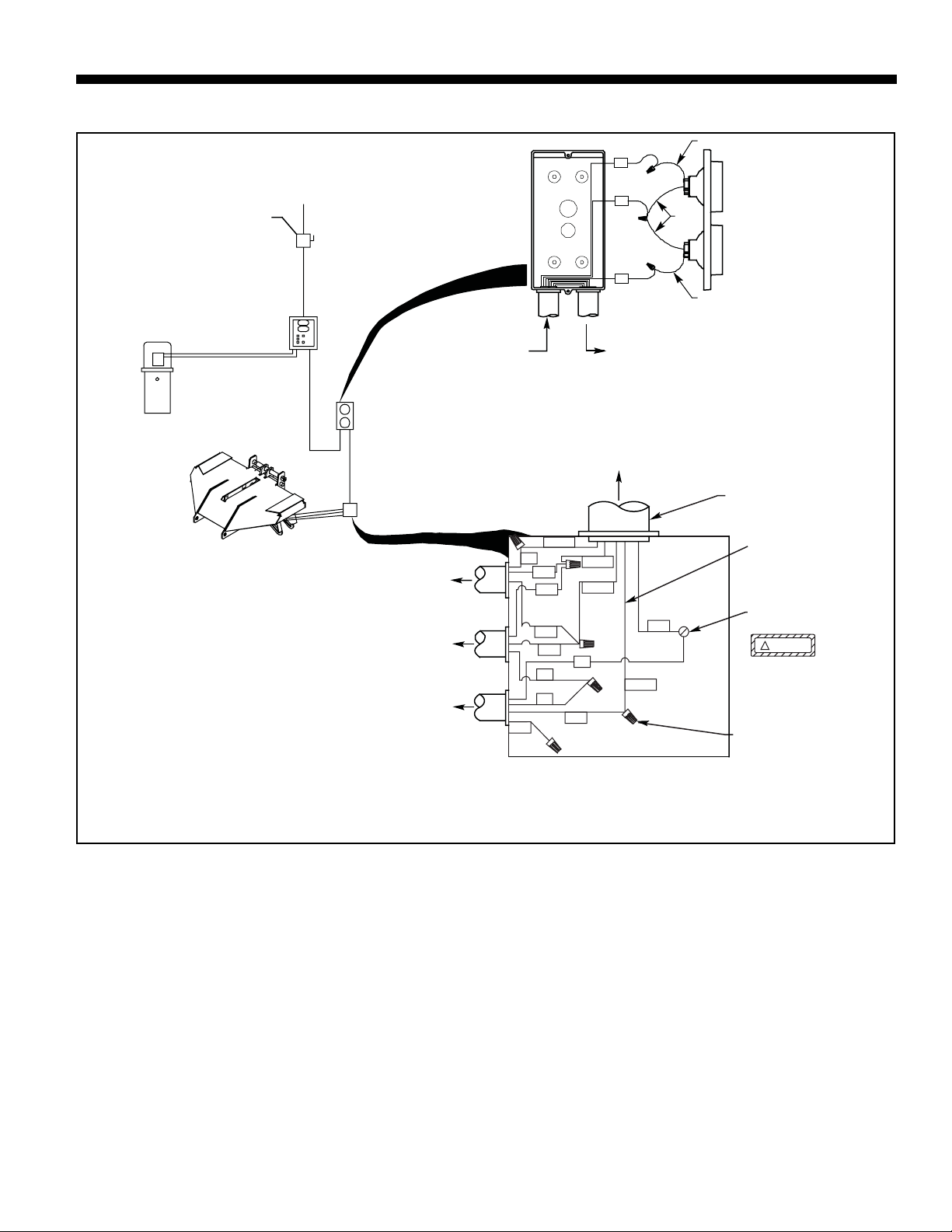
WIRING DIAGRAM - STAND ALONE POWER UNIT . . . . . . . . . . . . . . . . . . . . . . . . . . . . . . . . . . . . . . . . . . . . . . . . 9
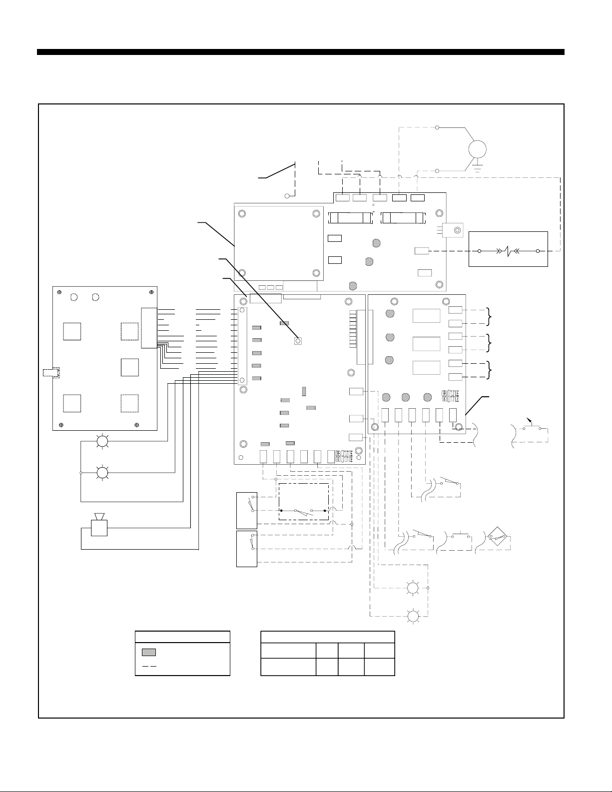
ELECTRICAL SCHEMATIC - STAND ALONE POWER UNIT. . . . . . . . . . . . . . . . . . . . . . . . . . . . . . . . . . . . . . . . . . 10
WIRING DIAGRAM - COMBINATION POWER UNIT . . . . . . . . . . . . . . . . . . . . . . . . . . . . . . . . . . . . . . . . . . . . . . . 11
ELECTRICAL SCHEMATIC - COMBINATION POWER UNIT. . . . . . . . . . . . . . . . . . . . . . . . . . . . . . . . . . . . . . . . . . 12
HYDRAULIC INSTALLATION. . . . . . . . . . . . . . . . . . . . . . . . . . . . . . . . . . . . . . . . . . . . . . . . . . . . . . . . . . . . . . . . . . . . 13
HYDRAULIC SCHEMATIC - STAND ALONE POWER UNIT . . . . . . . . . . . . . . . . . . . . . . . . . . . . . . . . . . . . . . . . . . . 14
HYDRAULIC SCHEMATIC - COMBINATION POWER UNIT . . . . . . . . . . . . . . . . . . . . . . . . . . . . . . . . . . . . . . . . . . . 15
VALVE BLOCK ASSEMBLY . . . . . . . . . . . . . . . . . . . . . . . . . . . . . . . . . . . . . . . . . . . . . . . . . . . . . . . . . . . . . . . . . . . . . 16
SPECIAL APPLICATION INSTALLATION ITEMS . . . . . . . . . . . . . . . . . . . . . . . . . . . . . . . . . . . . . . . . . . . . . . . . . . . . 17
WARRANTY . . . . . . . . . . . . . . . . . . . . . . . . . . . . . . . . . . . . . . . . . . . . . . . . . . . . . . . . . . . . . . . . . . . . . . . BACK COVER
TABLE OF CONTENTS
INTRODUCTION
Read and understand this manual before attempting to install or operate any DOK-LOK vehicle restraint. For best
results, have this product serviced by your authorized RITE-HITE representative. The STR-4000 DOK-LOK vehicle
restraint by RITE-HITE is intended to provide a safer workplace for workers in shipping and receiving dock areas. The
STR-4000 DOK-LOK vehicle restraint is an hydraulic restraint device that, when properly installed and operated,
retains a secure connection between the truck and dock. Signal lights and signs provide instructions to the truck driver
and DOK-LOK vehicle restraint operator that a safe condition exists. The DOK-LOK vehicle restraint is operated by
pressing push buttons on an inside control panel.
NOTICE TO USER
Your local RITE-HITE®representative provides a Planned Maintenance Program (P.M.P.) which can be fitted to your
specific operation. Call your local representative or the RITE-HITE®Corporation at 414-355-2600.
The RITE-HITE®products in this manual are covered by one or more of the following U.S. patents: 4,744,121;
4,819,770; 4,843,373; 4,865,507; 4,920,598; 4,995,130; 5,040,258; 5,111,546; 5,212,846; 5,271,183; 5,299,386;
5,311,628; 5,323,503; 5,375,965; 5,440,772; 5,442,825; 5,453,735; 5,531,557; 5,546,623; 5,553,987; 5,582,498;
5,664,930; 5,702,223; 5,762,459 (RE: 37,570); 5,882,167; 5,964,572; 6,010,297; 6,052,268; 6,065,172; 6.070,283;
6,074,157; 6,085,375; 6,092,970; 6,106,212; 6,116,839; 6,190,109; 6,220,809; 6,627,016; 6,238,163; 6,311,352;
6,322,310; 6,360,394; 6,368,043; 6,431,819; 6,488.464; 6,497,067; 6,499,169; 6,505,713; 6,524,053; 6,634,049;
6,654,976; 6,676,360; 6,726,432; 6,773,221 and pending U.S and foreign patent applications. RITE-HITE®, LEVEL-
RITE®, THINMANTM, SAFE-T-LIP®, HYDRACHEK®, WHEEL-LOKTM, DOK-LOK®, DUAL-DOK®, SAFE-T-STRUTTM, DOK-
COMMANDER®, JUMBOTM, HYDRA-RITETM and SAFE-T-GATE®are trademarks of RITE-HITE®Corporation.

Pub. No. 1200 — November 2005 3
RITE-HITE STR-4000 DOK-LOK Installation Manual
SAFETY WARNINGS
LOCKOUT/TAGOUT PROCEDURES
The Occupational Safety and Health Administration requires that, in addition to posting safety warnings and
barricading the work area, the power supply has been locked in the OFF position or disconnected. It is mandatory
that an approved lockout device is utilized. An example of a lockout device is illustrated. The proper lockout
procedure requires that the person responsible for the repairs is the only person who has the ability to remove the
lockout device.
In addition to the lockout device, it is also a requirement to tag the power control in a manner that will clearly note
that repairs are under way and state who is responsible for the lockout condition. Tagout devices have to be
constructed and printed so that exposure to weather conditions or wet and damp locations will not cause the tag to
deteriorate or become unreadable.
RITE-HITE®Corporation does not recommend any particular lockout device, but recommends the utilization of an
OSHA approved device (refer to OSHA regulation 1910.147). RITE-HITE®Corporation also recommends the review
and implementation of an entire safety program for the Control of Hazardous Energy (Lockout/Tagout). These
regulations are available through OSHA publication 3120.
This is the highest level statement. Failure to
follow the listed instructions will most likely
result in severe injury or death.
IMPORTANT is used to draw attention
to a procedure that needs to be followed to
prevent machine or property damage.
When working with electrical or electronic
controls, make sure that the power source has
been locked out and tagged according to OSHA
regulations and approved local electrical codes.
This is a statement of serious hazard. Failure to
follow the listed instructions could place the
individual at risk of serious injury or death.
The statements used with this level of
warning deal with a safe operating
procedure. If the procedure is ignored, the
possibility of personal injury may exist.
Lockout/Tagout

4Pub. No. 1200 — November 2005
RITE-HITE STR-4000 DOK-LOK Installation Manual
SAFETY DEVICES
• Post warnings and barricades at dock level
and at drive level to indicate that work is
being done around and under the leveler
platform.
• Lockout/Tagout power to the leveler and post
warnings when work is being performed on
the leveler.
Never be under the dock leveler platform or lip
without:
• Install the Safe-T-Struttm or other manufacturer
approved supporting device. See figure 2.
• If you are unable to install the Maintenance
Support properly, contact your authorized
RITE-HITE® Service Representative or RITE-
HITE® Customer Service at 1-414-355-2600.
Figure 2 - Install Safe-T-StrutTM Support
Power Moving Components
Serious Injury Could Occur
HANDS
OFF
NO
STEP

A DOK-LOK vehicle restraint may be installed on docks
with or without levelers. Consult RITE-HITE for proper
application.
Follow the six (6) step installation procedure below:
1. Inspect DOK-LOK materials.
2. Anchor or Weld track.
3. Position DOK-LOK assembly into track.
4. Electrical component and sign installation.
5. Hydraulic installation.
6. Test operation.
INSPECT DOK-LOK MATERIALS
Open and inspect all materials. Immediately report any
damage or material shortage. Study component
assemblies and determine their proper locations.
Install DOK-LOK vehicle restraint onto dock face at 27
inches off of the approach, unless otherwise noted in the
“RITE-HITE Installation/Application Guidelines”, at the
specified location by welding to an embedded steel plate
or by using the concrete anchors provided in conjunction
with welding to pit steel and a leveler frame. The track
will need to be trimmed if the mounting height is less than
26 inches. A maximum of 1 inch is allowed between the
bottom of the track and the approach.
For site specific installation refer to RITE-HITE
Installation/Application information provided with DOK-
LOK vehicle restraint. If the recommended mounting
height cannot be achieved call your RITE-HITE
Representative or RITE-HITE Customer Service at (800)
456-0600.
NOTES:
a. Some levelers may be slightly recessed or protruding
within pit. A shim must be inserted between the roller
track plate and the leveler front subframe and then
must be welded in place. See page 17.
b. If the dock conditions DO NOT allow lights and signs
to be mounted in full view of the forklift and/or truck
trailed drivers, consult the factory.
c. If the DOK-LOK is installed with a hydraulic leveler,
verify that the leveler’s recycle function has not been
adversely affected.
d. Track MUST be centered. Offset track installations
ARE NOT allowed. If there is existing anchor hole
interference call your RITE-HITE Representative or
RITE-HITE Customer Service at (800) 456-0600.
e. Approach must be concrete or there must be a
concrete pad where the base plate is installed.
STR-4000 DOK-LOK®INSTALLATION
When lifting carriage use a proper lifting device
(ex. crane, jack). Lifting by hand may cause back
injury.
When working with electrical or electronic
controls, make sure that the power source has
been locked out and tagged according to OSHA
regulations and approved local electrical codes.
Whether there is a leveler or not, a 4" thick
bumper is required. DO NOT install a DOK-LOK
vehicle restraint on docks without 4" thick
bumpers. For thicker bumpers consult factory.
Pub. No. 1200 — November 2005 5
RITE-HITE STR-4000 DOK-LOK Installation Manual
Never be under the dock leveler platform or lip
without:
• Installing the Safe-T-StrutTM or other
manufacturer approved supporting device.
• Turning off power to the control box.
• Locking out and tagging out the main
power source, as shown under Safety
Warnings on page 3.

6Pub. No. 1200 — November 2005
RITE-HITE STR-4000 DOK-LOK Installation Manual
INSTALLATION CONT.
ANCHOR TRACK
1. Put DOK-LOK vehicle restraint track in place.
2. Drill holes of 5/8" diameter and minimum of 4-1/2"
deep. Clean out holes.
3. Insert anchor and drive flush with roller track plate,
making certain that the threaded wedge is put in first.
Do not disassemble anchor prior to installation.
4. Torque all anchors to 100 ft-lbs.
5. Remove track cover plate and weld top of track to
leveler front frame angle and/or pit steel. WELD TRACK
If the installation being worked on is a “reinstallation” the
following electrical connections must be disconnected
prior to welding. Make sure to LOCKOUT/TAGOUT the
power at the fused disconnect, then remove sensing
switch connections from control box. Once all welding
procedures have been completed, reconnect all wires.
1. Put DOK-LOK vehicle restraint track in place.
2. Plug weld all holes that are in contact with embedded
mounting plate. All holes must be either plug welded
or anchored.
3. Remove track cover plate and weld top of track to
leveler front frame angle and/or pit steel.
NOTE 1: Figure 2 – Shims must be the full length of the
roller track mounting plate and base plate.
Minimum electrode must be 1/8" 7018 or better.
NOTE 2: Figure 2 – Never install DOK-LOK vehicle
restraint directly onto concrete block or brick
dock face.
NOTE 3: Figure 2 – When welding DOK-LOK vehicle
restraint, disconnect power and ground leads to
leveler.
NOTE 4: Figure 2 – Due to actual conditions, total
mounting height may be different. Refer to RITE-
HITE Application Guidelines for actual mounting
height.
DO NOT weld in enclosed areas without proper
ventilation.
BEFORE WELDING:
It is recommended that all power, ground and
limit switch wires are disconnected from the
sensor wires at the junction box. When welding
has been completed, reverse the above process.
Concrete anchors are provided with each
STR-4000 DOK-LOK vehicle restraint. You must
install an anchor in each roller track plate hole
except those plug-welded to embedded steel.
Figure 1 - Anchor Installation
Attach Lifting Chains
Leveler Front
Curb Angle
Concrete
Dock Face
Approach
.625 Dia. Concrete
Anchors Are Required
Wherever A Plug Weld
Is Not Possible
.25
Across Top
Of Track

Pub. No. 1200 — November 2005 7
RITE-HITE STR-4000 DOK-LOK Installation Manual
POSITION DOK-LOK ASSEMBLY INTO
TRACK
1. Attach lifting chains to each side of DOK-LOK
carriage. See figure 2.
2. Lift DOK-LOK and position above the DOK-LOK
track.
3. Lower DOK-LOK into track until base plate is resting
on the approach.
4. Center DOK-LOK in track.
5. If approach is inclined, shim as shown in figure 3.
6. If approach is declined, shim as shown in figure 3.
7. Anchor both sides of Base Plate to approach. See
figure 4.
INSTALLATION CONT.
Figure 4 - Completing Mechanical Installation
Attach Lifting Chains
Leveler Front
Curb Angle
Embedded Mounting
Plate or Dok-Lok
Bracket
Approach
.625 Dia. Concrete
Anchors Are Required
Wherever A Plug Weld
Is Not Possible
Typ. (10) Places
Typ.
.25
.25
Across Top
Of Track
Anchor Base Plate To Approach With .625 Dia.
Concrete Anchors. Typical Both Sides.
Figure 2 - Welding Installation
.25
Shim to Base Plate
Approach
3.36”
90°
.25
Shim to Base Plate
Approach
3.36”
90°
Inclined Approach
Declined Approach
Figure 3 - Shim Base Plate
NOTE:
Base Plate Must Be Square To Track.
Shims Must Be Placed Under Each Cylinder And/Or
Spring Tube As Required.
Cylinder Should Be Loose. No Bind On Cotter Pins.
See Note
See Note

8Pub. No. 1200 — November 2005
RITE-HITE STR-4000 DOK-LOK Installation Manual
ELECTRICAL COMPONENT AND SIGN
INSTALLATION
ELECTRICAL AND SIGN INSTALLATION
Figure 5 - Sign and Electrical Component Mounting
Edge of Door or
Outside Surface of
Shelter (If Equipped)
Inside Sign
Control Box
15” Ref.
48” Approx.
18” Ref.
Pit Center Line
Dock Floor
Approach
58” ± 1”
15”
48” Ref.
Outside Sign
(Normal Image)
80”
96”
Outside Sign
(Mirror Image)
32” Approx.
Hydraulic Power Unit
1. Mount all signs and electrical components as shown
in figure 5.
2. Mount power unit on dock wall as shown in figure 5
using the supplied mounting bracket. Power unit
must be mounted on side shown and within 24” of
control box. If power unit location is to be under the
leveler, see figure 8.
Note: If control box is mounted on the other side of
the dock pit, a junction box will be required. Wiring
from the power unit to the control box will be routed
over the dock doorway.
3. Route and secure sensor cables with the hydraulic
hoses. Terminate into lower portion of outside
junctions box. Make sure cables have enough slack
to travel with the carriage through the entire locking
range.
4. Connect wiring as indicated by the Wiring Diagram
and Electrical Schematic. See figures 6 & 7 or
figures 8 & 9.

Pub. No. 1200 — November 2005 9
RITE-HITE STR-4000 DOK-LOK Installation Manual
NOTES
1. All conduit and fittings to be 3/4” min. if 1” or larger
conduit is used, DO NOT use outside light box
center knockout.
2. Wire per local electrical codes. 1” conduit may be
required.
3. Refer all installation and service to qualified
personnel.
4. Standard hook, light and horn relationship.
5. All components must be connected to a safety earth
ground where indicated. The ground must conform
to latest edition of NEC Section 250-81 PAR.(a) &
PAR.(c) for grounding electrode.
6. For nonmetallic enclosures, use grounding bushing
on all conduit entering the control box. Install per
manufacturer’s specifications. Use 8AWG green
copper wire, 65°/75°C minimum to ground bushing
in enclosures where multiple conduit entrances are
required.
WIRING DIAGRAM - STAND ALONE POWER UNIT
FROM
OUTSIDE LIGHT BOX
TO POWER SOURCE
OUTSIDE LIGHT BOX
SEE DETAIL - "A"
INSIDE LIGHT &
CONTROL BOX
(SUPPLIED BY OTHERS)
30 AMP RATED
FUSED DISCONNECT
(5) 14 GA. WIRES
DETAIL - "A"
(SUPPLIED BY RITE HITE)
OUTSIDE LIGHT BOX
FROM CONTROL BOX
SIDE VIEW OF COVER
41
40
42
RED
GREEN
DOCK FACE MOUNTED
JUNCTION BOX
SEE DETAIL - "B"
RED
WIRES
WHITE WI RE
WHITE WI RE
GRN
G
WH
WH
WH
GRN
BLK
BLK
BLK
RED
GND
SW2+
SW1+
SW1-
+V1
SW2
HOOK STORED SENSOR
(Lower Switch)
SW1
HOOK “LOCKED” SENSOR
(Upper Switch)
SW3
SUPPORT LIMIT SWITCH
(Mechanical Switch)
(3" ALLOWABLE MAX HEIGHT)
4" X 4" X 3" SUGG. SIZE
(WATERPROOF)
NEMA 4 JIC ENCLOSURE
DETAIL - "B"
(ON DOCK FACE)
(SUPPLIED BY OTHERS)
JUNCTION BOX
WI RE NUT
CONNECTIO NS (TYP)
3/4" CONDUIT & FITTINGS
(BY OTHERS) SEE NOTE #1
ENCLOSURE
GROUND LUG
14GA WIRE, TYP
SAFETY-E ARTH G RO U ND
IMPO RTANT
(5) 14 GA. WIRES
TO JUNCTION BOX
POWER UNIT
W/ SOLENOID
(8) 14 GA. WIRES
MTR AND SOL CABLE
(SOL CABLE PROVIDED
BY RITE-HITE)
Figure 6 - Wiring Diagram

10 Pub. No. 1200 — November 2005
RITE-HITE STR-4000 DOK-LOK Installation Manual
ELECTRICAL SCHEMATIC -
STAND ALONE POWER UNIT
CPU
module
photoeye
inter-
connect
hydraulic
inter-
connect
raise
LEGEND
lable LED lamp
denotes field wiring
mech./
FA inter-
connect
NOTE: Use included female spade
connectors for installation.
unidox
inter-
connect
selector
switch
OFF
security
system
interface
output
unidox
inter-
connect
output
Power
Module
ON
Limit
Switch 1
Lock
Limit
Switch 2
Unlock
(SW1)
(SW2)
green
green
white
black
black
white
(4) (5) (6) (7)
Orange ISR
12 VDC, .54A
R
Green ISG
12 VDC, .54A
Red +12V
G
H
Horn
White/Black Horn -
12 VDC, 0.03A
White/Red Horn +
Diagnostic / Fill
Mode Button
Outside Light
Common
Outside Light
Green
12VDC, 2.1A
Outside Light
Red
12VDC, 2.1A
G
R
(40)
(41)
(42)
Red
Red
Yellow
White/Orange
White/Green
Black
Black
Violet
Brown
Gray
Blue
White
+ 12VDC
+ 12VDC
Ambr Lt Cntrl
OSR Sense
OSG Sense
GND
GND
HS #3
HS #2
HS #1
Lock
Unlock
12
1
PUSH BUTTON BOARD
RG
LOCK
UNLOCK
ISA2
HS #3
HS #2
HS #1
1
L1 L2 MCOM M1
SCOM
SOL1
SOL2
CR4
CR5
250v. 1 A
Fast Blow
250v. 20 A
Slow Blow
M1
SOL1
SOL2
(BLK) (WHT)
120 VAC, 0.23 AMPS
Raise Solenoid
(1) SCom
(2) Sol1
To Customer Power Supply
120v, 1PH, 60Hz, 20 Amp.
30 Amp. Rated Fused Disconnect
With 20 Amp. Dual Element Time
Delay Fusing. (Supplied By Others)
PB3
PB2
PB1
ISA
LOCK
UNLOCK OSG
OSR
ISR
ISG
HORN
SW1
SW2
OSPWR
OSG
OSR
+V1 SW1+ SW1- +V2 SW2+ SW2-
AUX1 AUX2 AUX3
AUX1+ AUX1- AUX2+ AUX2- AUX3+ AUX3-
CR3
CR2
CR1
CR3
CR2
CR1
CR3_ A
CR3_B
CR2_ A
CR2_B
CR1_ A
CR1_B
Options
module
MCom
M1
M
Motor - 1 H.P.
120v. 1Ph. 50/60 Hz.
9F.L.A.
(L1) (L2)
leveler/
overhead
door stored
interlock
green
light
interlock
output
(WH) (BLK)
Limit Switch 3
Support (SW3)
NOTES:
1. POWER SUPPLY DISCONNECT OR PROTECTION DEVICE SUPPLIED AT INSTALLATION.
2. ALL INCOMING WIRING(L1, L2) TO BE MINIMUM #12GA. 60/75 DEG. C COPPER WIRE ONLY,
INSULATED SUFFICEINTLY FOR INCOMING VOLTAGE. (SEE CHART)
3. ALL OTHER WIRING TO BE #16GA. MINIMUM 90 DEG. C COPPER WIRE,
INSULATED SUFFICEINTLY FOR INCOMING VOLTAGE.
4. CLASS 1 CONTROL CIRCUIT.
5. USE INSULATED 1/4" FEMALE SPADE CONNECTORS.
See Chart For
Wire Size
WIRE SIZE REQUIREMENTS
Wire Run Length
Wire Gauge Size
0-50’
12GA
51-100’
10GA
101-150’
8GA
(G)
Figure 7 - Electrical Schematic

Pub. No. 1200 — November 2005 11
RITE-HITE STR-4000 DOK-LOK Installation Manual
NOTES
1. All conduit and fittings to be 3/4” min. if 1” or larger
conduit is used, DO NOT use outside light box
center knockout.
2. Wire per local electrical codes. 1” conduit may be
required.
3. Refer all installation and service to qualified
personnel.
4. Standard hook, light and horn relationship.
5. SCOM, SOL1, & SOL2 wires pass through leveler
control box.
6. All components must be connected to a safety earth
ground where indicated. The ground must conform
to latest edition of NEC Section 250-81 PAR.(a) &
PAR.(c) for grounding electrode.
7. For nonmetallic enclosures, use grounding bushing
on all conduit entering the control box. Install per
manufacturer’s specifications. Use 8AWG green
copper wire, 65°/75°C minimum to ground bushing
in enclosures where multiple conduit entrances are
required.
WIRING DIAGRAM - COMBO POWER UNIT
FROM
OUTSIDE LIGHT BOX
TO POWER SOURCE
OUTSIDE LIGHT BOX
SEE DETAIL - "A"
INSIDE LIGHT &
CONTROL BOX
(SUPPLIED BY OTHERS)
30 AMP RATED
FUSED DISCONNECT
(5) 14 GA. WIRES
DETAIL - "A"
(SUPPLIED BY RITE HITE)
OUTSIDE LIGHT BOX
FROM CONTROL BOX
SIDE VIEW OF COVER
41
40
42
RED
GREEN
DOCK FACE MOUNTED
JUNCTION BOX
SEE DETAIL - "B"
RED
WIRES
WHITE WI RE
WHITE WI RE
GRN
G
WH
WH
WH
GRN
BLK
BLK
BLK
RED
GND
SW2+
SW1+
SW1-
+V1
SW2
HOOK STORED SENSOR
(Lower Switch)
SW1
HOOK “LOCKED” SENSOR
(Upper Switch)
SW3
SUPPORT LIMIT SWITCH
(Mechanical Switch)
(3" ALLOWABLE MAX HEIGHT)
4" X 4" X 3" SUGG. SIZE
(WATERPROOF)
NEMA 4 JIC ENCLOSURE
DETAIL - "B"
(ON DOCK FACE)
(SUPPLIED BY OTHERS)
JUNCTION BOX WI RE NUT
CONNECTIONS (TYP)
3/4" CONDUIT & FITTINGS
(BY OTHERS) SEE NOTE #1
ENCLOSURE
GROUND LUG
14GA WIRE, TYP
SAFETY-E ARTH G RO U ND
IMPO RTANT
(5) 14 GA. WIRES
TO JUNCTION BOX
(8) 14 GA. WIRES
NEMA 4 LEVELER
JUNCTION BOX OR
SEE LEVELER JUNCTION
BOX DRAWING
RECYCLE LIMIT SWITCH(ES)
(LOCATED ON LEVELER
IF REQUIRED) THREADED CONDUIT
STUB
(5 WIRES - SCOM,
SOL1,SOL2,CR4, CR5)
SEE NOTE 5
LEVELER & RESTRAINT
POWER UNIT
LEVELER
CONTROL BOX
(SUPPLIED BY OTHERS)
15 AMP RATED
FUSED DISCONNECT
Figure 8 - Wiring Diagram - Combination Power Unit

12 Pub. No. 1200 — November 2005
RITE-HITE STR-4000 DOK-LOK Installation Manual
ELECTRICAL SCHEMATIC -
COMBO POWER UNIT
CPU
module
photoeye
inter-
connect
hydraulic
inter-
connect
raise
LEGEND
lable LED lamp
denotes field wiring
mech./
FA inter-
connect
NOTE: Use included female spade
connectors for installation.
unidox
inter-
connect
selector
switch
OFF
security
system
interface
output
unidox
inter-
connect
output
Power
Module
ON
Limit
Switch 1
Lock
Limit
Switch 2
Unlock
(SW1)
(SW2)
green
green
white
black
black
white
(4) (5) (6) (7)
Orange ISR
12 VDC, .54A
R
Green ISG
12 VDC, .54A
Red +12V
G
H
Horn
White/Black Horn -
12 VDC, 0.03A
White/Red Horn +
Diagnostic / Fill
Mode Button
Outside Light
Common
Outside Light
Green
12VDC, 2.1A
Outside Light
Red
12VDC, 2.1A
G
R
(40)
(41)
(42)
Red
Red
Yellow
White/Orange
White/Green
Black
Black
Violet
Brown
Gray
Blue
White
+ 12VDC
+ 12VDC
Ambr Lt Cntrl
OSR Sense
OSG Sense
GND
GND
HS #3
HS #2
HS #1
Lock
Unlock
12
1
PUSH BUTTON BOARD
RG
LOCK
UNLOCK
ISA2
HS #3
HS #2
HS #1
1
L1 L2 MCOM M1
SCOM
SOL1
SOL2
CR4
CR5
250v. 1 A
Fast Blow
250v. 20 A
Slow Blow
M1
SOL1
SOL2
(BLK) (WHT)
120 VAC, 0.23 AMPS
Raise Solenoid
(WKX)
(1) SCom
(2) Sol1
To Customer Power Supply
120v, 1PH, 60Hz, 15 Amp.
Fused Disconnect With 1 Amp.
Dual Element Time Delay Fusing
(Supplied By Others)
PB3
PB2
PB1
ISA
LOCK
UNLOCK OSG
OSR
ISR
ISG
HORN
SW1
SW2
OSPWR
OSG
OSR
+V1 SW1+ SW1- +V2 SW2+ SW2-
AUX1 AUX2 AUX3
AUX1+ AUX1- AUX2+ AUX2- AUX3+ AUX3-
CR3
CR2
CR1
CR3
CR2
CR1
CR3_ A
CR3_B
CR2_ A
CR2_B
CR1_ A
CR1_B
Options
module
(L1) (L2)
leveler/
overhead
door stored
interlock
green
light
interlock
output
(WH) (BLK)
Limit Switch 3
Support (SW3)
NOTES:
1. POWER SUPPLY DISCONNECT OR PROTECTION DEVICE SUPPLIED AT INSTALLATION.
2. ALL INCOMING WIRING(L1, L2) TO BE MINIMUM #12GA. 60/75 DEG. C COPPER WIRE ONLY,
INSULATED SUFFICEINTLY FOR INCOMING VOLTAGE. (SEE CHART)
3. ALL OTHER WIRING TO BE #16GA. MINIMUM 90 DEG. C COPPER WIRE,
INSULATED SUFFICEINTLY FOR INCOMING VOLTAGE.
4. CLASS 1 CONTROL CIRCUIT.
5. USE INSULATED 1/4" FEMALE SPADE CONNECTORS.
(BLK) (WHT)
120 VAC, 0.23 AMPS
Lip Block
(WKV)
(3) Sol2
(BLK) (WHT)
120 VAC, 0.23 AMPS
Ramp Divert
(WKC)
(8) Sol3
(G)
H3 (BK)
H5A (RD)
Leveler Control Box
1.0A 250V
DUAL ELM TD
10FU1
(A2)
(A1)
CONTACTOR
LEVELER
"RAISE"
NOTE: Attach Leads From Dok-Lok
To The “LOWER” Button When
Combining With A VHL Leveler.
NOTE: Lip Block Solenoid Not Used
When Combining Dok-Lok
With A VHL Leveler.
Figure 9 - Electrical Schematic - Combination Power Unit

Pub. No. 1200 — November 2005 13
RITE-HITE STR-4000 DOK-LOK Installation Manual
HYDRAULIC INSTALLATION
1. Drill two holes through the dock wall for hydraulic
hoses to pass through. Make sure holes are free of
debris or sharp edges prior to passing hoses
through wall. Conduit may be required in some
applications to protect hoses.
2. Route hoses from DOK-LOK, through dock wall and
connect to power unit.
3. Secure hoses to dock face to prevent possible
damage. Any extra hosing should be coiled and
secured to the inside dock wall below the power
unit.
4. Fill power unit reservoir using the supplied hydraulic
fluid.
5. Press and hold Diagnostic / Fill Mode Button inside
of the control box (see figure 11) until horn chirps.
Press LOCK then HORN SILENCE #2 Buttons
within 2 seconds to enter Fill Mode. Controls are
now in Fill Mode. Holding the LOCK or UNLOCK
Button will run the pump up or down.
6. Cycle the DOK-LOK up and down to remove air
from the system. Add remaining hydraulic fluid. Stop
cycling once the support cylinders travel up and
down the full length of slots without hesitation.
7. Press Service Button to exit Fill Mode.
NOTE: Must wait one minute to exit Fill Mode.
8. To complete installation test operation. See Owners
Manual.
INSTALLATION CONT.
Optional Power Unit Mounting Location.
Ensure Hoses Are Protected By Channel Or Other
Means. Protection Not To Protect More Than 3 Inches
Off Dock Face. Protection Must Extend Down To 8
Inches Off Of The Approach. Must Notch Out A section
For Sensor Wires To Pass Through To Junction Box.
Consult Factory For Specific Applications.
Hydraulic Power Unit
Pass Hoses Through Wall
Using Conduit As Required
Wire Power Unit Into
Control Box
Outside Electrical
Junction Box
Three Sensor Wires
Hydraulic Hoses Secured
To Dock Face
Pit Center Line
Dock Floor
Approach
Control Box
Figure 10 - Hydraulic Installation
Diagnostic / Fill Mode
Button
Figure 11 - Diagnostic / Fill Mode Button
NOTE:
You must wait one
minute to exit Service
Mode.

14 Pub. No. 1200 — November 2005
RITE-HITE STR-4000 DOK-LOK Installation Manual
M
#6SAE
STAND ALONE POWER UNIT
RESERVOIR:
1 GALLON
VERTICAL & HORIZONTAL
MOUNT
SCREEN AND MAGNET
120V 2POS 4WAY SOLENOID
RAISE/LOWER SELECTOR
SOLENOID IS POWERED
DURING LOCKED AND
LOCKING STATES.
HOOK CYLINDER
1.25 x 3 x .5 ROD
AUXILLARY MANIFOLD
MOUNTED ON CARRIAGE
#6SAE
HOLDING
CHECK
VALVE,
50PSI
VMS
ORIFICE,
.020
ADJUSTABLE
SYSTEM RELIEF,
675 PSI MOTOR:
120/1/60
MAIN SUPPORT
CYLINDER, RH
3.5 x 9
MAIN SUPPORT
CYLINDER, LH
3.5 x 9
2
P#6SAE
PCC
1
3
CV
PP
1
2
2
1
CV
L
#6SAE
#4SAE
1
HR
#4SAE
RV
2
HL
NOTE: THIS HOSE IS
A #4SAE HOSE.
Pilot To Close
Check Valve
Pilot To Open
Check
Valve
Check
Valve
Relief Valve,
2000 PSI
P
L
MR
#6SAE
ML
#6SAE
MR
#6SAE
#6SAE
ML
(MAIN RAISE)
(MAIN LOWER)
(MAIN RAISE)
(MAIN LOWER)
(PRESSURE)
(PRESSURE)
(LOWER)
(LOWER)
(HOOK LOWER)
(HOOK RAISE)
Figure 12 - Hydraulic Schematic - Stand Alone Power Unit
HYDRAULIC SCHEMATIC - STAND ALONE POWER UNIT

Pub. No. 1200 — November 2005 15
RITE-HITE STR-4000 DOK-LOK Installation Manual
HOOK CYLINDER
1.25 x 3 x .5 ROD
AUXILLARY MANIFOLD
MOUNTED ON CARRIAGE
MAIN SUPPORT
CYLINDER, RH
3.5 x 9
MAIN SUPPORT
CYLINDER, LH
3.5 x 9
2
MR
#6SAE
P#6SAE
PCC
ML
#6SAE 1
3
CV
PP
1
2
MR
#6SAE
2
1
CV
#6SAE
ML
L
#6SAE
#4SAE
1
HR
#4SAE
RV
2
HL
#4SAE
RI #6SAE
2RV 2
LI
3
RO
#6SAE SOL3
WKC
PCC
1
3
1
2
CV
4
1
1
2
2
2
SOL 1
WKX
1
RP
3
#6SAE
SOL2
WKV
LO
#4SAE
T
#6SAE
LP
#6SAE
1
(LIP OUT)
(RAMP OUT)
COMBINATION POWER UNIT
VALVE BLOCK. LOCATED
ADJACENT TO LEVELER
POWER UNIT
Check
Valve
Pilot To Close
Check Valve,
50 PSI .020 Orifice
Relief Valve,
675 PSI
Check
Valve
Pilot To Close
Check Valve
Pilot To Open
Check
Valve
Relief Valve,
2000 PSI
NOTE: THIS HOSE IS
A #4SAE HOSE.
(MAIN RAISE)
(MAIN LOWER)
(LOWER)
(LOWER PORT)
(RAISE PORT)
(TANK)
(LIP IN)
(RAMP IN)
(PRESSURE)
(HOOK LOWER)
(HOOK RAISE)
(MAIN RAISE)
(MAIN LOWER)
Figure 13 - Hydraulic Schematic - Combo Power Unit
HYDRAULIC SCHEMATIC - COMBO POWER UNIT

16 Pub. No. 1200 — November 2005
RITE-HITE STR-4000 DOK-LOK Installation Manual
VALVE BLOCK ASSEMBLIES
Lower Port
to STR4
Raise Port
to STR4
WKC (SOL 3)
Leveler Ramp
Block Solenoid
WKV (SOL 2)
Leveler Lip
Block Solenoid
Leveler
Lip Out
Port
WKX (SOL 1)
Directional
Solenoid
WKV (SOL 2)
Leveler Lip
Block Solenoid
WKC (SOL 3)
Leveler Ramp
Block Solenoid
Return to
Tank Port
Leveler
Ramp Out
Port
Adjustable
Relief Valve
NOTE: LOCATED ADJACENT TO LEVELER POWER UNIT.
ONLY ON COMBINATION POWER UNITS.
Figure 15 - Combination Power Unit Valve Block Assembly
Adjustable
Relief Valve
NOTE: MOUNTED ON STR-4000 CARRIAGE.
Raise Support
Cylinder (Left)
Lower Support
Cylinder (Left)
Raise Support
Cylinder (Right)
Lower Support
Cylinder (Right)
Lower To
Power Unit
or Combo
Valve Block
Pressure To
Power Unit
or Combo
Valve Block
Hook Cylinder
Retract (HL)
Hook Cylinder
Extend (HR)
Figure 14 - Auxillary Manifold

SPECIAL APPLICATION INSTALLATION ITEMS
Pit Steel
Front Frame Angle
Shim As Required
Behind Track Angles.
.5” THK Min. Bar Stock
For Distances Greater
Than 1” Use Channel
Extend Lip Guide
Remove Excess
Material From
Shaded Area
As Shown.
Lip Guide
Pit Steel
Front Frame Angle
Shim (See Back View Figure
13) Thickness As Required
Full Length Of Track Plate (3-
4 Shims 3” wide x “A” x “B”)
.5” Maximum, If Greater
Longer Anchors Are Required,
If 1” or Greater DOK-LOK
Bracket Required.
“A” Dim
Length From Top Of Pit Steel
To Bottom Of Track Plate
“B” Dim
Thickness Of Shim
“C”
If Dimension “C” Is Greater
Than 3” inches Consult
Factory.
Shim
“A”
“B”
“C”
Back View For
Anchor Installation
Back View For
Embedded Plate
Installation
Typ. Between Holes
And Along Sides
.25” 1-6
3” .75” Typ.
Weld to
Embedded
Plate Prior To
Plug Welding
.25” 1-6
Typ. After
Welding
Shims To
Imbedded
Plate
3” 1.19” Typ.
6.19”
Figure 16 - Recessed Leveler
Figure 17 - Protruding Leveler Figure 18 - Back View
Pub. No. 1200 — November 2005 17
RITE-HITE STR-4000 DOK-LOK Installation Manual

18 Pub. No. 1200 — November 2005
RITE-HITE STR-4000 DOK-LOK Installation Manual
SPECIAL APPLICATION INSTALLATION ITEMS CONT.
INSTALLATION WITH PERMANENT WHEEL
RISERS
1. Fabricate Support Spacer (supplied by others). See
chart below and figure 19.
NOTES:
a. Use structural channel available in a size to match
the height of Wheel Riser ± .25”.
b. End plates should be sized to cap ends and the
height will vary with height of the channels.
c. If site conditions warrant a spacer different than
shown, consult the factory.
2. Weld both sides of Base Plate Support Spacer to
Base Plate and anchor to approach. See figure 20.
Permanent
Wheel Riser
Base Plate Support Spacer Should
Match Height Of Wheel Riser.
See Fabrication Detail Above.
1
52”
4
3
4
2
1
2
2
.25”
1”
7.66”
10”
2”
4X Ø .69”
.25”
G
Typ.
Typ.
.25”
4.25”
.25”
Wheel Riser Height
Section C-C
Figure 19 - Spacer Fabrication
Figure 20 - Spacer Installation
Item Qty. Description
1 1 Plate .25” x 10” x 52”
2 3 C Channel _ x 52”
3 2 Plate .25” x _ x 10”
4 2 Plate .25” x 2” x 10” 2 Holes

Pub. No. 1200 — November 2005 19
RITE-HITE STR-4000 DOK-LOK Installation Manual
INSTALLATION WITH TRENCH DRAIN
1. If trench drain is below the base plate, embed PVC
pipe in concrete for drainage. Concrete should
extend a minimum of 6 inches to either side of of
mounting plate.
NOTE: If concrete can not be used, consult factory.
SPECIAL APPLICATION INSTALLATION ITEMS CONT.
Figure 21 - Trench Drain
Embedded PVC Pipe
Overhead View Side View

National Sales & Service Office:
RITE-HITE®
8900 N. Arbon Drive
P.O. Box 245020
Milwaukee, Wisconsin 53224
Phone: 414-355-2600
1-800-456-0600
www.ritehite.com
Representatives in all Major Cities
RITE-HITE®STANDARD WARRANTY
RITE-HITE®warrants that its products will be free from defects in design, materials, and workmanship for a
period of 365 days from the date of shipment. All claims for breach of this warranty must be made within 30 days
after the defect is or can, with reasonable care, be detected and in no event no more than 30 days after the
warranty has expired. In order to be entitled to the benefits of this warranty, the products must have been
properly installed, maintained, and operated within their rated capacities and/or specified design parameters,
and not otherwise abused. Periodic lubrication and adjustment is the sole responsibility of the owner. This
warranty is RITE-HITE’s®exclusive warranty. RITE-HITE®EXPRESSLY DISCLAIMS ALL IMPLIED
WARRANTIES, INCLUDING THE IMPLIED WARRANTIES OF MERCHANTABILITY AND FITNESS. Non-
standard warranties, if any, must be specified by RITE-HITE®in writing.
In the event of any defects covered by this warranty, RITE-HITE®will remedy such defects by repairing or
replacing any defective equipment or parts, bearing all the costs for parts, labor, and transportation. This shall
be the exclusive remedy for all claims whether based on contract, negligence, or strict liability.
LIMITATION OF LIABILITY
RITE-HITE®SHALL NOT IN ANY EVENT BE LIABLE FOR ANY LOSS OF USE OF ANY EQUIPMENT OR
INCIDENTAL OR CONSEQUENTIAL DAMAGES OF ANY KIND, WHETHER FOR BREACH OF WARRANTY,
NEGLIGENCE, OR STRICT LIABILITY.
Other manuals for Dok-Lok STR-4000
1
Table of contents
Other RITE-HITE Safety Equipment manuals
Popular Safety Equipment manuals by other brands

Safety Solutions
Safety Solutions HUTCHENS DEVICE installation manual

EUCHNER
EUCHNER CTS-C1-BP-FLX operating instructions

Abtech
Abtech APC10 Installation, operation & maintenance instructions

Falltech
Falltech 7324 User instruction manual

STI
STI SA5600 Installation

GemOne
GemOne Sapphire V2 troubleshooting guide