SFS Sotel HLL User manual

Soter HLL
User Manual

Soter HLL
User Manual
1.0 Introduction
2.0 SFS Soter HLL System Design
2.1 Work Restraint
2.2 Fall Arrest
3.0 Installation
4.0 Re-certification
4.1 General Maintenance
4.2 Warranty
5.0 Pre-use checks
5.1 Slyder Inspection
5.2 System Tag/Label
5.3 Documentation & Certificate
5.4 System Inspection
6.0 Personal Protective Equipment (PPE)
6.1 Harness & Lanyard Inspection
6.2 Cleaning, Storage and Lifespan
6.3 Correct Harness Wear
6.4 Lanyard Connection
6.5 Rope and Grab Use
6.6 Inertia Reels/blocks
7.0 Using the System
7.1 Accessing the System
7.2 Slyder Device
7.3 Tips and Tricks/ Ease of Use
7.4 Crossing Points
8.0 After a fall
8.1 Rescue and Emergency procedure
8.2 System Re-commissioning
9.0 Contract Specific User Information
3
4
4
4
5
5
5
5
5
5
6
6
6
7
7
7
8
10
11
11
12
12
12
14
14
14
14
14
15
32

Soter HLL
User Manual
1.0 Introduction
Soter HLL Systems are designed to act as a fall prevention
method, or a means of minimising the consequences of a
fall should it occur- reducing the risk of injury or death to
operatives working at height.
It is therefore vital that it is installed, maintained, and used
correctly as laid out in this manual.
The Soter system is a series of top fixed shock absorbing
posts anchored to the outer roof skin, joined through a
series of components to create a system using a 7x7
8mm wire cable. In some cases, systems can be installed
directly to structures utilising in-line shock absorbers in
place of shock absorbing posts.
The system conforms to all local industry recognised
guidelines;
nEN795: 2012 Single User Class A & C
nCEN: TS16514 Multi-User Class A & C
nACR Magenta guidelines
nBS8610
All users of the system should be familiar with general
work at height safety, system pre-use checks, limitations,
precautions, and system operation. They should be
competent in the use of the system, having read and
fully understood this manual, and trained by a skilled/
competent person.
We recommend that systems should not be used by lone
operatives for safety and rescue reasons.
32
4 5
Soter HLL
User Manual
2.0 Soter
System Design
The Soter HLL system can be used as both a Work
Restraint or Fall Arrest system. The recognised Soter
installer will have looked at many factors before choosing
the safest system design relevant to the access needs
and factoring in risks on site. Work Restraint systems
should always be promoted before Fall Arrest systems are
considered.
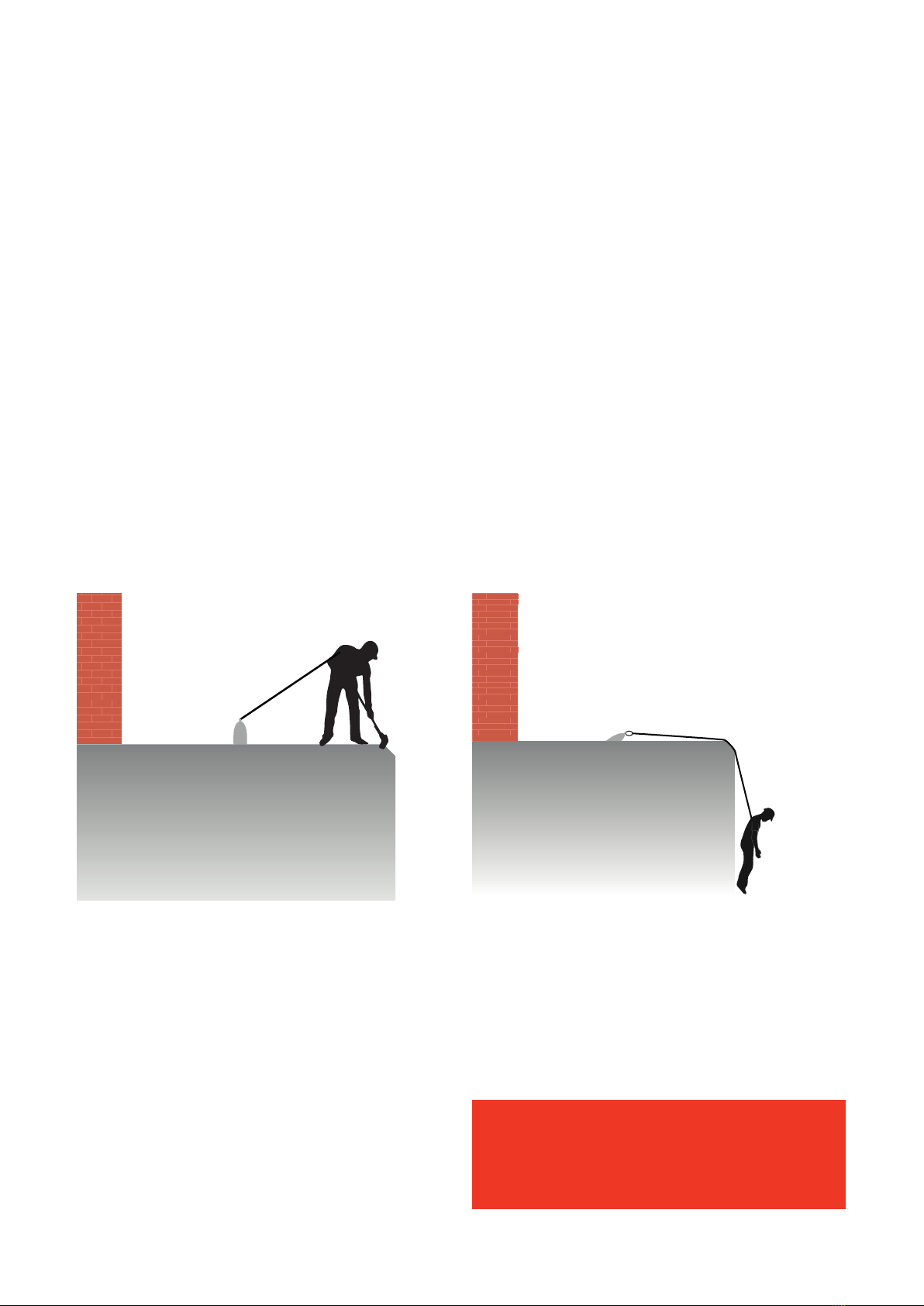
2.1 Work Restraint
Work restraint systems are the safest method of HLL
system design. Keeping the user in restraint removes the
possibility of a fall. The users path, and what they have
access to can be dictated and controlled.
The main advantages of Work restraint systems;
nNo possibility of a fall with correct PPE use
nNo need for a rescue plan
nAdjacent buildings/lower level roofs and fall clearances
do not need to be factored in.
2.2 Fall Arrest
Fall Arrest systems are designed to ‘limit the
consequences of a fall should it occur’. The Soter HLL
system will arrest a user’s fall only if the required fall
clearances are sufficient.
Although Fall Arrest systems are often employed to give a
user full roof access, they come with major disadvantages
such as;
nThey do not stop a fall occurring as the user is
responsible for correct use of PPE
nThey can only be used on buildings with the required
free fall clearance from all hazards including objects
below rooflights
nA full rescue plan must be in place to return the user
to safety
It is imperative that the user(s) are familiar with the
system type installed, the correct use of the system
including specified PPE, and areas of access to enable
safe working at heights and minimising risks.
This is detailed in Section 9.0 ‘Contract Specific User
information’ which will be supplied by the recognised
installer.
If a Fall Arrest system is installed, a rescue
plan must be in place in the event of a fall
occurring, not solely relying on emergency
services alone.

4 5
3.0 Installation
Only recognised installers trained by SFS are certified to
carry out design, installation, and recertification of Soter
HLL systems. If this is not followed, use of the system
could put lives at risk.
Section 9.0 ‘Contract Specific User information’ details
the minimum information which should be provided to
support and maintain safe use of the system.
4.0 Re-certification
All Horizontal Life Line systems are required to be re-
certified at periods no greater than 12 months to keep
them in use under EN 795:2012. This period can be
reduced in high corrosion locations, or if the systems are
deemed to be in high use. This will be determined by SFS
and laid out in documentation supplied by the installer.
Re-certifications should only be carried out by competent
persons, familiar with the fundamentals of the Soter
system, and preferably those who are recognised
installers.
Unless you are a recognised Soter installer or competent
person, never attempt to repair, modify, dismantle a
system, or adjust the pre-set tension as this will invalidate
the installation and may put lives at risk.
4.1 General Maintenance
The Soter system is made entirely from stainless steel
and is designed to have a product life that outlasts the
roof itself. Although considered maintenance free, factors
such as corrosive environments and aggressive conditions
can have a detrimental effect on its appearance. In these
areas we would recommend the system is cleaned
regularly with a mild detergent and warm water and
rinsed thoroughly.
Although resistant to most environmental conditions,
we advise that care is taken to avoid contamination with
mild steel materials, paint, cement, bitumen, acids etc.
If contamination occurs, please contact SFS or your
approved installer for advice.
4.2 Warranty
SFS offer a warranty of up to 25 years for Soter products,
from date of original purchase subject to normal use,
correct installation, and regular approved re-certification.
This warranty covers the products only, not the
installation.
Each warranty must be applied for and is subject to our
standard terms and conditions*.
*available on request
5.0 Pre-Use Checks
It is recommended that a detailed log of use is kept and
referred to prior to the system being used. This should
contain information such as;
nSystem use dates
nUser(s) name and competence
nReasons for use and areas accessed
nVisual inspection comments
nPPE condition/ inspection records
This information should be kept in a safe place, with
system PPE and user equipment which can be signed out
prior to each use.
5.1 Slyder Inspection
The Slyder device is manufactured from stainless steel
and should be stored in its case away from the roof,
together with the required PPE/user equipment. This will
help ensure the Slyder remains in good condition and
away from possible contaminants.
nCheck the Slyder device for any obvious damage
nThe device should open and close freely
nThe device is ‘locked’ when a karabiner is attached
nOnly SFS should carry out maintenance on the device.
The Slyder device is the only tested traveller for use with
the Soter HLL system. This ensures the system is fully
traversable without the need to clip on or off as the user
negotiates intermediate and corner posts. Please see
section 7.0 on Slyder attachment and correct use.
Soter HLL
User Manual

6 7
Soter HLL
User Manual
5.2 System Tag/Label
A system label or tag should be clearly visible at the
access point to the system, or at the system start point.
This should be inspected prior to use and correlate with
system specific documentation supplied by the installer,
ensuring that;
nThe system is in date and certification is valid
nThe system type is detailed, and the risks
are understood
nIf the system is specified arrest, aspects such as
free fall distances have not changed
nCorrect PPE/User Equipment is being used
nThe maximum number of users is not exceeded
nSupplier contact details are available in case of queries
about the system
If tag/label is missing, or the recertification period has
been exceeded, the system should not be used until the
system has been re-certified and re-tagged as safe
for use.
CERTIFICATION TAG
Contract No.
SYSTEM TYPE
Restraint
Arrest
PPE REQUIREMENTS
No. of persons
Max lanyard length
Date installed
Inspection due
M
5.3 Documentation & Certificate
Contract/ system specific information should be
referred to prior to system use to ensure the user(s) fully
understand the following;
nAccess point(s)
nSystem layout
nSystem purpose- what areas it will allow users
to access
nSystem type and risks associated
nValid system certification
nMaximum users permitted to use the system
These documents will be supplied by the recognised
installer and are described in more detail in section 9.0.
5.4 System Inspection
If possible, before attaching to the system/accessing
the roof area carry out a visual inspection of the system.
Check that there are no obvious signs of damage such as;
nDeployed posts
nSag in the wire (where it is touching the roof)
nKinks or breaks in the wire
nServices or goods impeding the users route or resting
on the line or posts themselves.
If you have any concerns about the
products appearance, general condition of
the system, or installation, please contact
your installer and remove the system from
service until remedied.

6 7
6.0 Personal Protective Equipment
(PPE)
It is imperative that the correct PPE as detailed on both
the tag and system specific information supporting the
system are worn, and their correct use understood. It is
also recommended that PPE should be issued to one user
for their own use, wherever possible.
6.1 Harness & Lanyard Inspection
All PPE should be examined prior to use and an
examination record filled out. It is the responsibility of the
user to carry out a visual inspection of their equipment.
If there is any doubt, withdraw the equipment from
service. The withdrawn equipment should be inspected
by a competent person (other than the user) before being
returned to service. A full comprehensive inspection of
the harness and lanyards should not be greater than
6 months - with this period reduced if the equipment is
heavily used, and recorded.
6.2 Cleaning, Storage and Lifespan
Cleaning:
Harness and lanyards should be cleaned in warm water
using a mild detergent, rinsed thoroughly, and allowed
to dry naturally away from open fire or other sources of
direct heat.
Storage:
The equipment should be properly stored and transported
in the bag supplied to prevent any contact with sharp
objects and harmful substances and stored in an area
which is dry and free from direct sunlight.
Lifespan:
The lifespan of PPE is generally 10 years from date of
manufacture in unopened bags, 5-7 years from first use
(individual manufacturers may differ slightly). The working
life will be reduced through age, general wear and tear,
and frequency of use.
Inspection Checklist
3Information label should be present
3Check all webbing and stitching. There should be no evidence of cuts,
fraying or burns, the webbing should not be discoloured, and each stitch
pattern should be examined. There must be no broken stitches or cuts,
the stitch pattern should be intact.
3All metal fittings should be free from excess wear, rust, and
deformation. Ensure all moving parts are clean and if necessary,
lubricated.
3Avoid all contact with chemicals. Generally speaking, if it harms the
skin, it will harm the equipment. Evidence of chemical contamination
is shown by discolouration or powdering of the webbing.
3All markings on the product should be clear and legible
Soter HLL
User Manual
8 9
Soter HLL
User Manual
6.3 Correct Harness Wear
Harness Use:
It is recommended that the user should carry out a
suspension test in a safe place before using the harness
for the first time, in order to ensure that it is the correct
size, has sufficient adjustment and an acceptable level of
comfort.
The Harness has been designed and manufactured in
accordance with BS EN361:2002: Personal protective
equipment against falls from height- Full Body Harnesses.
The full body harness can be used as follows;
nAs part of an assembly to protect the user in a fall
from height
nUsed with a restraint lanyard to prevent the user
from falling
nUsed as part of a work positioning assembly
nUsed as part of a rescue system
In the event of the user falling from height, the intended
purpose of the harness is to hold the user in a safe and
upright position and to dissipate the resulting pressure on
the body evenly.
When used to protect the user in the event of a fall,
the harness must be used in conjunction with an
energy absorber (manufactured to BS EN355) a lanyard
(manufactured to BS EN354) and an anchorage point (to
BS EN795). The user should be aware that, usually, when
a 2 metre lanyard fitted with an energy absorber is
deployed, the length of the lanyard will increase to
3.75 metres. The user should always read the
manufacturers instructions, which accompany the lanyard
and energy absorber, to verify the exact measurements.
Before using any absorber, which is part of a fall arrest
system, check there is sufficient free fall space, clear of
hazards below the users’ feet to prevent collision with any
structures or the ground. This information should also be
detailed in contract specific documentation provided by
the installer- proving the free fall clearance is adequate.
The equipment should not be used for any other purpose,
other than which it has been designed.
The harness is manufactured from 100% polyester
webbing and thread, steel fittings, and elastic webbing
‘tidies’.
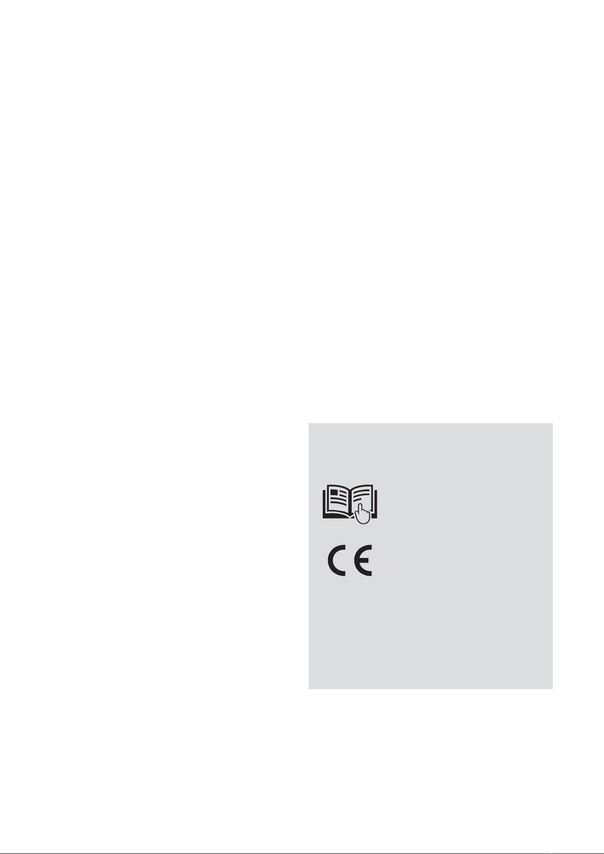
Meaning of Marks
Book Symbol:
Read the instructions for use
before using equipment
CE Symbol:
This equipment conforms
with EU
0120
ALet ter ‘A’:
‘A’ is laser marked on each
fall arrest attachment point
The equipment should not be altered or added to without
the prior written consent of the manufacturer. Should it
be re-sold outside the original country of manufacture,
then the re-seller shall provide instructions for use,
maintenance, and periodic examination in the language of
the country in which the equipment is re-sold.
If you are in any doubt about the integrity of this
equipment, remove it from use and return it to your
supervisor. The equipment should not be used again until
inspected by a competent person.

8 9
Soter HLL
User Manual
Fitting the Harness
Ref 1:
Hold the harness by the dorsal
attachment point stitched on the
back of the harness.
Ref 2:
Fit the shoulder straps ensuring that
the rear D link is on the outside of the
harness and there aren’t any twists in
the webbing.
Ref 3:
Fit the chest strap and adjust to fit.
Ref 4:
Fit the thigh straps making sure that
the straps are fitted to the correct
buckle again ensuring webbing
isn’t twisted.
Ref 5:
Adjust straps so that the rear lower
straps fit under the buttocks.
Ref 6:
Adjust the harness to achieve a
comfortable tension.
Slide the nearest elastic tidy up to
the metal fittings in place and use the
second elastic tidy to retain any
surplus webbing.

10 11
Soter HLL
User Manual
Buckle Fittings
6.4 Lanyard Connection
Whether a shock absorbing lanyard or fixed restraint
lanyard is specified, both should be connected to the user
at the dorsal attachment of the harness. It is imperative
that the correct lanyard used correlates to both the
detailed specific system information supplied by the
installer and the tag/ label on the system itself.
When using a shock absorbing lanyard, the shock
absorbing end should be connected to the dorsal
attachment. Orientation is not detrimental when using
a fixed restraint lanyard.
Always ensure that the locking mechanism on each
karabiner is fully locked.
1 2
3 4
10 11
Soter HLL
User Manual
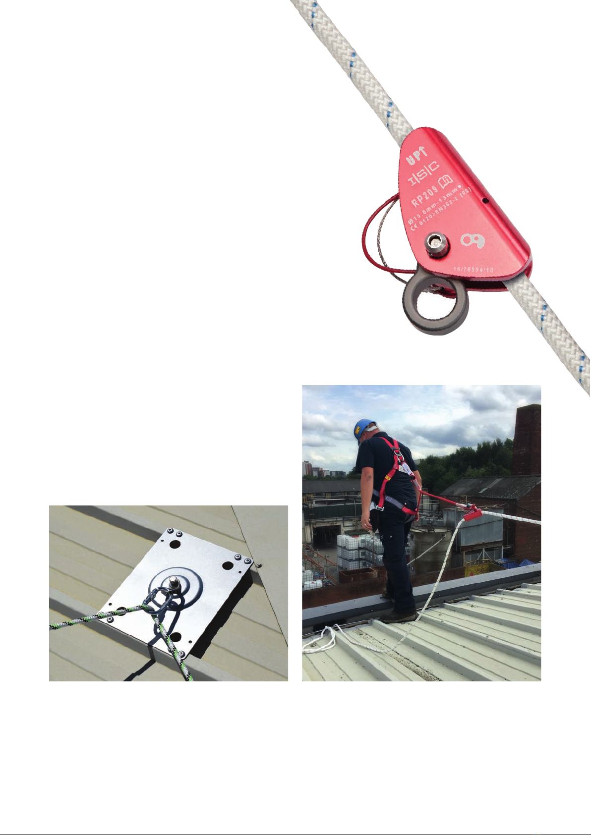
6.5 Rope and Grab Use
The use of rope and grab equipment should only be
carried out by persons competent and trained in their safe
use, due to the greater potential of a fall occurring with
an arrest system. We recommend that user(s) should go
through site specific equipment training in relation to the
system and layout installed.
In general;
nConnection to the Slyder device on the system should
be made using the karabiner at the end of the rope
itself.
nThe grab device should be attached to the rope with the
up arrow facing towards the line system
nThe free karabiner of the shock absorbing lanyard
connected to the user should then be secured through
the ring of the grab
nThe user can then, while holding the grab in one hand,
lower themselves to the area they wish to work taking
into consideration the lanyard length
nThe user needs to ensure the grab is set so that they
are using the full extent of the lanyard and neither the
lanyard or rope is slack.
nIt is recommended the user should keep the rope at the
shortest length possible at all times returning back to
the system before moving to another area of the roof,
shortening the rope as they go, to prevent a trip hazard.
If an arrest system has been installed with anti-pendulum
posts, the user must clip their rope through the karabiner
attached to the post prior to nearing any roof edge.
This will limit the possible swing of a user’s fall from an
exposed gable end.
6.6 Inertia Reels/ Blocks
Only inertia blocks tested and approved by SFS can be
used in conjunction with the Soter HLL system.
12 13
Soter HLL
User Manual
7.0 Using the System
The system is ready to be used once all documentation is
understood by the competent user(s), all pre-use checks
have been completed and the system certificate is valid.
Lone use of HLL systems is not recommended.
Two users allows for operatives to check each other’s
equipment before use and in the event of an accident,
effect a rescue.
Roof Access
Fall protection required
beyond this point.
Warnings
nIt is not advisable to the use the equipment if
pregnant or on any medication that may cause
drowsiness or make the user unsteady.
nThe device should only be used by trained or
competent persons.
nThe device is for one person only, to be used on a
fall arrest or work restraint Soter HLL system and
should not be used for any other purpose. The
rating of the system may be for multiple users,
but only one user per device.
nIt is not permitted to alter or repair the device in
anyway, without the written permission of the
manufacturer.
nThe device must only be used on certified Soter
HLL systems and be connected to the system as
shown opposite.
nThe device must be withdrawn from use should a
fall occur. If any doubt arises about the state and
condition of the device, it should be returned to
SFS or be confirmed in writing by a competent
person that the device is still fit for purpose.
nOnce the device is locked onto the HLL system it
should be checked that the device cannot come
away from the wire rope without the removal
of the karabiner and unlocking the device. This
check ensures that the device has not been
subjected to a fall and that the gap is still within
tolerance.
nThe device is manufactured from 316 stainless
steel, and requires no maintenance, but should be
checked for any damage prior to use.
nIt should be transported and stored in suitable
packaging to prevent damage and kept away from
corrosive materials.
7.1 Accessing the System
The unique design of the Slyder device allows for
attachment/ detachment from the line at any point.
The system should be accessed from the designated
point, allowing the user to check the information tag and
date of last inspection before use.
Where access is being gained by use of a MEWP or
external ladder, care should be taken to ensure the user
is attached to an anchor point during access and egress
of the system at all times. This can be achieved by using
a second/ split leg lanyard and a loose leg strop from the
main system. The user may then traverse connected, on
to the main system and connect their Slyder device.
7.2 Slyder Device
nThe Slyder Device is a mobile anchor, designed for
use with the Soter HLL System as a one person work
restraint or fall arrest device
nThe device must be used with the following PPE
equipment; Full Body Safety Harness along with a fixed
lanyard for work restraint systems or a shock absorbing
lanyard for fall arrest systems.
nThe lanyard must be connected to the device as shown
in the illustrations on the following page.
12 13
Soter HLL
User Manual
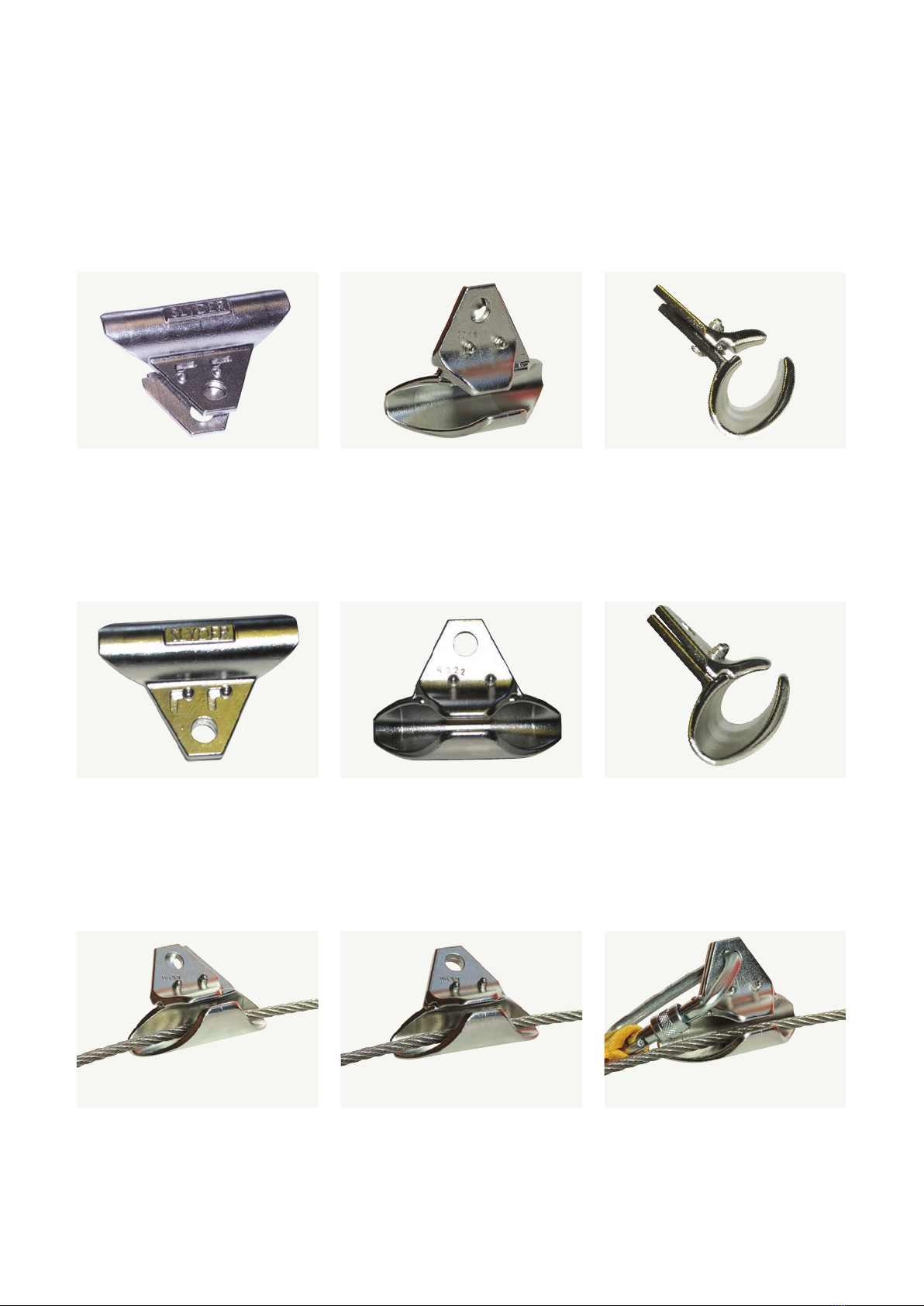
Figure 1 shows the device open
(top view) to allow connection to the
wire rope.
Figure 2 shows the increase between
the jaws of the device (bottom view).
Figure 3 shows the offset of the jaws
and the interlocking section of the
two parts.
Figure 4 shows the device closed (top
view) without a karabiner.
Figure 5 shows the decrease between
the jaws when closed.
Figure 6 shows everything in line with
reduced gap when closed.
Figure 7 shows part closed on the
wire but not locked.
Figure 8 shows fully closed ready for
locking onto the wire rope.
Figure 9 shows fully closed and
locked with the karabiner.
Soter Device Operation
Soter Device closed
Soter Device open
Soter Device open, closed, locked with karabiner on line
14 15
If a Fall Arrest system is installed, a rescue plan
must be in place in the event of a fall occurring,
without relying on emergency services alone.
Soter HLL
User Manual
8.0 After a Fall
It is imperative that the building owner has the means
to recover a user in the event of a fall, otherwise an
arrest system is not a safe means of fall protection and a
restraint system should be offered instead.
8.1 Rescue and Emergency Procedure
It is strongly recommended that a written emergency
and rescue plan is devised by the building owner.
Those responsible for rescue should be trained to the
required level. This should include the understanding and
treatment of presyncope symptoms (Light headedness;
nausea; flushing sensations; tingling or numbness of the
arms or legs; anxiety; visual disturbance; or a feeling they
are about to faint) or syncope (unconsciousness) in the
fallen person.
More information of dealing with the above can be found
on the HSE’s website www.hse.gov.uk
As noted previously, the best practice for roof access is
not to do it alone. Having 2 workers at all times allows one
to aid the rescue of the other, or raise the alarm quickly
and summon help.
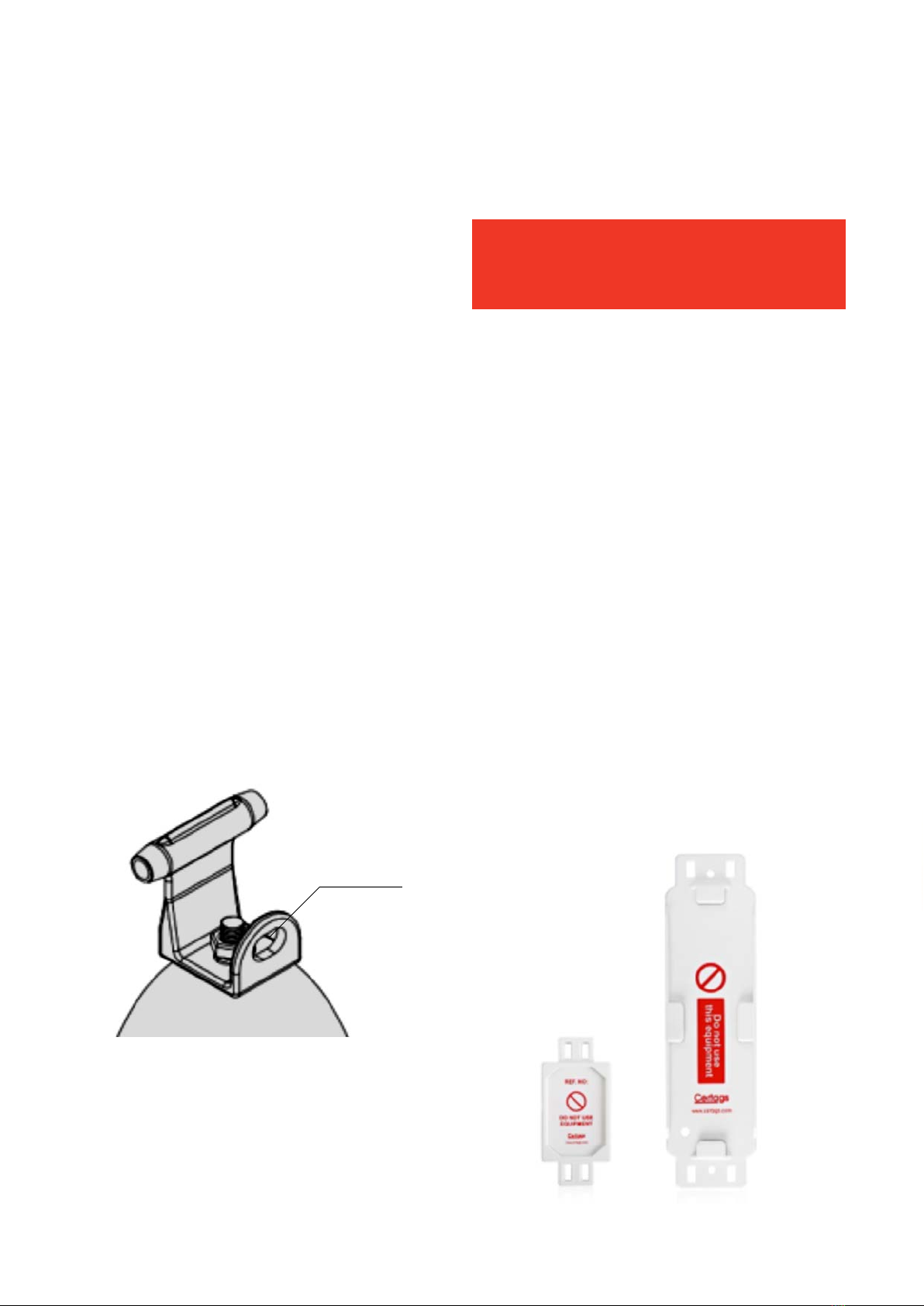
8.2 System Re-commissioning
Should a fall occur on the system it should be immediately
taken out of use, removing the system label/ tag, to show
the ‘do not use’ symbol.
The system then needs to be serviced and re-certified by
a recognised Soter installer before it’s used again.
7.3 Tips and Tricks / Ease of Use
The Soter HLL system has been specifically designed so
that it is simple and easy to use.
Due to the way the Slyder device has been designed it
allows the user to traverse the whole system without
the need to disconnect. The Slyder will pass over all
intermediate brackets (even up to 45 degrees) and corner
posts.
To traverse posts and brackets with ease, the user should
walk alongside the system and using one hand hold their
lanyard so that the Slyder device remains level with a
degree of sag in the lanyard itself. This will ensure the
Slyder glides over each bracket.
7.4 Crossing Points
The unique passing loop on the intermediate bracket
allows users connected to the same line the ability to
pass each other without the need to fully detach from the
line.
One user should use the spare leg on their twin legged
lanyard and connect their karabiner to the passing loop
on the intermediate bracket. Once connected they are
safe then to remove their Slyder device from the line
itself. This will allow the other user to pass. The first user
can then re-attach their Slyder device to the line before
removing their spare lanyard from the passing loop.
This ensures neither user is disconnected from the
system at any time.
This should only be done in a safe area, away from any
potential fall hazards (i.e roof lights).
Passing loop

14 15
Soter HLL
User Manual
9.0 Contract Specific
User Information
It is important that the system installer provides specific
user information to support this user manual, also known
as an O&M Manual which should lay out the following in
detail to allow safe use of the system;
nClient, location, project name, address
nSystem layouts - types, reason and area system gives
access to, access point(s)
nValid Test Certificate including installation
completion date
nPPE & System Use Record
nRisk Assessment

Technical advice and sales service
SFS Ltd.
Division Construction
153 Kirkstall Road
UK-Leeds, LS4 2AT
Tel +44 1924 472 251
Fax +44 1924 440 237
www.sotersafetysystems.com
www.sfsintec.biz/uk
SFS:
Your strong partner
SFS is an international company with over
50 years experience of manufacturing innovative fastening
systems. Our customers profit from:
nA solution oriented culture to create customer value
nIn-house development and production in Europe,
North America and Asia
nExemplary process and technology competence
nLocal presence linked to an international network
SFS: Assuring innovation and quality!
Version 1.0
This manual suits for next models
1
Table of contents
Other SFS Safety Equipment manuals


Popular Safety Equipment manuals by other brands


DBI SALA
DBI SALA 3M 3400130 User instructions

BUCKINGHAM MFG
BUCKINGHAM MFG BuckSqueeze 483 Series Instructions & warnings

Reliance
Reliance Roto-Loc 44 Series Instructions for use

IKAR
IKAR ASS-1 Log book and instructions for use

KRATOS SAFETY
KRATOS SAFETY OLYMPE-S manual

3M
3M SEALED-BLOK 3400944 instruction manual

EUCHNER
EUCHNER MGB-L B-PN Series operating instructions

Petzl
Petzl PROGRESS ADJUST I TECHNICAL NOTICE

turck
turck IMXK12-AI01 Series quick start guide

optrel
optrel weldcap bump RCB 3/9-12 quick start guide

Petzl
Petzl ASAP'SORBER 40 Instructions for use

Tractel
Tractel CSK3 Installation, operating and maintenance manual