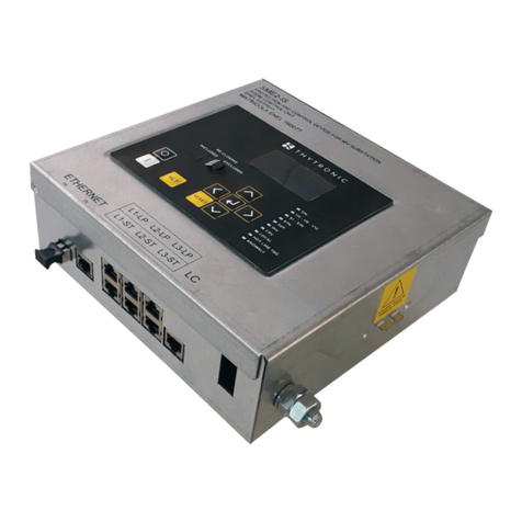
SGB VLX-S 350 M Operator's manual

Documentation
Vacuum leak detector VLX-S 350 M
For 1 up to 6 tanks with a suction line for the leak detector to
the lowest point of the interstitial space
Read the instructions before starting any work
Issued: 08/2020
Art. no.: 602702

VACUUM LEAK DETECTOR VLX-S 350 M 03/08/2020
- 2 -
Table of contents
1.General.................................................................................4
1.1.Information ...................................................................4
1.2.Explanation of symbols ................................................4
1.3.Limitation of liability......................................................4
1.4.Copyright......................................................................4
1.5.Warranty conditions .....................................................5
1.6.Customer service .........................................................5
2.Safety....................................................................................6
2.1.Intended use ................................................................6
2.2.Obligations of the operating company..........................6
2.3.Qualifications ...............................................................7
2.4.Personal protective equipment (PPE)..........................7
2.5.Fundamental hazards ..................................................8
3.Technical data .....................................................................9
3.1.General data ................................................................9
3.2.Electrical data ..............................................................9
3.3.Switching values ..........................................................9
3.4.Field of application .......................................................9
4.Design and function............................................................10
4.1.System design..............................................................10
4.2.Normal mode................................................................16
4.3.Air leak .........................................................................16
4.4.Liquid leak....................................................................16
4.5.Displays and controls...................................................17
5.Installing the system...........................................................18
5.1.Basic instructions .........................................................18
5.2.Signalling unit...............................................................18
5.3.Sensor..........................................................................19
5.4.Requirements for pneumatic connection lines .............19
5.5.Establishing pneumatic connections
(between leak detector and interstitial space)..............19
5.6.Electrical cables ...........................................................20
5.7.Electrical wiring diagram ..............................................20
5.8.Installation examples....................................................22
5.9.Block diagram ..............................................................26
6.Commissioning ...................................................................29
6.1.Interstitial space leak tests...........................................29
6.2.Commissioning of the leak detector.............................29
6.3.Build-up of negative pressure up to operating
pressure .......................................................................30
6.4.Optional data transfer (only available for devices
with one display/control panel).....................................30
Table of contents

03/08/2020 VACUUM LEAK DETECTOR VLX-S 350 M
- 3 -
7.Functional check and maintenance ..................................31
7.1.General ........................................................................31
7.2.Maintenance ................................................................31
7.3.Functional check..........................................................31
7.4.Test scope ...................................................................31
8.Alarm....................................................................................33
8.1.Alarm ...........................................................................33
8.2.How to behave.............................................................33
9.Disassembly and disposal .................................................33
9.1.Disassembly ................................................................33
9.2.Disposal .......................................................................33
10.Spare parts ..........................................................................34
11.Accessories.........................................................................34
12.Appendix..............................................................................35
12.1.Dimensions and drilling pattern (device version
1 up to 4 displays)........................................................ 35
12.2.Dimensions and drilling pattern (device version
5 up to 6 displays)........................................................ 36
12.3.EU Declaration of conformity ....................................... 37
12.4Declaration of performance (DoP) ...............................38
12.5.Manufacturer’s declaration of conformity.....................38
12.6.Certification (TÜV Nord) ..............................................39
Table of contents

VACUUM LEAK DETECTOR VLX-S 350 M 03/08/2020
- 4 -
1. General
1.1. Information
These instructions provide important information on how to handle the
VLX-S 350 M negative pressure leak detector.
The VLX-S 350 M leak detector is only suitable for tanks with a suc-
tion line for the leak detector that runs to the lowest point of the inter-
stitial space.
A requirement for safety during work is the adherence to all stipulated
safety and operating instructions.
Moreover, all the regulations for the prevention of accidents and gen-
eral safety instructions which apply at the location of use of the leak
detector must be adhered to.
1.2. Explanation of symbols
Warnings in these instructions are marked with the adjacent symbol.
The signal word expresses the extent of the hazard.
DANGER:
An immediate hazardous situation which will lead to serious or even
fatal injuries if not avoided.
WARNING:
A possible hazardous situation which may lead to serious or even fa-
tal injuries if not avoided.
CAUTION:
A possible hazardous situation which may lead to minor or light inju-
ries if not avoided.
Information:
Indicates tips, recommendations and information.
1.3. Limitation of liability
All information and instructions in this documentation have been com-
piled while taking into account the applicable standards and regula-
tions, state-of-the-art technology and our many years of experience.
SGB assumes no liability in case of:
Failure to adhere to these instructions
Improper use and the deployment of unqualified staff
Unauthorised modifications
Connection to systems which are not approved by SGB
1.4. Copyright
The content of these instructions, including texts, drawings, images
and other illustrations, are protected by copyright and subject to com-
mercial property rights. All forms of misuse are prosecutable.
General

03/08/2020 VACUUM LEAK DETECTOR VLX-S 350 M
- 5 -
1.5. Warranty conditions
We provide a 24-month warranty for the VLX-S 350 M leak detector
according to our Terms and Conditions, starting from the day of in-
stallation.
The warranty period ends 27 months after the date of sale at the latest.
Before a warranty claim can be made, the functional report/test report
that details the first commissioning by trained staff must first be sub-
mitted.
The serial number of the leak detector must also be specified.
The warranty is rendered null and void in the event of:
- faulty or improper installation
- improper operation
- changes/repairs without the manufacturer’s consent.
Our warranty does not include parts, which may be perished prema-
ture due to their consistence or category of usage (e.g. pumps,
valves, gaskets, etc.). Furthermore, we are not liable for defects or
corrosion damages caused by humid or inappropriate installation en-
vironments.
1.6. Customer service
Our customer service department is available to provide you with fur-
ther information.
A list of contact persons can be found online at sgb.de or on the type
plate on the indicator unit.
General

VACUUM LEAK DETECTOR VLX-S 350 M 03/08/2020
- 6 -
2. Safety
2.1. Intended use
Only use the VLX-S 350 M leak detector for interstitial spaces which
are resistant to negative pressure up to at least 800 millibars, as
part of double-walled tanks with a maximum constructed height of 3
metres or double floors of flat bottom tank constructions.
Depending on its design, the VLX-S 350 M leak detector is suita-
ble for the monitoring of between one and six tank interstitial
spaces.
The tank has a suction line to the lowest point of the interstitial
space for evacuation / emptying the interstitial space.
The signalling unit is mounted outside the Ex-zone (potentially ex-
plosive zone)
Internally (pneumatic side), the sensor for the VLX-S 350 meets
the requirements of category 1, thus connection to suitable intersti-
tial spaces (Zone 0, 1, 2 or outside the Ex-zone)
Classification of potential vapour-air mixtures emanating from
stored goods into explosion groups II A up to II B and temperature
classes T 1 up to T4.
Earthing/equipotential bonding as per applicable regulations
(e.g. EN 1127).
Leak tightness of the interstitial spaces as per this documentation
The total volume of every individual interstitial space does not ex-
ceed 8000 litres.
Ambient temperature range for sensor: -20°C to +60°C
Ambient temperature range for signalling unit: 0°C to +40°C
Empty pipe for electrical connection cables in dome shafts and
control shafts must be sealed and gas-tight
Power connection cannot be shut off
Claims of any kind made as a result of improper use are not valid.
2.2. Obligations of the operating company
The VLX-S 350 M leak detector is for commercial use. The operating
company is thus subject to the legal obligations of occupational health
and safety regulations.
Alongside the safety instructions in this documentation, all the appli-
cable regulations for safety, accident prevention and environmental
protection must be adhered to. In particular:
Compilation of a risk assessment report and implementation of its
results in an operation manual
Regular checks to make sure that the operation manual is in line
with the current regulations
Content of the operation manual includes responses to possible
alarms
Scheduling of an annual functional test
Safety
WARNING:
Danger due to
improper use

03/08/2020 VACUUM LEAK DETECTOR VLX-S 350 M
- 7 -
2.3. Qualifications
Staff must be sufficiently qualified so that they are able to recognise
and prevent possible hazards independently.
Operating companies putting this leak detector into operation should
have attended the appropriate training course provided by SGB or an
authorized representative.
National regulations must be observed.
For Germany:
Certified company qualification for assembly/installation, commission-
ing and maintenance of leak detector systems
2.4. Personal protective equipment (PPE)
Personal protective equipment must be worn during work.
Wear the safety clothing and equipment required for the respec-
tive work
Adhere to and follow the signs relating to PPE
Keep a long in the “Safety Book”
Wear a high-visibility vest
Wear safety shoes
Wear a safety helmet
Wear safety gloves (where necessary)
Wear safety goggles (where necessary)
2.4.1 Personal protective equipment on systems that could present the risk of potentially explo-
sive atmospheres
The information described here relates above all to the safety of work
on systems that could present the risk of potentially explosive atmos-
pheres.
WARNING:
Risk to personnel
and the environ-
ment due to insuffi-
cient qualifications
Safety

VACUUM LEAK DETECTOR VLX-S 350 M 03/08/2020
- 8 -
If work is performed in areas where one must assume that atmos-
pheres could potentially be explosive, then the following equipment is
essential:
Suitable clothing (risk of electrostatic charges)
Suitable tools (as per EN 1127)
Suitable gas warning device, calibrated for the respective vapour-
air mixtures (work should only be performed at a concentration
50% below the lowest explosion limit)1
Measuring device to establish the oxygen content of the air
(Ex/O–meter)
2.5. Fundamental hazards
DANGER
from electrical current
When working on the electrics of the VLX-S 350 M, it must first be
shut off and electrically isolated.
Adhere to the valid regulations relating to electrical installation,
explosion protection (e.g. EN 60 079-17) and the regulations for
the prevention of accidents.
DANGER
from potentially explosive vapour-air mixtures.
Potentially explosive vapour-air mixtures may be produced in tank in-
terstitial spaces. In certain circumstances, potentially explosive va-
pours may escape when the connections to the interstitial space are
opened.
There may be potentially explosive vapour-air mixtures in the connec-
tion lines if vapours penetrate the inner walls due to permeation or in
case of a leak.
The leak detector system must be free of gas before carrying out
work on it.
If there is a possibility of potentially explosive vapour-air mixtures, use
pumps with explosion protection to evacuate the interstitial space.
Adhere to the explosion protection regulations, e.g. BetrSichV (Di-
rective 1999/92/EC and the derived laws of the respective member
states) and/or others.
DANGER
from working in shafts.
Leak detectors are mounted outside the manholes. The pneumatic
connections to the interstitial spaces are usually installed in dome
shafts or other shafts. Thus, the shaft is to enter for mounting.
Before entering shafts, the relevant safety measures must be taken,
and shafts must be free of gas and have sufficient oxygen.
1
Other percentage values may be stipulated by factory-specific or country-specific regulations.
Safety

03/08/2020 VACUUM LEAK DETECTOR VLX-S 350 M
- 9 -
3. Technical data
3.1. General data
Dimensions and drilling pattern see Chap. 12.1, 12.2
Storage temperature range -30°C to +60°C
Sensor application temperature range -20°C to +60°C
Accuracy of sensor 2% FK ≜20 mbar
Signalling unit application temperature range 0°C to +40°C
Protection class of leak detector device IP 30
Weight Version with 1 display 1.2 kg
Version with 4 displays 2.1 kg
Version with 6 displays 5.6 kg
3.2. Electrical data
Voltage supply: 100 to 240 V AC
optional 24 V DC
Terminals 5, 6, external signal: 24 V DC, 2 A
(only for devices with 1 display)
Terminals 11 to 13 (floating): DC ≤25 W or AC ≤50 VA
Terminals 17 to 19 (floating): DC ≤25 W or AC ≤50 VA
Terminals 21, 22, pressure sensor
Fuse protection: max. 10 A
Overvoltage category 2
3.3. Switching values
For VLX-S 350 M
(relative negative pressure)
Alarm ON > 350 mbar
Alarm OFF < 400 mbar
Recommended negative pressure for operation: 700 mbar
3.4. Field of application
Monitoring of suitable double-walled tanks for storage of mineral oil
products which are usually used at service stations
(Tanks suitable for leak monitoring are sufficiently leak-tight, have a
suction line for the leak detector running to the lowest point of the in-
terstitial space and are sufficiently resistant to negative pressure)
Technical data

VACUUM LEAK DETECTOR VLX-S 350 M 03/08/2020
- 10 -
4. Design and function
4.1. System design
The VLX-S 350 M leak detector comprises a signalling unit and an
installation kit for the tank. The signalling unit features either 1, or 2 –
4 or 5 – 6 display/control panels for the monitoring of 1 – 6 tanks.
A display/control panel for an individual tank comprises a display for
the digital pressure display, an acknowledge button for the acoustic
alarm signal, a green operating light and a red alarm lamp.
The installation kit comprises a pressure sensor with explosion pro-
tection and a shut-off valve for the suction connection.
Signalling unit with 1 display/control panel:
01 “Alarm” signal lamp, red
09 “Operation” signal lamp, green
71 “Mute” button
103 Display with digital pressure reading
Design and function
103
09
71
01

03/08/2020 VACUUM LEAK DETECTOR VLX-S 350 M
- 11 -
Signalling unit of this device version with 4 display/control panels
01 “Alarm” signal lamp, red
09 “Operation” signal lamp, green
71 “Mute” button
103 Display with digital pressure reading
Signalling unit of this device version with 6 displays/control panels
01 “Alarm” signal lamp, red
09 “Operation” signal lamp, green
71 “Mute” button
103 Display with digital pressure reading
103
09
71
01
Design and function
09
71
103
01

VACUUM LEAK DETECTOR VLX-S 350 M 03/08/2020
- 12 -
Interior view of this device version with one display/control panel and a DTM
that is only available for this variant, as used for the LOD (Leak Online Diag-
nosis Service), with:
01 “Alarm” signal lamp, red
09 “Operation” signal lamp, green
31 Terminal strip
69 Buzzer
71 “Mute” button
75 Display circuit board
76 Main circuit board
149 Data transfer module (DTM)
75
01
09
76
71
69
149
31
Design and function

03/08/2020 VACUUM LEAK DETECTOR VLX-S 350 M
- 13 -
Interior view of this device version with four display/control panels, featuring:
31 Terminal strip
69 Buzzer
75 Display circuit board
76 Main circuit board (yellow: 1, red: 2, blue: 3, green: 4)
139 Membrane keypad (yellow: 1, red: 2, blue: 3, green: 4)
Design and function
139
76
69
75
31

VACUUM LEAK DETECTOR VLX-S 350 M 03/08/2020
- 14 -
Interior view of this device version with six display/control panels, featuring:
31 Terminal strip
69 Buzzer
75 Display circuit board
76 Main circuit board (yellow: 1, red: 2, blue: 3, green: 4)
139 Membrane keypad (yellow: 1, red: 2, blue: 3, green: 4)
Design and function
139
75
76
31

03/08/2020 VACUUM LEAK DETECTOR VLX-S 350 M
- 15 -
Installation kit:
Installation kit with:
02 Shut-off valve
68 Suction connection (with protective cap)
100 Measurement connection to interstitial space
101 Suction connection to interstitial space
102 Pressure sensor (designed as explosion-proof)
Design and function
68
102
02
101
100

VACUUM LEAK DETECTOR VLX-S 350 M 03/08/2020
- 16 -
4.2. Normal mode
Normal mode status is established during commissioning for each
tank interstitial space by generating negative operating pressure us-
ing an external installation pump.
The negative pressure in the interstitial space is measured by the
sensor and displayed on the digital display of the signalling unit (for
devices with several displays, several interstitial spaces can be con-
nected and their negative pressure levels showed on the correspond-
ing displays.)
Any leaks will result in a drop in negative pressure.
Very high demands are placed on the leak tightness of the interstitial
space(s) and the connecting line in order to ensure fault-free opera-
tion.
If the operating lamp goes out, it means there is an interruption in the
voltage supply and the alarm relay is de-activated.
4.3. Air leak
If there is a leak in the outer wall (above the ground water) or in the
inner wall above the liquid level, air is sucked into the interstitial
space due to the prevailing negative pressure. The negative pressure
drops. In cases where the negative pressure drops to the set alarm
level, an alarm is triggered.
4.4. Liquid leak
In the event of a liquid leak, liquid enters the interstitial space and col-
lects at the lowest point of the interstitial space.
The ingress of liquid causes the negative pressure to drop. If leaking
liquid continues to enter the interstitial space (due to the negative
pressure therein), there is a further drop in negative pressure. If the
ingress of liquid into the interstitial space is large enough to cause the
negative pressure limit to be undershot, an alarm is triggered immedi-
ately.
Note:
after a leak has occurred, there is a risk that liquid will be sucked in
when evacuating the interstitial space again.
Before re-commissioning the leak detector, any liquid that has seeped
in must be fully channelled off via the suction line.
Design and function

03/08/2020 VACUUM LEAK DETECTOR VLX-S 350 M
- 17 -
4.5. Displays and controls
4.5.1 Display
4.5.2 “Switch off acoustic alarm” function
Press the “mute” button once. The acoustic signal is switched off and
the red LED flashes.
Press the button again to switch on the acoustic signal.
This function is not available in normal mode or in case of faults.
4.5.3 “Test the optical and acoustic alarm” function
Press and hold (for approx. 10 seconds) the “mute” button. The alarm
is triggered until you release the button.
Press the button again to switch on the acoustic signal.
This function is not available in normal mode or in case of faults.
Signal lamp
Operating
status
Alarm status
Alarm, acoustic
alarm acknowl-
edged
Device
malfunction
OPERATION:
green
ON ON ON ON
ALARM:
red
OFF ON FLASHES ON
Design and function

VACUUM LEAK DETECTOR VLX-S 350 M 03/08/2020
- 18 -
5. Installing the system
5.1. Basic instructions
Before starting work, this documentation must be read and un-
derstood. In case of any doubts, contact the manufacturer.
The safety instructions in this documentation must be adhered to.
Installation work may only be performed by qualified companies.
Observe the applicable accident prevention regulations.
Adhere to the applicable regulations relating to electrical installa-
tion and explosion protection.
Feedthroughs for pneumatic and electrical connection lines,
which could create a potentially explosive atmosphere, must be
sealed gas-tight.
Before entering the control shafts, oxygen levels must be
checked and the inspection shaft must be purged.
If metal connection lines are used, it must be ensured that the
mains earth is at the same electric potential as the tank/pipe that
is to be monitored.
A number of relevant points relating to personal protective cloth-
ing and equipment are listed in Chapter 2.4.
5.2. Signalling unit
(1) Wall-mounting is generally performed using dowels and screws.
(housing dimensions and drilling profiles are illustrated in Appen-
dix 10.2)
(2) DO NOT install in potentially explosive zones.
(3) The housing is installed at a suitable position in the building or in
a weather-proof protective cabinet outdoors.
(4) The distance between the leak detector and interstitial space
must be kept as small as possible.
(5) Empty pipes must be laid for feeding the electrical connection
line to the tank.
Empty pipes must be sealed gas-tight on the tank side in order to
prevent the spread of potentially-explosive atmospheres.
Installation

03/08/2020 VACUUM LEAK DETECTOR VLX-S 350 M
- 19 -
5.3. Sensor
The sensor is installed as close as possible to the tank in combina-
tion with the angle bracket and shut-off valve (installation kit).
The sensor cable can be extended using suitable extension tech-
nology.
The maximum cable length (for 2 x 0.75 mm shielded cable) be-
tween the explosion sensor and the VLX-S 350 M leak detector
is 500 m.
The sensor cable is shielded. The shielding is not connected to the
pressure sensor. In general, shielding is not necessary. In case it
is required, extend the shielding along every cable extension and
apply it from the signalling unit to an external connection point.
Terminal boxes for potentially explosive atmospheres must be
used within an Ex-zone. e.g. SGB item no.: 220480 “EX “e” junc-
tion box with three screw-type cable ducts (M 20)”
5.4. Requirements for pneumatic connection lines
Underground metal or plastic pipes or aboveground, outdoor plas-
tic pipes must be routed in protective piping.
Clear width of 6 mm or 8 mm.
Hose/pipe thickness: 1 mm
Resistant to the stored product
At least PN 10 across the entire temperature range.
A distance of 50 m between the sensor and the interstitial space
may only be exceeded slightly, and if this is the case: Use
pipe/hose with a greater clear width, using suitable adapter pieces.
Colour designation: measuring line: red
Prevent build-up of electrostatic charges (e.g. when pulling cables).
5.5. Establishing pneumatic connections (between leak detector and interstitial space)
Select and route a suitable polyamide hose or suitable pipe.
When routing, ensure that the pipes/hoses are protected from
damage that could be caused by people entering the dome shaft.
The full cross section must remain intact; dents and kinks2are im-
permissible.
Observe earthing / equipotential bonding of metallic parts in non-
conductive connection lines.
Seal the protective pipes so that they are gas-tight in order to pre-
vent the spread of potentially explosive atmospheres through the
pipes into buildings and to prevent ingress of liquids.
Establish the respective connection (as per the illustrations in
the following images).
2
If necessary, use standard commercial moulded fittings (with the specified bending radii).
Installation
Sensor
Shut-off valve
Suction port Angle bracket

VACUUM LEAK DETECTOR VLX-S 350 M 03/08/2020
- 20 -
5.5.1 Compression fitting for metal and plastic pipes
(1) Insert a support sleeve (only plastic pipe) into the pipe end
(2) Insert the pipe (with support sleeve) as far as it will go
(3) Tighten the screw connection by hand until there is a resistance,
then turn 1 ¾ turn further with the wrench
(4) Unfasten the nut
(5) Tighten the nut by hand until it touches noticeably
(6) Final assembly of the screw connection by tightening ¼ turn
5.5.2 Quick screw connection for polyamide hose:
(1) Cut the PA hose to length at a right angle
(2) Unscrew the union nut and push it over the pipe
(3) Push the hose onto the nipple up to the start of the thread
(4) Tighten the union nut by hand
(5) Tighten the union nut with a screw wrench until there is a notice-
able increase in resistance (approximately 1 to 2 turns).
5.6. Electrical cables
Mains connection:
Suggested cable: Ölflex Classic 100
2.5 mm2without cable-end sleeve
1.5 mm2with cable-end sleeve and plastic collar
Floating contacts and external signal
Suggested cable: Ölflex Truck 1700
1.5 mm2without cable-end sleeve
0.75 mm2with cable-end sleeve and plastic collar
5.7. Electrical wiring diagram
(1) Lay firmly, i.e. no plug connections or switch connections.
(2) Observe the regulations of the electricity supplier3.
(3) Terminal assignment: (see also 5.9 block diagram)
3
For Germany: VDE regulations also apply
Installation
Table of contents
Other SGB Security Sensor manuals
SGB
SGB DLR-GS Series Operator's manual
SGB
SGB VLR Series Operator's manual
SGB
SGB DLR-G Operator's manual
SGB
SGB DLR-P CV Series Operator's manual

SGB
SGB VLR Series Operator's manual
SGB
SGB DL-4000 Series Operator's manual
SGB
SGB VLX Ex Series Operator's manual
SGB
SGB DLR-P User manual
SGB
SGB VLXE Ex M Series Operator's manual
SGB
SGB DL Series User manual
SGB
SGB VLX A-Ex Series User manual
SGB
SGB VL Series Operator's manual
SGB
SGB VL 330 Installation and operating instructions
SGB
SGB DLR-2 Series Operator's manual
SGB
SGB DLR-GS Operator's manual

SGB
SGB VL Series Operator's manual
SGB
SGB DLR-P Series Operator's manual
SGB
SGB VLXE Series Operator's manual
SGB
SGB VL-H9 User manual

SGB
SGB DL Series User manual
