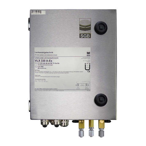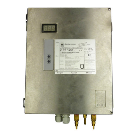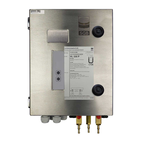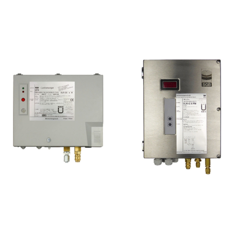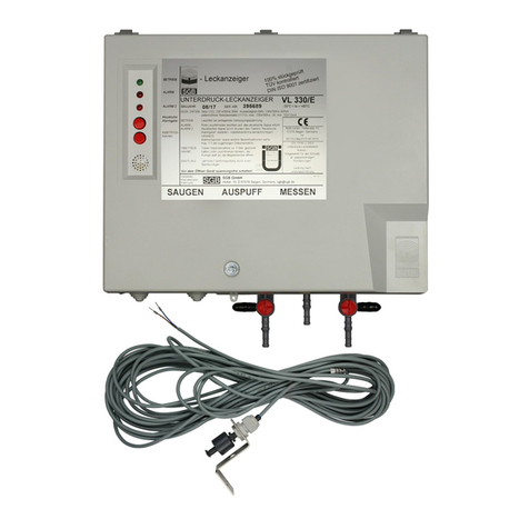
VACUUM LEAK DETECTOR VLX ../A-Ex
29/06/2018
(4) Close the condensate traps.
(5) a) Set three-way valves 20 and 21 to position I. (P-096 000)
b) V4A Version: set measuring and suction line side stop cock to position 1. (P-098 000)
c) MV Version: Additionally activate „start up“ switch if the leak detector alarm in active.
(6) Open the stop cocks on the interstitial space side.
6.4.3 Checking the Free Passage of Air in the Interstitial Space
(1) a) Connect measuring instrument to three-way valve 21, then set to position III. (P-096 000)
b) V4A Version: Connect the measuring instrument to the stop cock on the measuring line
side, and set to position 2. (P-098 000)
(2) For tanks and pipes per installation example L/M -3:
a) Set three-way valve 20 to position IV. (P-096 000) b) V4A Version: open suction line side
stop cock (P-098 000)
For pipes as per installation example L/M-1 and L/M-2: Open the test valve at the end
opposite the leak detector; in case of multiple pipe interstitial spaces, the test valves must
be opened sequentially at the end opposite the leak detector.
(3) Check if the measuring instrument registers a vacuum drop. If no pressure drop occurs,
locate and correct the cause.
(4) Close three-way cock 20 in position I, or suction line side stop cock (V4A Version) of test
valve(s) respectively.
(5) a) Set three-way valve 21 to position I. (P-096 000)
b) V4A Version: Close measuring line side stop cock. (P-098 000)
(6) Remove the measuring instrument.
6.4.4 Testing the Switch Values with the Interstitial Space
(1) Connect the measuring instrument to three-way valve 21, position III. (P-096 000)
b) V4A Version: Connect the measuring instrument to the stop cock on the measuring line
side, and set to position 2. (P-098 000)
(2) For tanks and pipes per installation example L/M -3:
a) Ventilate with three-way valve 20 (position III). (P-096 000)b) V4A Version: Ventilate with
the suction line side stop cock (position 2) (P-098 000)
For pipes as per installation example L/M-1 and L/M-2: Open the test valve at the end of
the interstitial space opposite the leak detector. In case of multiple pipes, the leak detector-
side stop cocks of the interstitial spaces not included in the test can be closed.
(3) Check switch values “Pump ON” and “Alarm ON” (with visual and audible alarm, if
available). Record the values.
(4) Activate ”Audible Alarm” switch.
(5) Set three-way valve 20 to position I and close suction line side stop cock (V4A Version) or
test valve (in MV version, switch “Start Up” valve) and check switch values "Alarm OFF”
and "Pump OFF”. Record the values.
(6) The unit passes the test if the measured switch values fall within the specified tolerance.
(7) Open any stop cocks that were closed prior to the test.
(8) a) Set three-way valve 21 to position I. (P-096 000)
b) Set measuring line side stop cock to position 1. (P-098 000)
(9) Remove the vacuum gauge.


