Gree XE70-33/H User manual

Owner's Manual
Original Instructions
Wired Controller XE70-33/H

To Users
Thank you for selecting Gree’s product. Please read this instruction manual
carefully before installing and using the product, so as to master and correctly use the
product. In order to guide you to correctly install and use our product and achieve
expected operating effect, we hereby instruct as below:
(1) This appliance is not intended for use by persons (including children) with
reduced physical, sensory or mental capabilities, or lack of experience and
knowledge, unless they have been given supervision or instruction
concerning use of the appliance by a person responsibility for their safety.
Children should be supervised to ensure that they do not play with the
appliance.
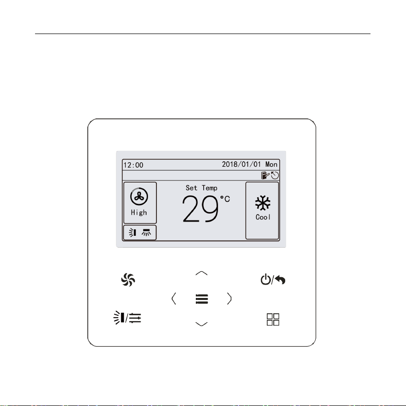
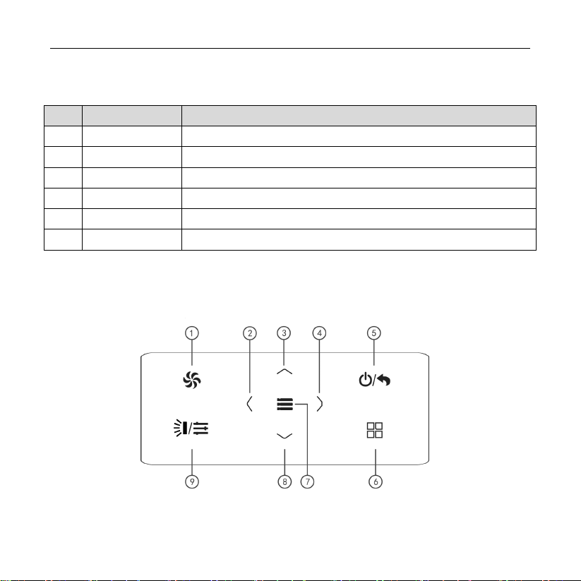
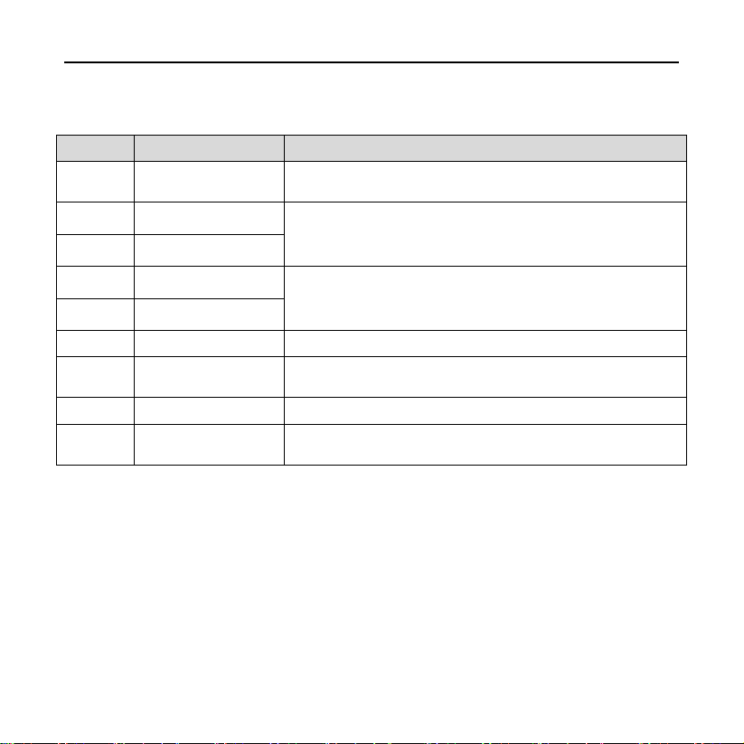
(2) This instruction manual is a universal manual, some functions are only
applicable to particular product. All the illustrations and information in the
instruction manual are only for reference, and control interface should be
subject to actual operation.
(3) In order to make the product better, we will continuously conduct
improvement and innovation. We have the right to make necessary revision
to the product from time to time due to the reason of sales or production,
and reserve the right to revise the contents without further notice.
(4) For personal injury or property loss and damage caused by improper
operation such as improper installation and debugging, unnecessary
maintenance, violation of related national laws and rules and industrial
standard, and violation of this instruction manual, etc., we will bear no
liability.
(5) The final right to interpret for this instruction manual belongs to Gree
Electric Appliances, Inc. of Zhuhai.

Contents
1 Safety Notices (Please be sure to abide them) .................1
2 Operation Notices................................................................1
3 Instructions to Appearance and Display ...........................3
3.1 LCD of Wired Controller.................................................................4
3.2 Instruction for LCD of Wired Controller ..........................................5
4 Buttons .................................................................................5
4.1 Silkscreen of Buttons.....................................................................5
4.2 Instruction for Buttons....................................................................6
5 Instructions for Status Column ..........................................7
6 Installation and Commissioning.......................................10
6.1 Instruction of wired controller.......................................................11
6.2 Engineering Debugging of Air Conditioner...................................19
7 Operational Instructions of Air Conditioner ....................36
7.1 ON/OFF .......................................................................................37
7.2 Setting of Modes..........................................................................37
7.3 Setting of Temperature ................................................................38
7.4 Setting of Fan Speed ...................................................................39
7.5 Setting of Swing Function ............................................................40
7.6 Setting of Functions.....................................................................42
7.7 Gate-control Function ..................................................................49

7.8 Independent Swing* ....................................................................50
8 Operational Instructions of ERV+DX Coil Unit................52
8.1 ON/OFF .......................................................................................52
8.2 Setting of Modes..........................................................................53
8.3 Setting of Temperature ................................................................54
8.4 Setting of Fan Speed ...................................................................54
8.5 Setting of Control Modes .............................................................55
8.6 Setting of Functions.....................................................................56
9 Instructions to General Operation....................................58
9.1 Setting of Schedule .....................................................................58
9.2 Service Hotline ............................................................................60
9.3 Setting of Language ....................................................................62
9.4 Setting of Sound ..........................................................................62
9.5 Setting of Date and Time .............................................................62
9.6 Long-distance Shielding ..............................................................62
9.7 Inquiry of Indoor Temperature with One Button ...........................63
10 Display of Errors..............................................................63
10.1 Error Code List of ODU..............................................................64
10.2 Error Code List of IDU ...............................................................66
10.3 Code List for Debugging ............................................................68
10.4 Code List for Status ...................................................................69

Wired Controller XE70-33/H
1
1 Safety Notices (Please be sure to abide them)
WARNING: If not abide them strictly, it may cause severe damage to the
unit or the people.
NOTE: If not abide them strictly, it may cause slight or medium damage to
the unit or the people.
This sign indicates that the items must be prohibited. Improper operation
may cause severe damage or death to people.
This sign indicates that the items must be observed. Improper operation
may cause damage to people or property.
WARNING!
This product can’t be installed at corrosive, inflammable or explosive environment or
the place with special requirements, such as kitchen. Otherwise, it will affect the
normal operation or shorten the service life of the unit, or even cause fire hazard or
serious injury. As for the above special places, please adopt special air conditioner
with anti-corrosive or anti-explosion function.
2 Operation Notices
The power supply for all indoor units must be unified.
Prohibit installing the wired controller at wet or sunshine places.
Do not knock, throw or frequently disassemble the wired controller.
Do not operate the wired controller with wet hands.

Wired Controller XE70-33/H
2
When the system mode priority is the master-slave mode, in one system network,
you must set one indoor unit as the master indoor unit, Other indoor units are slave
indoor units .
When the system mode priority is the master-slave mode, the operation mode of
the system is basing on that of the master indoor unit. The master indoor unit can
be set to any mode (including auto mode), while the slave indoor unit can’t set to
the mode that conflicts with the system mode.
When the system mode priority is: Cooling mode is prioritized, heating mode is
prioritized, first-set mode is prioritized, or last-set mode is prioritized. The indoor
unit can be set to any mode (excluding auto mode). The indoor unit will
automatically switch to the system mode, when the operation mode of the indoor
unit conflicts with the system operation mode.
When the system mode priority is the voting mode (indoor unit’s capacity is
prioritized / number of indoor units is prioritized). The indoor unit can be set to any
mode (excluding the auto mode). The indoor unit will be stopped, when the
operation mode of the indoor unit conflicts with the system operation mode after
voting.
System mode priority defaults to master-slave mode, and only certain units have
other system mode priorities.
When two wired controllers control one (or more) indoor unit(s), the address of
wired controller should be different.

Wired Controller XE70-33/H
3
Functions with “*” are optional for indoor units. If a function is not included in an
indoor unit, wired controller can’t set the function, or setting of this function is
invalid to the indoor unit.
3 Instructions to Appearance and Display
Fig. 3.1Outline of wired controller

Wired Controller XE70-33/H
4
3.1 LCD of Wired Controller
Fig. 3.2LCD of air conditioner wired controller
Fig. 3.3 LCD of ERV+DX Coil unit wired controller

Wired Controller XE70-33/H
5
3.2 Instruction for LCD of Wired Controller
Table 3.1
No.
Name
Instruction
1 Status It is for displaying date, time and the activated functional icon
2 Mode It is for displaying operating mode
3
Temperature
It is for displaying the temperature
4 Swing It is for displaying the current swing status
5 Fan speed It is for displaying the fan speed
6
Control mode
It is for displaying the control mode of the ERV+DX Coil unit
4 Buttons
4.1 Silkscreen of Buttons
Fig. 4.1 Silkscreen of buttons

Wired Controller XE70-33/H
6
4.2 Instruction for Buttons
Table 4.1 Instruction for Buttons
No.
Name
Function
1 Fan Switch fan speed: Auto, Low, Med. Low, Medium,Med. High,
and High
2 Left Turn page
Move the cursor
Set and view parameters
4 Right
3 Up Set the operating temperature of indoor unit
Move the cursor
Set and view parameters
8 Down
5 ON/OFF/Return Turn on/off the unit and return to the previous page
6 Mode Switch the operating mode: Auto, Cool, Dry, Fan, Heat, Floor,
3D Heat, etc.
7 Menu/OK Select mode and confirm parameters
9 Swing/Control Set the swing status of air conditioner or control mode of
ERV+DX Coil system
NOTES:
①When the button operation is invalid, the beeper beeps for twice to prompt.
②If there is no operation in wired controller for consecutive 20 seconds, the
backlight turns off and returns to the homepage.

Wired Controller XE70-33/H
7
5 Instructions for Status Column
Table 5.1 Instruction for Status Column of AC
Icon
Name
Instruction
Master
Display when the current indoor unit connected by the wired
controller is master indoor unit (the icon will not be displayed
when the wired controller connects to heat recovery unit)
Group control Display when one wired controller controls multiple indoor units at
the same time
Slave wired
controller
It means the current wired controller is a slave wired controller
(address of wired controller is 02)
Shielding It means shielding status
Card pulling The gate control card is pulled out
Lock Lock status
Invalid operation Display when the operation is invalid
Error Display when error occurs
Memory Memory status (when the unit is re-energized after power failure,
the indoor unit will resume to the setting status)

Wired Controller XE70-33/H
8
Icon
Name
Instruction
Defrost Defrosting status of outdoor unit
Schedule Display when schedule function is activated
Clean The status for reminding of cleaning the filter
Table 5.2 Instruction for Status Column of ERV+DX Coil IDU
Icon
Name
Instruction
Master
Display when the current indoor unit connected by the wired
controller is master indoor unit (the icon will not be displayed
when the wired controller connects to heat recovery unit)
Group control Display when one wired controller controls multiple indoor units at
the same time
Slave wired
controller
It means the current wired controller is a slave wired controller
(address of wired controller is 02)
Shielding It means shielding status
Card pulling The gate control card is pulled out
Lock Lock status

Wired Controller XE70-33/H
9
Icon
Name
Instruction
Invalid operation Display when the operation is invalid
Error Display when error occurs
Memory Memory status (when the unit is re-energized after power failure,
the indoor unit will resume to the setting status)
Defrost Defrosting status of outdoor unit
Schedule Display when schedule function is activated
Clean The status for reminding of cleaning the filter
Humidification
(Some models are
with humidification
function.)
Humidification function is activated
Energy recovery It means the current energy recovery function is valid
Bypass It means the current bypass function is valid
Air discharge Air discharge mode

Wired Controller XE70-33/H
10
6 Installation and Commissioning
Unit:mm
Fig. 6.1 Dimension of Wired Controller
Fig. 6.2 Parts and Components of Wired Controller

Wired Controller XE70-33/H
11
No. 1 2 3 4
Name Panel of wired
controller
Tapping screw ST3.9X25
MA Screw M4×25
Soleplate of
wired
controller
QTY 1 3 2 1
6.1 Instruction of wired controller
6.1.1 Requirements for model selection of communication wire
Fig. 6.3 Length of communication wire

Wired Controller XE70-33/H
12
Wire material
type
Total length of
communication
line between
indoor unit and
wired controller
L (m/feet)
Wire size
(mm2/AWG)
Material
standard Remarks
Light/
Ordinary
Polyvinyl
chloride
sheathed cord.
(60227 IEC 52
/60227 IEC 53)
L≤250m
(L≤820-1/5feet)
2×0.75
mm2~2×
1.25 mm2
(2×AWG18~
2×AWG16)
IEC
60227-5:2007
(1) Total length of
communication line
can't exceed 250m
(820-1/5feet).
(2) The cord shall be
Circular cord (the cores
shall be twisted
together).
(3) If unit is installed in
places with intense
magnetic field or strong
interference, it is
necessary to use
shielded wire.
NOTES:
①If the air conditioner is installed in the place with heavy magnetic field, the
wired controller must adopt shielded twisted pair.
②Communication wire material of wired controller must meet the
requirements of this instruction manual. It is not allowed to use the
communication wire not in consistent with the requirements of this
instruction manual.

Wired Controller XE70-33/H
13
6.1.2 Requirements for Installation
(1) It is not allowed to install the wired controller in the wet place.
(2) It is not allowed to install the wired controller in the place with direct
sunlight.
(3) It is not allowed to install the wired controller near the high-temperature
object or the place is likely to be spattered with water.
(4) It is not allowed to install the wired controller in the position where faces the
window to prevent working error due to the interference of the remote
controller with the same model from neighbor.

Wired Controller XE70-33/H
14
6.1.3 Requirements for Wired Connection
Network connecting methods between wired controller and indoor unit are as
below:
Fig. 6.4 one wired controller controls Fig. 6.5 two wired controllers control
one indoor unit one indoor unit

Wired Controller XE70-33/H
15
Fig. 6.6 one wired controller controls multiple indoor units simultaneously
Fig. 6.7 two wired controllers control multiple indoor units simultaneously
Instruction for wire connection:

Wired Controller XE70-33/H
16
(1) When one (or two) wired controller controls multiple indoor units simultaneously,
the wired controller can connect anyone of indoor unit. Quantity of indoor unit
controlled by wired controller is not over 16 sets, and the connected indoor unit
should be in the network of the same indoor unit. Wired controller should set the
group control of quantity of indoor unit, for setting method please see “6.2.2 Setting
of Parameters”.
(2) When two wired controllers control one (or more) indoor unit simultaneously, there
must be one master wired controller and one slave wired controller. For setting of
master and slave wired controllers please see “6.2.2 Setting of Parameters”.
Table of contents
Other Gree Controllers manuals
Popular Controllers manuals by other brands

Sony
Sony JunboTron JME-SA200 operating instructions

Honeywell
Honeywell CENTRA LINE MERLIN NX Series Installation & commissioning instructions

TB Wood's
TB Wood's X4 user manual

Synrad
Synrad UC-2000 quick start guide

Luxul
Luxul XWC-1000 quick start guide

Rockwell Automation
Rockwell Automation Allen-Bradley PowerFlex 23PFC Programming manual