Shandong BTP-2002NP User manual

USER’S MANUAL
Receipt Printer
BTP-2002NP
Shandong New Beiyang Information Technology Co., Ltd.
BTP-2002NP User’s Manual
Declaration
Information in this document is subject to change without notice. SHANDONG NEW BEIYANG
INFORMATION TECHNOLOGY CO., LTD. (hereinafter referred to as “SNBC”) reserves the right to
improve products as new technology, components, software, and firmware become available. If users
need further data about this product or have any doubt about safety issues that might arise from using it,
please feel free to contact SNBC or your local agents.
No part of this document may be reproduced or transmitted in any form or by any means, electronic or
mechanical, for any purpose without the express written permission of SNBC.
Copyright
Copyright © 2008-2009 by SNBC
Printed in China
Version 2.03
Trademarks
SNBC registered trademarks:
Warning and Caution
Warning: Items shall be strictly followed to avoid damages to body and equipment.
Caution: Items with important information and prompts for operating the printer.
The quality control system of SNBC has been approved of the following certification.
- 1 -
(DNV)ISO9001:2000
The environmental control system of SNBC has been approved of the following certification.
(DNV)ISO14001:2004

BTP-2002NP User’s Manual
BTP-2002NP has been approved of the following certification.
Contact us
Address: No.169 Huoju Rd, Weihai, Shandong, China. 264209
Hot line: +86-631-5673777
Fax: +86-631-5673778
E-mail: [email protected]
- 2 -

BTP-2002NP User’s Manual
- 3 -
Contents
General Safety Information....................................................................................................................1
1 Overview ..............................................................................................................................................2
1.1 Outline ............................................................................................................................................2
1.2 Features..........................................................................................................................................2
1.3 Model Classification ........................................................................................................................3
2 Specifications ......................................................................................................................................4
2.1 Main Specification...........................................................................................................................4
2.2 Cutter Specification.........................................................................................................................5
2.3 Electric Parameters of the Power Supply........................................................................................5
2.4 Paper Specification .........................................................................................................................5
2.5 Printing and Cutting Position...........................................................................................................6
2.5.1 Printing Position .......................................................................................................................6
2.5.2 Cutting Position ........................................................................................................................6
3 Outline and Parts.................................................................................................................................7
3.1 Outline and Parts ............................................................................................................................7
3.2 Error LED and Buzzer.....................................................................................................................8
4 Installation ...........................................................................................................................................9
4.1 Unpacking.......................................................................................................................................9
4.2 Selecting the Installation Position and Direction .............................................................................9
4.3 Grounding the Printer......................................................................................................................9
4.4 Connecting the Power Adapter .......................................................................................................9
4.5 Connecting Signal Cable ..............................................................................................................10
4.6 Connecting the Cash Drawer........................................................................................................10
4.7 Inserting the Paper Roll ................................................................................................................10
4.8 Self-test.........................................................................................................................................12
4.9 Adjusting the Paper Near End Sensor ..........................................................................................12
5 Routine maintenance ........................................................................................................................13
5.1 Cleaning the Print head ................................................................................................................13
5.2 Cleaning the Sensor .....................................................................................................................13

BTP-2002NP User’s Manual
- 4 -
5.3 Cleaning the Platen Roller ............................................................................................................13
6 Interface Signal..................................................................................................................................14
6.1 Parallel Interface...........................................................................................................................14
6.2 Serial Interface..............................................................................................................................14
6.3 RS-485 Serial Interface.................................................................................................................15
6.4 USB interface................................................................................................................................16
6.5 Ethernet Interface .........................................................................................................................17
6.6 WLAN interface.............................................................................................................................18
6.7 Signal Definition of Power Connector ...........................................................................................18
6.8 Cash Drawer Kick-out Connector .................................................................................................18
7 Troubleshooting ................................................................................................................................19
7.1 Clearing Paper Jams ....................................................................................................................19
7.2 Error LED and Buzzer...................................................................................................................20
7.3 Problem during Printing ................................................................................................................20
7.4 Printer does not work ....................................................................................................................20
8. Accessories ......................................................................................................................................21
8.1 Spill Proof Cover( SPC-2002NP) ..................................................................................................21
8.2 Wall Mount System (WMS-2002NP).............................................................................................21
8.3 Cable for PoweredUSB Connections ............................................................................................23
8.4 HERALD – Kitchen Alarm System ................................................................................................23
8.5 Cable cover and Power adapter cover..........................................................................................25

BTP-2002NP User’s Manual
General Safety Information
Before installing and using the printer, please read the following items carefully:
1. Safety instructions
Do not touch the cutter and tear-off bar of the printer.
The print head is a thermal element and it is at a high temperature during printing or just after
operation, do not touch it and its peripherals for reasons of safety.
The print head is an ESD-sensitive device. To prevent damage, do not touch either its
printing parts or connecting parts.
2. Caution
1) Install the printer on a flat and stable surface.
2) Reserve adequate space around the printer so that convenient operation and maintenance can be
performed.
3) Keep the printer away from water source, direct sunlight, strong light and heat.
4) Do not use or store the printer in a place exposed to heat or fire, moisture or other pollution.
5) Do not place the printer on a surface exposed to vibration or risk from impact.
6) Avoid exposing the printer to condensation. In case of condensation, ensure it has been
completely removed before turn on the power.
7) Connect the power adaptor to an appropriate ground outlet. Avoid sharing a single electrical outlet
with large power motors and other devices that may cause the fluctuation in voltage.
8) Disconnect the power adapter if the printer is idle for a long time.
9) Do not spill water or other electric substances (like metal) on the printer. If this happens, turn off
the power immediately.
10) Do not allow the printer to start printing when there is no paper, otherwise the print head and platen
roller will be damaged.
11) To ensure print quality and normal lifetime, use recommended or good quality paper.
12) Shut down the printer when connecting or disconnecting interface connectors to avoid damage to
the control board.
13) Set the print darkness to a lower grade as long as the print quality is acceptable. This will help to
keep the print head durable.
14) The printer should only be disassembled or repaired by a technician, who is certified by SNBC.
- 1 -

BTP-2002NP User’s Manual
- 2 -
1 Overview
1.1 Outline
¾The BTP-2002NP is a high performance thermal printer. It can be widely used for real-time
receipt printing applications, such as for POS systems, hospitality, lottery, weighing systems
etc.
¾The BTP-2002NP can be connected to computer systems via its interfaces and also offers
drivers and utilities under WINDOWS98 /NT4.0 /2000/2003/XP/Vista.
¾The BTP-2002NP can be connected to cash drawers via a RJ11 connector.
¾The following accessories are available for the BTP-2002NP (see chapter 8):
Spill proof cover SPC-2002NP: a transparent cover that fits over the printer and protects
the printer from liquid spilling in the printer. This accessory is especially suited when the
printer is used in kitchens and on bar counters.
Wall-mount system WMS-2002NP: a bracket system, which enables that the printer can
be mounted on a vertical surface like a wall.
A cable, which enables that the BTP-2002NP printer, that is equipped with a USB interface,
can be connected to a host with PoweredUSB connectors.
1.2 Features
¾Low noise and high printing speed.
¾Easy paper loading: drop in and print.
¾Easy operation and maintenance.
¾Continuous paper can be used with different paper widths.
¾Auto cutter (full cut or partial cut).
¾Cash drawer control connector.
¾Optional communication interfaces (daughter boards) .
¾Optional wall mount parts and spill proof cover.
¾Support Watermark printing.

BTP-2002NP User’s Manual
- 3 -
1.3 Model Classification
BTP-2002NP XX
a b
¾a Interface module (daughter boards)
R3:RS232 (DB25)(Standard configuration for Serial interface)
R5:RS-485(DB25)
R6:RS-485(RJ11)
R8:RS-485(RJ45)
P4:Parallel nibble mode (DB36 CENTRONICS)(Standard configuration for Parallel interface)
U:USB 1.1
U2:PoweredUSB
E:Ethernet
W:WLAN
¾b Color
I:Ivory
B:Black
S:Silver

BTP-2002NP User’s Manual
- 4 -
2 Specifications
2.1 Main Specification
Item Specification
Print method Direct thermal
Resolution 203DPI X 180DPI
Print speed Max. 200mm/s
Print width Max. 80mm
Paper type Continuous thermal paper
Bar code supported UPC-A, UPC-E, EAN-8, EAN-13, Codabar, Code39, ITF, Code128, code93
Character set Standard ASCII (12x24), compressed ASCII (9x17).
Code page 437, 850, 852, 860, 863, 865,866, 858,PC1252, katakana
Character enlargement All fonts can be enlarged vertically and horizontally up to 6x.
Character rotation (0°, 90°, 180°, 270°)
Watermark printing Support
Paper detect Photo sensors (paper end and paper near end detection)
Printer top cover position Micro switch
Print head overheating protection Thermal resistor
Download bitmap Direct bitmap print
Graphics 6 figures maximum download to a total
bitmap buffer of 12KB
Support bitmap mode and can realize
fast bitmap printing
Interface RS232, Parallel, USB, Ethernet or WLAN
Cash drawer kick-out RJ11 type connector; 1-2 cash drawers
Memory SDRAM: 2MB,FLASH: 1MB
Power supply 24V±5%DC, Mean current 2.5A, max. 8A
External power supply
Print head lifetime ≥100Km
Operating temperature and humidity 5~45℃, 20 ~ 80% RH (No dew condensation)
Storage temperature and humidity -40~55℃, ≤93%RH (40℃)
Dimensions printer 144(W)×192(D)×142(H) mm
Net weight printer 2.3 KG
Dimensions packing 290(W) X 260(D) X 210(H) mm
Weight packing 4.0 KG
Certificates granted CE, CB, GS, FCC, UL, CUL

BTP-2002NP User’s Manual
2.2 Cutter Specification
Item Parameter Remarks
Cutter type Slide cutter (Guillotine type)
Cutting time 600ms The time that one cut takes.
Cutting interval 2s 30 times/min. (Max.)
Paper type Thickness: 0.065 – 0.1mm Thermal paper or paper with the same thickness
Operation voltage 24VDC
Max. static current 1.2A 24V DC
Cutter lifetime 1,500,000 cuts Full cut or Partial cut
2.3 Electric Parameters of the Power Supply
Supply voltage: 24VDC±5%
Current consumption:
Mean: approximately 2.5A (12.5% duty ratio)
Peak: Approximately 8 A
Ripple & Noise: < 240mVp-p
Caution:
Please use the power supply that is supplied with the printer or an equivalent type.
2.4 Paper Specification
¾Paper type: thermal paper
¾Paper width:82.5±0.5mm, 80±0.5 mm, 76±0.5 mm, 69.5±0.5 mm
57.5±0.5 mm
¾Paper thickness:0.065 – 0.1mm
¾Paper roll O/D:Max. 83 mm
¾Printing surface: Outside of roll paper
¾Recommend paper:POS-grade paper with a thickness of 0.065 – 0.1mm
(Reference: Mitsubishi: F24OAC/F220-VP thermal paper)
¾Paper roll core diameter: Inside 12 mm, Outside 18mm
Caution:
Please use the recommended paper type or its equivalents. Using the lower quality paper
types may affect the print quality and shorten print head life.
The paper should not be glued to the core.
If the paper is contaminated by chemical or oil, it may discolor or lose heat sensitivity at the
polluted spot.
Do not rub the paper surface strongly against hard objects; it may discolor.
Discoloring starts when temperature is over 70°C. Be careful of effects of heat, humidity, light,
and so on.
- 5 -
BTP-2002NP User’s Manual
2.5 Printing and Cutting Position
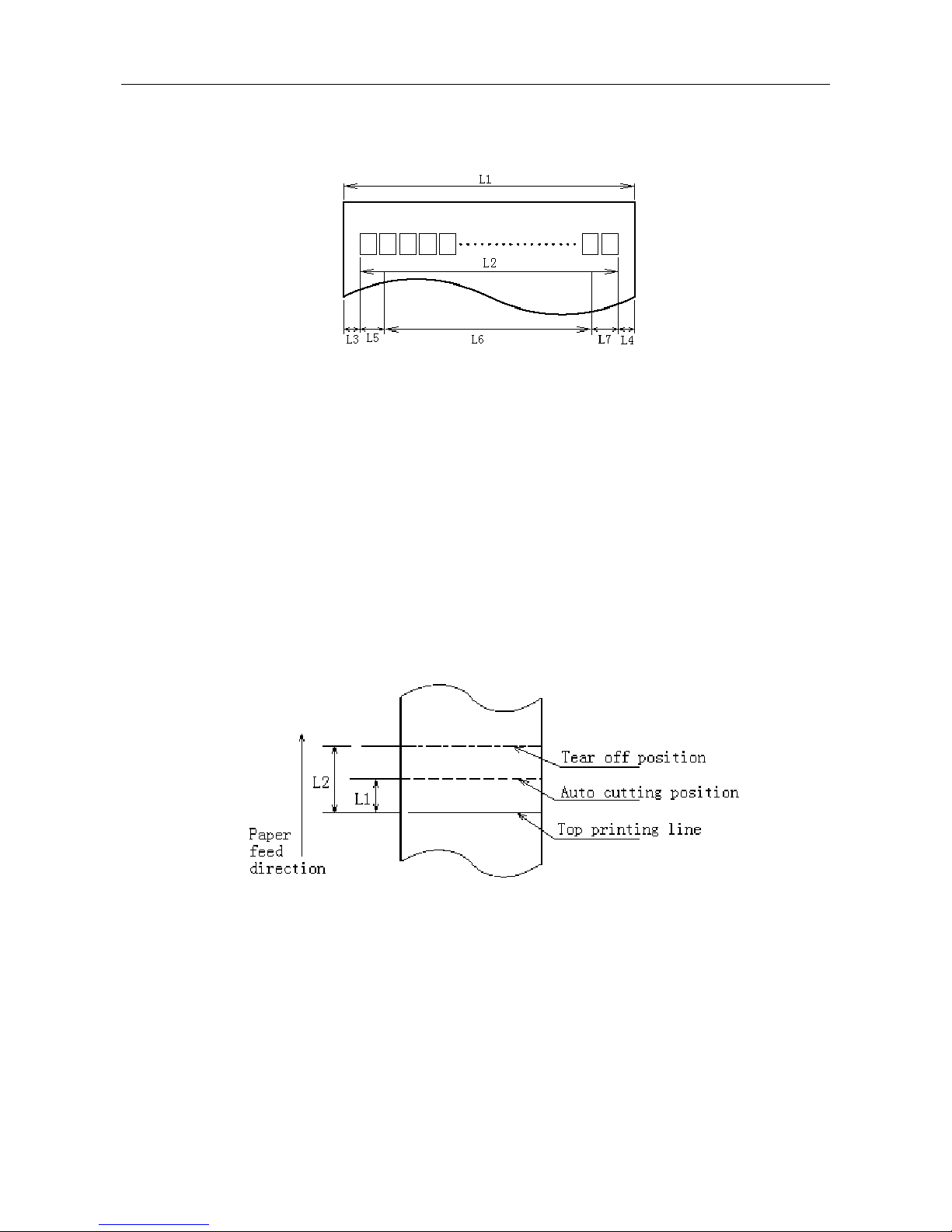
2.5.1 Printing Position
L1: Paper cabinet width 83.5mm
L2: Max Print width 80mm
L3: Space between the left end of print head and the left side of paper roll supply device (non-changeable)
1.75±0.3mm
L4: Space between the right end of print head and the right side of paper roll supply device (non-changeable)
1.75±0.3mm
L5: Left margin changeable, default is 7mm
L6: Print area width changeable, default is 64mm
L7: Right margin changeable, default is 9mm
2.5.2 Cutting Position
L1: Approximate: 16mm L2: Approximate: 34mm
- 6 -
BTP-2002NP User’s Manual
3 Outline and Parts
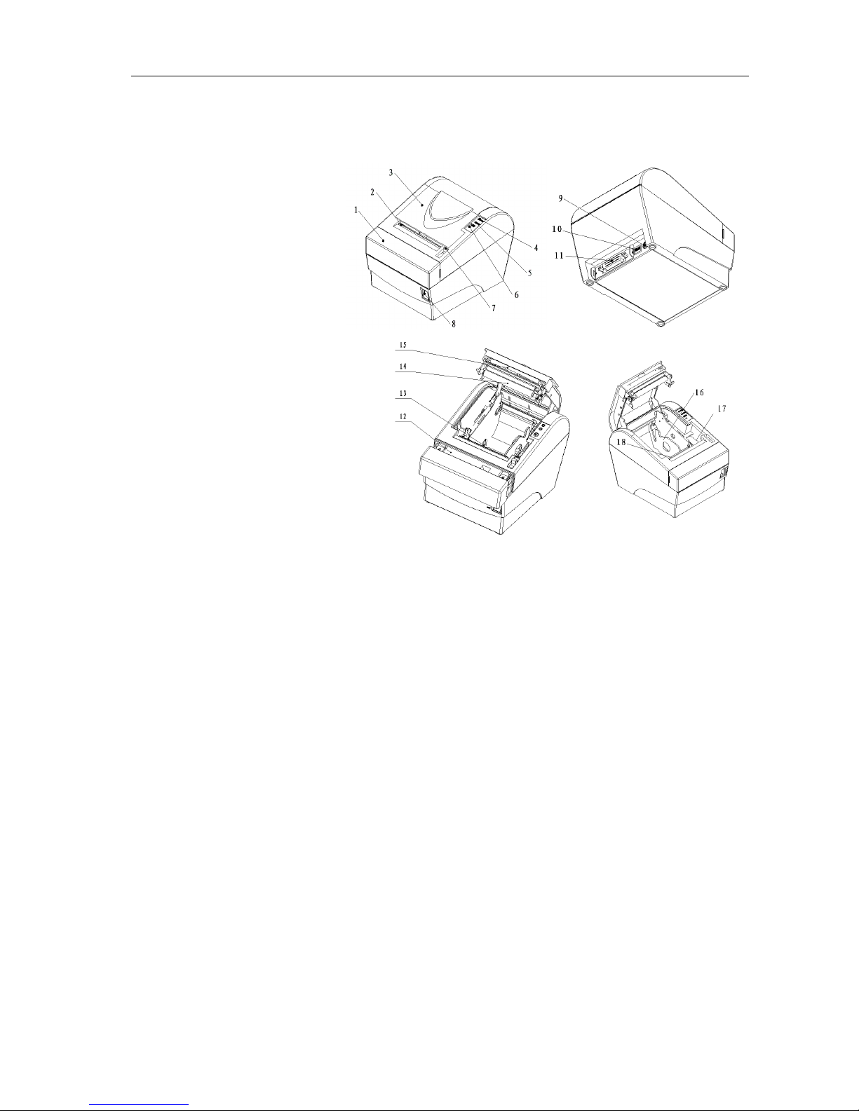
3.1 Outline and Parts
1—Cutter cover
2—Tear off bar
3—Printer top cover
4—Power LED
5—Error LED
6—Paper feed button
7—Top cover latch
8—Power switch
9—Power connector
10—Cash drawer connector
11—Signal Interface Connector
12—Sliding blade
13—Paper near end sensor
14—Printer platen
15—Stationary blade
16—Paper guide
17—Micro-switch
18—Paper end sensor
Functions of parts:
a- Paper feed button
¾Paper feeding function:
In normal status, press the FEED button shortly, the printer will feed paper by one line at a
time.
¾Paper testing and printing configuration information:
Holding on the feed button while turning on the printer, the self-test will start with printing the
configuration information; stop holding the button as soon as the printing starts.
Then the printer will print following indication information: “Press and Release FEED key to
print characters” and “Press and Hold FEED key to configure the printer”.
Press the FEED button for a short time, the printer will print a second page with a pattern
using the built-in character sets; Hold the FEED button for a long time, the printer will enter
button configuration mode.
b- Power LED
Indicate power status (ON/OFF).
- 7 -

BTP-2002NP User’s Manual
c- Error LED
Indicate all error status. Under normal conditions, ERROR LED is always off. under error
conditions, ERROR LED will flash.
d- Micro-switch
Detect the status of top cover.
e- Paper near end sensor
When the paper near the end, the error LED will flash. the printer will continue printing until the
paper end.
f- Paper end sensor
Paper end sensor is used to detect whether the paper roll has run out.
g- Power switch
Turn on/off the printer. “O” is to turn off the printer; “—” is to turn on the printer.
h- Paper guide
There are 4 long slots at the bottom of the paper cabinet. Putting the paper guide in a different
slot will allow the printer to use different paper widths listed as follows: 80±0.5 mm, 76±0.5
mm, 69.5±0.5 mm, 57.5±0.5 mm . Removing the paper guide will allow a paper width of
82.5 ±0.5mm.
Caution:
The Paper guide is an indispensable part of the printer and should be kept in the printer.
3.2 Error LED and Buzzer
The error LED and buzzer indicate the states of the printer, as described in the table below:
Errors Voice of buzzer LED flash
Cutter error (paper jam) Long-short-long Fast
Print head is raised up Short-long-short Slow
Print head is overheated (*) Long-short-long Fast
Paper near end No Faster
Paper end Short-short-short Faster
*The printer can detect the temperature of the print head with thermal resistor. If the
temperature of the print head has increased too much, the printer will decrease its print speed. If
the temperature becomes higher than 650 C, the protection circuit of the printer will force the
printer to stop printing; at the same time the light and sound signals as described in the table will
be given.
- 8 -
BTP-2002NP User’s Manual
4 Installation
4.1 Unpacking
Check whether all items listed on the packing list are present and in good condition. If any items are
damaged or missing, please contact your dealer or the manufacture for assistance.
4.2 Selecting the Installation Position and Direction
The BTP-2002NP can be installed in two positions: vertically on a wall or horizontally on a table. To
install the printer vertically on a wall, please obtain the optional wall mount system WMS-2002NP
from the supplier of the printer and follow instructions that are supplied with the system.
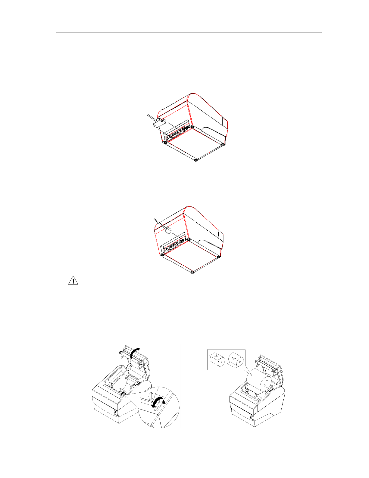
4.3 Grounding the Printer
Make sure the printer is connected to a ground line.
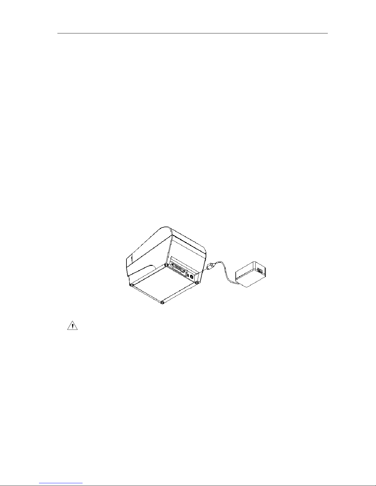
4.4 Connecting the Power Adapter
1) Ensure the printer power is turned off.
2) With the flat side of the power adapter’s cable connector facing upward, insert the cable
connector into the power connector on the backside of the printer.
3) Plug the power cord into a suitable wall outlet.
Caution:
Use only the manufacturers supplied power adapter or other equal model.
When connecting or disconnecting the cable connector of the power adapter, always hold
the connector but not the cable.
Do not pull on the power adapter cord, otherwise the cord may be damaged or broken,
causing a risk of fire or electric shock.
Do not place the Power adapter cord near a heating device; otherwise, the cover of the
cord may melt, causing a risk of fire or electric shock.
When the printer is not in use for a long period of time, disconnect the Power adapter from
the wall outlet for safety.
- 9 -
BTP-2002NP User’s Manual
4.5 Connecting Signal Cable
1) Ensure the printer power is turned off.
2) Put signal cable into suitable connector which should be fixed with plug screws or clip springs
(for USB connector, there are no such plug screws or clip springs).
3) Connect the other end of the signal cable to the host.
4.6 Connecting the Cash Drawer
1) Ensure the printer power is turned off.
2) Insert the cash drawer cable into the cash drawer kick-out connector on the back of the printer.
Caution:
Do not connect any other device than the specified drawer (Solenoid type) to the cash
drawer kick-out connector(Do not connect a telephone line either).
4.7 Inserting the Paper Roll
1) Open the top cover of printer.
2) Put the paper roll into the paper cabinet. See figure below.
- 10 -
BTP-2002NP User’s Manual
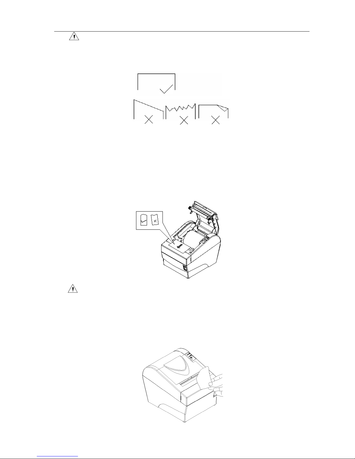
Caution:
Adjust the position of paper guide according to the width of the paper to be used.
Make sure that the beginning of roll paper is cut according to the requirement as
follows before loading:
Make sure that the heat sensitive side of paper faces the print head and the rolling
direction of paper meets the requirements.
The paper should be neatly fitted on the paper roll when loading.
The paper roll should be able to freely roll in the paper cabinet of the printer and not be
stuck as it may cause paper jam or other malfunctions.
3) Pull the beginning of the roll paper out up to the end of the upper cover, then close the
printer cover, as follows:
Caution:
Both sides of the printer cover must be pressed down completely in order to ensure
that the top cover is closed completely.
The paper should leave the paper exit straight and not crumpled as shown in the above
figure.
4) Tear off the surplus portion of paper with the tear off bar.
- 11 -
BTP-2002NP User’s Manual
4.8 Self-test
The self-test lets you know if the printer is operating properly. It checks the control circuits, printer
mechanisms, print quality, firmware version and prints out the settings.
The test is independent of any other equipment or software and can be started as follows:
1) Ensure the printer power is turned off and the top cover is closed properly.
2) Holding on the feed button while turning on the printer, the self-test will start with printing the
configuration information; stop holding the button as soon as the printing starts.
3) Then the printer will print following indication information: “Press and Release FEED key to
print characters” and “Press and Hold FEED key to configure the printer”.
4) Press the FEED button for a short time, the printer will print a second page with a pattern
using the built-in character sets; Hold the FEED button for a long time, the printer will enter
button configuration mode.
5) The printer ends and cuts the self-test page automatically.
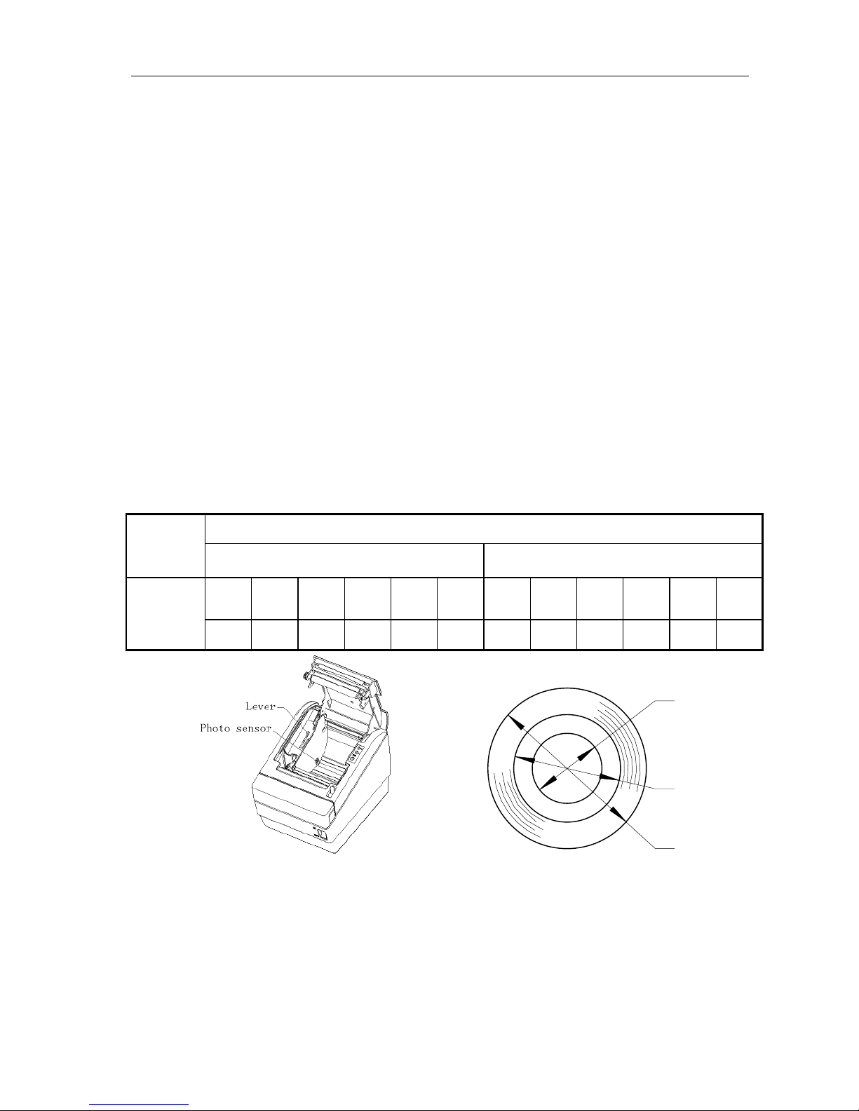
4.9 Adjusting the Paper Near End Sensor
The remaining detectable amount of paper on the paper roll varies with the inside and outside
diameters of the paper roll core. The minimum detectable amount of paper on the paper roll can be
set by the following method:
For paper rolls with a core inside diameter (A) of 14mm and a core outside diameter (B) of 22 mm
Paper
thick-ness
(mm) Detected approx. diameter (C) in mm Approx. remaining paper length
Level
1
Level
2
Level
3
Level
4
Level
5
Level
6
Level
1
Level
2
Level
3
Level
4
Level
5
Level
6
0.06
φ26 φ28 φ30 φ32 φ34 φ36 2.5m 3.8m 5.1m 6.5m 8.0m 9.7m
A
B
C
Figure 1 Changing the paper-near-end position
Note:
The factory setting of the paper near end sensor is level 2.
The value of C and the remaining paper length are calculated values. There may be small
deviations due to variations of the printer mechanics and the paper near end sensor.
If the paper roll has a core of dimensions different from that in above table, the value of C
and the remaining paper length may have different values.
- 12 -

BTP-2002NP User’s Manual
5 Routine maintenance
5.1 Cleaning the Print head
When one or more of the following phenomena occur, the Print head need to be cleaned.
¾Printout is light.
¾Some of vertical columns on printout are light.
¾The paper feeds with loud noises.
To clean the Print head, follow the steps given below:
¾Turn off the printer and open the top cover.
¾It may take a few minutes for print head to cool down if it has just finished printing.
¾Wipe off stain, such as dust, on the heating element of Print head with an alcohol cotton.
¾Close printer top cover when the alcohol has evaporated completely.
5.2 Cleaning the Sensor
When one or more of the following phenomena occur, please clean the paper end sensor.
¾During printing, the printer stops printing occasionally and indicates incorrectly that the
printer is out of paper.
¾Doesn’t alarm paper end when paper is end indeed.
To clean the paper end sensor, follow the steps given below:
¾Turn off the printer and open the top cover.
¾Wipe off stain and dust on the surface of the sensor with an alcohol cotton carefully.
¾Close printer cover when the alcohol has evaporated completely.
5.3 Cleaning the Platen Roller
When one or more of the following phenomena occur, please clean the platen roller.
¾Printout is light.
¾Some vertical columns on printout are not clear.
¾Paper feeds with loud noises.
To clean the platen roller, follow the steps given below:
¾Turn off the printer and open the top cover.
¾Wipe off stain, such as dust and the like, on the platen roller by using an alcohol cotton.
¾Close the top cover when the alcohol has evaporated completely.
Caution:
Before starting routine maintenance, make sure that the printer has been switched off.
Do not touch the surface of print head with your hands or any metallic objects. Do not use
any other method to clean the print head, platen roller and sensors than described in this
manual.
Do not use an organic solvent like gasoline, and acetone.
After cleaning of the paper end sensor, it is recommended to check the printer settings.
It may take a few minutes for the alcohol to evaporate before printing.
- 13 -

BTP-2002NP User’s Manual
6 Interface Signal
6.1 Parallel Interface
The parallel interface is bi-directional which supports BUSY/ACK handshaking protocol. Its connector
is 36pin centronics.
Pin No. Source Compatible Mode Pin No. Source Compatible Mode
1 H Strobe 19 Signal Ground
2 H Data 0 (Least Significant Bit) 20 Signal Ground
3 H Data 1 21 Signal Ground
4 H Data 2 22 Signal Ground
5 H Data 3 23 Signal Ground
6 H Data 4 24 Signal Ground
7 H Data 5 25 Signal Ground
8 H Data 6 26 Signal Ground
9 H Data 7 (Most Significant Bit) 27 Signal Ground
10 P Ack 28 Signal Ground
11 P Busy 29 Signal Ground
12 P P Error 30 Signal Ground
13 P Select 31 H nlnit
14 Not defined 32 P -nFault
15 Not defined 33 Signal Ground
16 Logic Ground 34 Not defined
17 Chassis Ground 35 Not defined
18 P Peripheral Logic High 36 H nSelectIn
36 PIN CENTRONICS connector
6.2 Serial Interface
The serial interface is RS-232 compatible and its connector is 25pin female D type.
PIN No. Signal
PIN1 Frame Ground
PIN2 TXD
PIN 3 RXD
PIN 4 RTS
PIN 5~6 NC
PIN 7 Signal Ground
PIN 8~19 NC
PIN 20 DTR
PIN 21~25 NC
The 25 PIN D-SUB connector
- 14 -

BTP-2002NP User’s Manual
- 15 -
User may check the current setting status of the interface by printing a configuration table. The
default setting is as follows:
Baud rate: 9600bps
Data bit: 8
Parity bit: None
Stop bit: 1
Handshaking: Hardware
Serial interface connection example:
Host Printer
FG-----------------FG
TXD---------------RXD
RXD--------------TXD
CTS---------------RTS
DSR--------------DTR
DTR--------------DSR
SG ----------------SG
6.3 RS-485 Serial Interface
Signal definition and functions for DB25 connector are shown as below:
Pin
No.
Signal
Name
Signal
Direction Functions
1 FG - Frame Ground
2
3
SD1
SD2 Output Send data
4
5
RD1
RD2 Input Receive data
7 SG - Signal Ground
8
9
DR1
DR2 Output
When selecting DTR/DSR, the signal is used to indicate the printer status.
1) DR1>DR2 means that the printer is ready to receive data;
DR1<DR2 means that the printer is busy.
2) When selecting XON/XOFF, this signal indicates if the printer is connected
and ready to receive data properly. SPACE means the printer is ready to
receive data. If the signal is always DR1>DR2, it means the printer is ready
to receive data. Except the cases as below, the signal is always DR1>DR2:
·From power-on to printer ready for data reception;
·When the printer is tested itself.
10
11
CS1
CS2 Input
The signal indicates if the host can receive data. CS1>CS2 means that the
host can receive data; CS1<CS2 means that the host can’t receive data.
When selecting DTR/DSR, the printer shall transmit data after confirming it.
(Except the data transmitted via DLE EOT and GS a)
When selecting XON/XOFF, the printer doesn’t check this signal.
Other manuals for BTP-2002NP
1
Table of contents
Other Shandong Printer manuals

Shandong
Shandong BT-T080R Owner's manual

Shandong
Shandong BTP-R880NP User manual

Shandong
Shandong BTP-M280 User manual

Shandong
Shandong U80II User manual

Shandong
Shandong BTR-R980 User manual

Shandong
Shandong BK-T680 User manual

Shandong
Shandong BTP-2002NP Owner's manual

Shandong
Shandong BT-T080 plus Owner's manual

Shandong
Shandong BTP-R580 User manual


