Shandong BTP-M280 User manual

SERVICE MANUAL
Impact Receipt Printer
BTP-M280
Shandong New Beiyang Information Technology Co., Ltd.
CONFIDENTIAL

Confidential BTP-M280 Service Manual
- 1 -
Revision Sheet
Date Version No. Description Distributor
2007-05-16 V1.0 Release
Mr. zheng lei
Mr. zhao zhenxing
Mr. Yao Xingmao
Mr. Yu zhuanlong
2008-2-20 V1.01 Adjust the format of 1.2 Mr. Yu zhuanlong

Confidential BTP-M280 Service Manual
- 2 -
Declaration
Information in this document is subject to change without notice. SHANDONG NEW BEIYANG
INFORMATION TECHNOLOGY CO., LTD. (hereinafter referred to as “SNBC”) reserves the right to
improve product as new technology, components, software, and firmware become available. If users need
further data about this products or have any doubt about safety issues that might arise from using it, please
feel free to contact SNBC or your local agents.
No part of this document may be reproduced or transmitted in any form or by any means, electronic or
mechanical, for any purpose without the express written permission of SNBC.
Copyright
Copyright © 2007 by SNBC
Printed in China
Version 1.01
Trademark
SNBC registered trademarks:
Warning and Caution
Warning: Items shall be strictly followed to avoid damages to body and equipment.
Caution: Items with important information and prompts for operating the printer.
The quality control system of SNBC has been approved of the following certification.
(DNV)ISO9001:2000
The environmental control system of SNBC has been approved of the following certification.
(DNV)ISO14001:2004

Confidential BTP-M280 Service Manual
- 3 -
Notes
1) Use this manual to troubleshoot printer faults.
2) Do not plug or pull out the signal cable, change print head or do maintenance to the printer when the
printer and the computer are powered on.
3) Please take anti-static application when you maintain print head and other electronics component.
4) After turning off the printer, you should wait for at least 20 seconds if you want to turn on the printer
again.
5) Do not print without paper and ribbon; otherwise you may damage the print head iron mat and print
head.

Confidential BTP-M280 Service Manual
- 4 -
Contents
1 FEATURES AND SPECIFICATIONS........................................................................................................1
1.1 FEATURES............................................................................................................................................1
1.2 TECHNICAL SPECIFICATIONS..................................................................................................................2
2 PRINTER OVERVIEW ..............................................................................................................................3
2.1 MAIN CONTROL BOARD UNIT BLOCK DIAGRAM.......................................................................................3
3 MAIN CONTROL BOARD DESCRIPTION...............................................................................................5
3.1 USB INTERFACE...................................................................................................................................5
3.1.1 Parameter ...................................................................................................................................5
3.1.2 Interface signal............................................................................................................................5
3.1.3 USB interface connection............................................................................................................5
3.2 SERIAL INTERFACE ...............................................................................................................................5
3.2.1 Parameter ...................................................................................................................................5
3.2.2 Interface connection and signal function.....................................................................................6
3.2.3 Serial connection.........................................................................................................................6
3.3 PARALLEL INTERFACE ...........................................................................................................................6
3.3.1 Parameter ...................................................................................................................................6
3.3.2 Time Sequence of the Parallel Interface Module.........................................................................6
3.3.3 Pin assignment............................................................................................................................7
3.3.4 Parameter ...................................................................................................................................8
3.3.5 Effect of printer’s status on parallel interface...............................................................................8
3.4 ETHERNET INTERFACE ..........................................................................................................................8
3.4.1 Interface character ......................................................................................................................8
3.4.2 Protocol supported......................................................................................................................9
3.4.3 Electrical character......................................................................................................................9
3.4.4 Frame type..................................................................................................................................9
3.4.5 Pin assignment............................................................................................................................9
3.5 WLAN INTERFACE................................................................................................................................9
3.5.1 Interface character ......................................................................................................................9

Confidential BTP-M280 Service Manual
- 5 -
3.5.2 Protocol supported....................................................................................................................10
3.5.3 Electrical character....................................................................................................................10
4 DISASSEMBLY AND ASSEMBLY..........................................................................................................11
4.1 MAINTENANCE TOOLS.........................................................................................................................11
4.2 DISASSEMBLE THE PRINTER ................................................................................................................12
4.2.1 Disassemble the Cover of Printer..............................................................................................12
4.2.2 Disassemble the Main Control Board Cover .............................................................................14
4.2.3 Disassemble the Stationary Blade Cutter Module.....................................................................15
4.2.4 Disassemble the Platen Roller Module (Without Rewinder)......................................................16
4.2.5 Disassemble the Paper Cabinet Module...................................................................................18
4.2.6 Disassemble the Print Module...................................................................................................22
5 PRINTER MAINTENANCE.....................................................................................................................26
5.1 MAIN PART REPLACING........................................................................................................................26
5.1.1 Print head replacing................................................................................................................26
5.1.2 Cutter replacing ......................................................................................................................27
5.1.3 Main control board replacing ..................................................................................................28
5.1.4 Paper feed motor replacing ....................................................................................................29
5.1.5 CR motor replacing.................................................................................................................29
5.1.6 Upper mark sensor replacing..................................................................................................30
5.1.7 Lower mark sensor replacing..................................................................................................31
5.1.8 HP sensor replacing ...............................................................................................................32
5.1.9 Paper sensor replacing...........................................................................................................32
5.2 PRINTER ADJUSTMENT ........................................................................................................................33
5.2.1 Print distance adjustment..........................................................................................................33
5.2.2 Tight denti-form belt of carriage ................................................................................................33
6 ERROR TYPES AND PROCESSING.....................................................................................................34
7 TROUBLESHOOTING............................................................................................................................35
7.1 PRINT EFFECT ABNORMAL ...................................................................................................................35
7.2 PAPER DETECTION ABNORMAL .............................................................................................................35

Confidential BTP-M280 Service Manual
- 6 -
7.3 PRINTING WITH NOISE .........................................................................................................................35
7.4 RIBBON ACTION ABNORMAL .................................................................................................................36
7.5 CUTTER ACTION ABNORMAL.................................................................................................................36
7.6 PRINTER DOESN’T WORK.....................................................................................................................37
7.7 PROBLEM DURING THE PRINTING PROCESS ..........................................................................................37
APPENDIX.................................................................................................................................................38
APPENDIX 1HEXADECIMAL DUMP MODE ...................................................................................................38
APPENDIX 2COMMAND LIST......................................................................................................................39
APPENDIX 3EEPROM SETTING TABLE ......................................................................................................41
APPENDIX 4SPARE PART LIST ...................................................................................................................42
APPENDIX 5EXPLODED DRAWING OF THE PRINTER.....................................................................................45
APPENDIX 6PART LIST..............................................................................................................................48
APPENDIX 7OUTLINE DRAWING.................................................................................................................51
APPENDIX 8MAIN BOARD LAYOUT .............................................................................................................52
APPENDIX 9LUBRICATION.........................................................................................................................53

Confidential BTP-M280 Service Manual
- 1 -
1 Features and Specifications
1.1 Features
The BTP-M280 is a 9 pin serial dot matrix receipt impact printer. Features include such as good print
quality, high speed printing and stable performance. It is widely used for receipt applications such for POS,
Kitchen and Finance terminal.
The BTP-M280 can be connected to host computers via a Serial interface, Parallel interface, USB interface,
Ethernet interface, WLAN interface. USB is the standard interface and other interfaces are optional.
The BTP-M280 offers drivers and applications under WINDOWS 98/NT4.0 /2000/2003/XP/Vista.

Confidential BTP-M280 Service Manual
- 2 -
1.2 Technical Specifications
Item Specification
Print mode 9-pin serial impact dot matrix
Print speed Max. 4.7LPS (400 dots/line)
Print width Max. 400(half dots)/200(full dots)
Paper type Continuous paper or marked paper
Single layer Paper width: 80±0.5mm, 76±0.5mm, 69.5±0.5mm, 57.5±0.5mm;
Paper thickness: 0.06—0.085mm
Paper
Multi-layer paper
(1 original+1 copies)
Paper width: 80±0.5mm, 76±0.5mm, 69.5±0.5mm, 57.5±0.5mm;
Paper thickness: 0.05—0.08mm, total thickness≤0.14 mm
Character type Font A: 9×9 Font B: 7×9 Chinese: 16×16
80/76mm 69.5mm 57.5mm
Font A 33 CPL 30 CPL 25 CPL
Font B 40 CPL 36 CPL 30 CPL
Characters/line (Default)
Chinese 22 CPL 20 CPL 16 CPL
Character size (Default) Font A: 1.6×3.1mm Font B: 1.2×3.1mm Chinese: 2.7×2.9mm
Character
Characters/inch (Default) Font A: 13.3CPI Font B: 16CPI Chinese: 8.9CPI
Receive buffer 8KB
NV bit image data area 128KB
Data
buffer
User NV memory 8KB
Ribbon specification ERC-38 ribbon cartridge
ERC-38(P) 4,000,000 characters
ERC-38(B) 3,000,000 characters
Ribbon lifetime
ERC-38(B/R) Black: 1,500,000 characters
Red: 750,000 characters
Communication interface USB (Fixed) + IEEE1284/RS-232/Ethernet / Wi-Fi interface (optional)
Cash drawer connector 1~2 cash drawers
Power supply DC 24V±5% average current 1.5 A
Printing Mechanism lifetime 10,000,000 lines
Print head lifetime 150,000,000 characters
Reliability
Cutter 1,500,000 times(partial cut, paper thickness:0.07mm)
1,000,000 times(full cut , paper thickness:0.07mm)
Operating temperature and humidity 5~45℃,20~90%RH (40 )℃
Storage temperature and humidity -40~60℃,20%~93%RH (40 )℃
Dimensions 160mm(W)×245mm(D)×145mm(H)
Weight 2.9kg
Confidential BTP-M280 Service Manual
- 3 -
2 Printer Overview
The BTP-M280 printer consisits of the following parts:
Pinter mechanism part, NDLF main control board, extended interface board.
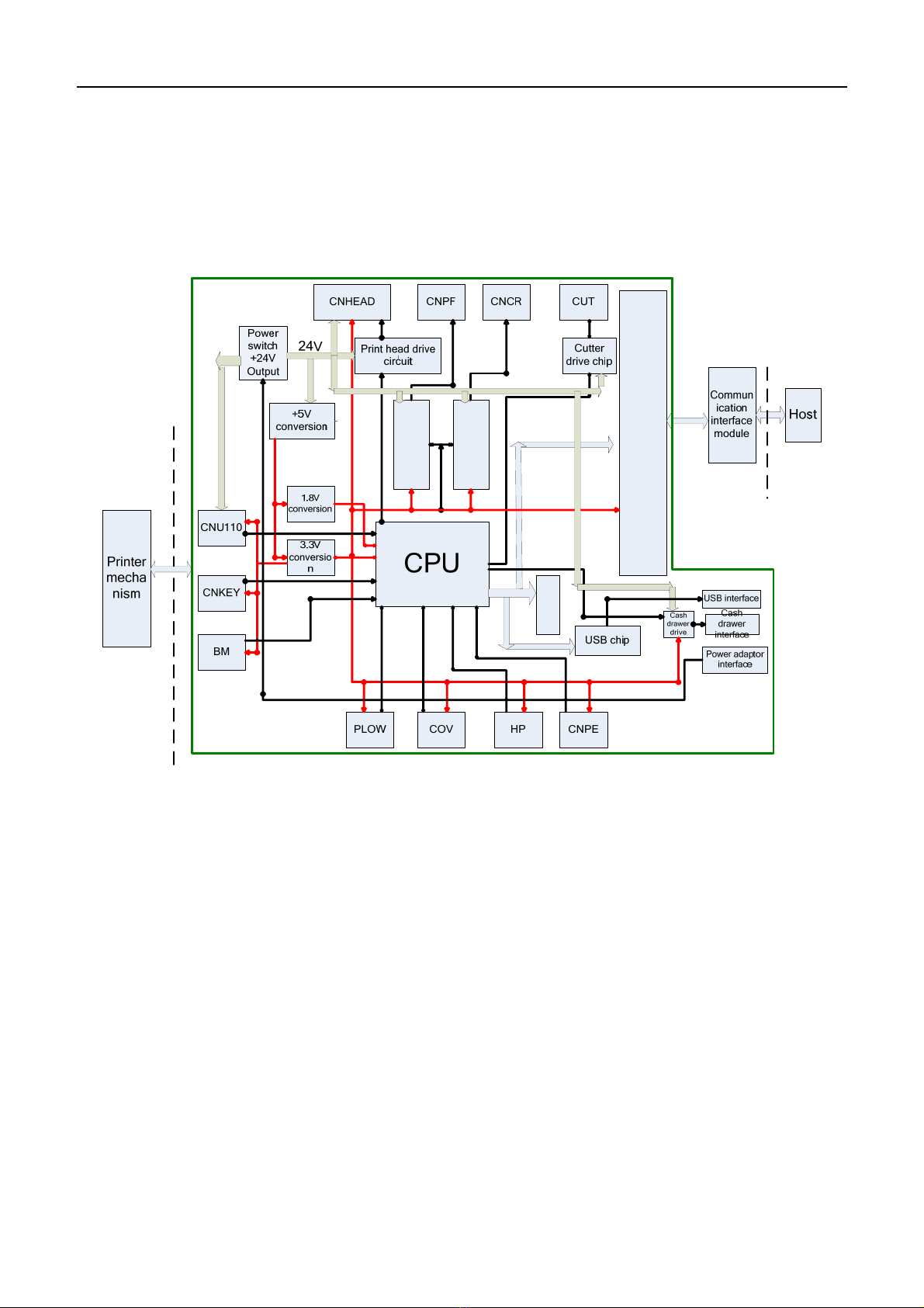
2.1 Main Control Board Unit Block Diagram
Main control board unit block diagram is shown as below:
FLASH
Paper feed motor
drive chip
Carriage motor
drive chip
Communication interface
connector
3.3V
1.8V
Motor drive signal
Print head drive signal
5V
Main Control Board Unit Block Diagram
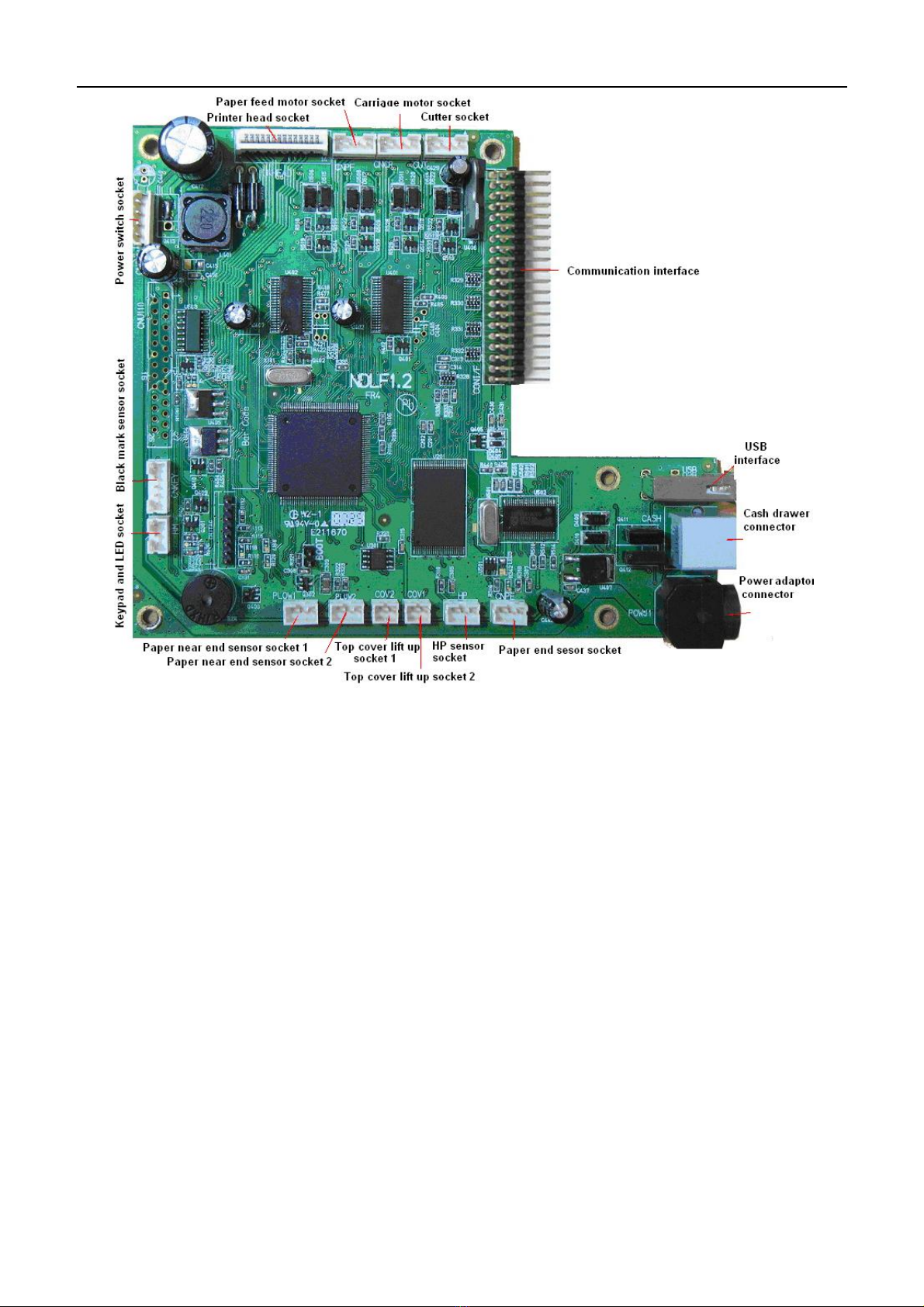
Confidential BTP-M280 Service Manual
- 4 -
Position of all the sockets in the main control board
Confidential BTP-M280 Service Manual
- 5 -
3 Main Control Board Description
BTP-M280 can be connected to another device with USB, serial, parallel, Ethernet or WIFI interface. The
USB interface is fixed and other is optional.
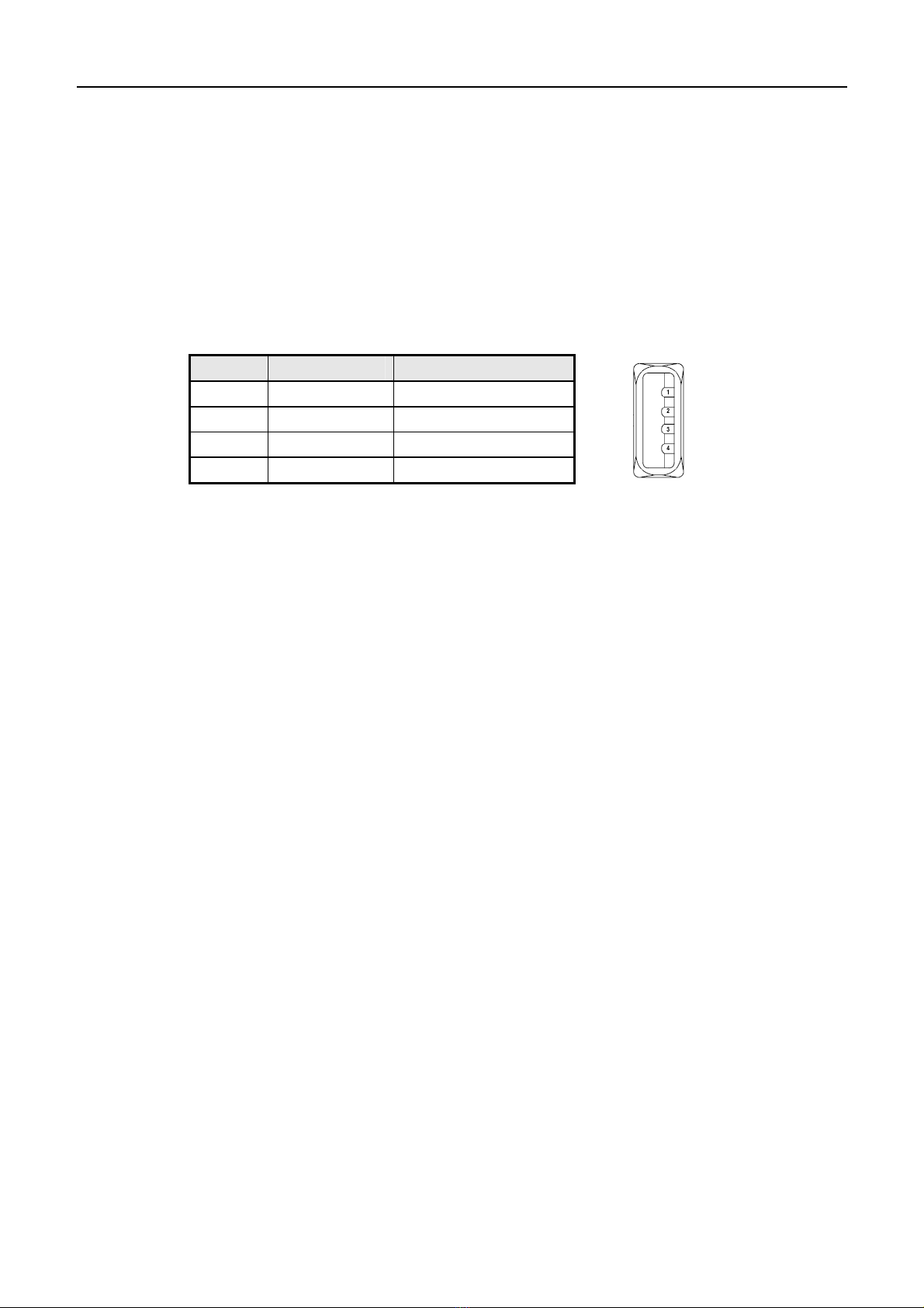
3.1 USB interface
3.1.1 Parameter
¾Data transfer:Supports USB1.1 Protocol
¾Socket:USB A type standard socket
3.1.2 Interface signal
3.1.3 USB interface connection
Host Printer
VBUS..................................…VBUS
DATA- ................................…DATA-
DATA+................................... DATA+
GND .......................................GND
3.2 Serial interface
3.2.1 Parameter
¾Data transmission:Asynchronous serial communicate
¾Handshaking:DTR/DSR or XON/XOFF
¾Voltage:MARK=-3to-15V:Logic "1"/ OFF
¾SPACE = +3 to +15V:Logic "0"/ ON
¾Baud rate:1200, 2400, 4800, 9600, 19200, 38400, 57600 bps
¾[bps: bits per second]
¾Data bit:7 bit or 8 bit
¾Parity bits:No
¾Stop bit:1 bit or 2 bit
¾Socket:D-SUB 25PIN hole socket
Notice:
Handshaking, baud rate, data bit and stop bit can be set by EEPROM and feed button.
Pin Signal Function
1 VBUS +5V
2 DATA- Data-
3 DATA+ Data+
4 GND Ground
Confidential BTP-M280 Service Manual
- 6 -
3.2.2 Interface connection and signal function
Signal and function:
Pin Signal Name Signal Direction Function
1 FG — Frame ground
2 TXD OUTPUT Data output
3 RXD INPUT Data input
4 RTS OUTPUT Ask for sending
6 DSR INPUT Host ready
7 SG — Signal ready
20 DTR OUTPUT Data terminal ready
3.2.3 Serial connection
Host Printer
TXD---------------RXD
RXD---------------TXD
DSR---------------DTR
CTS---------------RTS
RTS---------------CTS
DTR---------------DSR
FG -----------------FG
SG -----------------SG
3.3 Parallel interface
Parallel interface works under IEEE1284 compatible mode and bi-direction mode.
3.3.1 Parameter
¾Data transmission:8 bit parallel
¾Synchronized mode:Externally supplied nStrobe signals
¾Handshaking mode:Busy Signal
¾Handshaking pressure:TTL compatible
¾Connector:IEEE 1284-B(CENTRONICS) socket
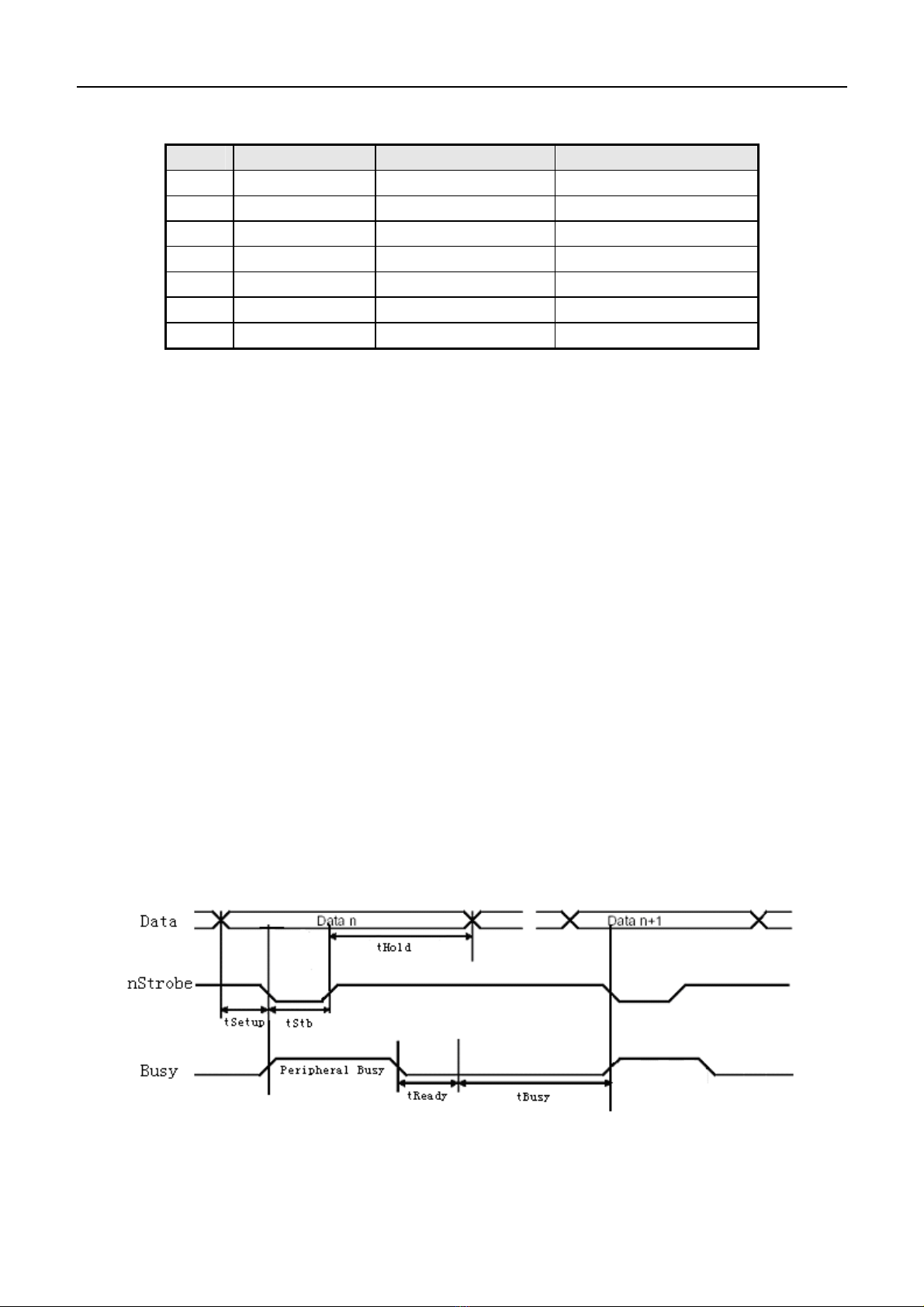
3.3.2 Time Sequence of the Parallel Interface Module
Time Sequence of Parallel Interface(Compatible mode)

Confidential BTP-M280 Service Manual
- 7 -
Signal Min. Max.
tSetup 750 -
tReady 0 -
tStb 750 -
tBusy 0 500
tHold 750 -
Time Request of Parallel Interface
3.3.3 Pin assignment
Pin Signal source Signal definition Pin Signal source Signal definition
1 H nStrobe 19 Signal Ground
2 H Data 0 (Least Significant Bit) 20 Signal Ground
3 H Data 1 21 Signal Ground
4 H Data 2 22 Signal Ground
5 H Data 3 23 Signal Ground
6 H Data 4 24 Signal Ground
7 H Data 5 25 Signal Ground
8 H Data 6 26 Signal Ground
9 H Data 7 (Most Significant Bit) 27 Signal Ground
10 P Ack 28 Signal Ground
11 P Busy 29 Signal Ground
12 P PError 30 Signal Ground
13 P Select 31 H nInit
14 H nAutoLF 32 P nFault
15 Not defined 33 Signal Ground
16 Logic Gnd 34 Not defined
17 Chassis Gnd 35 Not defined
18 P Peripheral Logic High 36 H nSelectIn
Parallel Interface Pin Assignment
Notice:
H stands for host end, P stands for printer end.
Parallel interface signal adopting TTL pressure. Please make sure that both ascending and
descending time of the host end are less than 0.5μs when using the printer to print.
When data transmitting, the host end should not neglect the Busy signal, otherwise the
printing data will be lost.
The parallel interface signal cable should be as short as possible.
Confidential BTP-M280 Service Manual
- 8 -
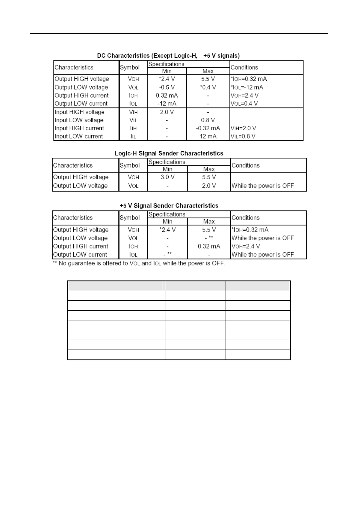
3.3.4 Parameter
3.3.5 Effect of printer’s status on parallel interface
Status /nFault PE
Normal status High Low
Paper end Low High
Rear cover open Low Low
Cutter error Low Low
Input voltage abnormal Low Low
Print head overheated Low Low
HP error Low Low
Notice:
When the above error occurs, user can inquire the printer’s status from the Pin of parallel.
3.4 Ethernet interface
3.4.1 Interface character
¾Support 10BASE-T communicate
¾Ethernet II frame type compatible
¾LED indicates the net connection status and data transmission status
¾Support 9100 port printing
¾Support auto status back

Confidential BTP-M280 Service Manual
- 9 -
¾Support parameter configuration
¾Support firmware update online
¾Support printer status inquire and interface module maintenance based in HTTP mode
3.4.2 Protocol supported
¾IP
¾ARP
¾ICMP
¾TCP
¾UDP
¾DHCP
¾TFTP
¾HTTP
3.4.3 Electrical character
Output signal:
¾Available differential mode voltage is bigger than 450Mv and peak voltage is no more than
13V.
¾Peak voltage of common mode voltage is no more than 2.5V.
Input signal:
The signal is effective only when the differential mode voltage is bigger than 160mv.
3.4.4 Frame type
Ethernet II frame type compatible.
3.4.5 Pin assignment
The interface use 10BASE-T standard which comply to IEEE802.3.
Pin Signal Name Description
1 TX+ Data sending +
2 TX- Data sending-
3 RX+ Data receiving+
4 NC Reserved
5 NC Reserved
6 RX- Data receiving-
7 NC Reserved
8 NC Reserved
3.5 WLAN Interface
3.5.1 Interface character
¾Support 802.11b/g protocol
¾Support 9100 port printing and LPR printing
¾Support auto status back
¾Easy configuration
¾Firmware update online
¾Support HTTP function

Confidential BTP-M280 Service Manual
- 10 -
3.5.2 Protocol supported
¾IP
¾ARP
¾ICMP
¾TCP
¾UDP
¾DHCP
¾TFTP
¾HTTP
3.5.3 Electrical character
Comply to 802.11b/g protocol.

Confidential BTP-M280 Service Manual
- 11 -
4 Disassembly and Assembly
Cautions:
1) Do not disassemble, assemble or adjust the printer if it works properly. Do not loosen any
screw unless necessary.
2) When disassembling and assembling, avoid damaging all wires and cables. Do not place them
in a narrow space or improper position.
3) When handling the print head or electronic component, make sure to take some measures to
protect it from electrostatic charge.
4) During maintenance, be careful not to leave parts or screws loose inside the printer.
5) During maintenance, be careful not to damage the print head surface and the HP iron mat.
4.1 Maintenance Tools
Maintenance Tools:
¾Screw Driver (Cross-shaped type)
¾Sharp-nose pliers
¾Wire clamp pliers
Assistant materials:
¾Lubricant
¾Alcohol
¾Absorbent cotton
Confidential BTP-M280 Service Manual
- 12 -
4.2 Disassemble the Printer
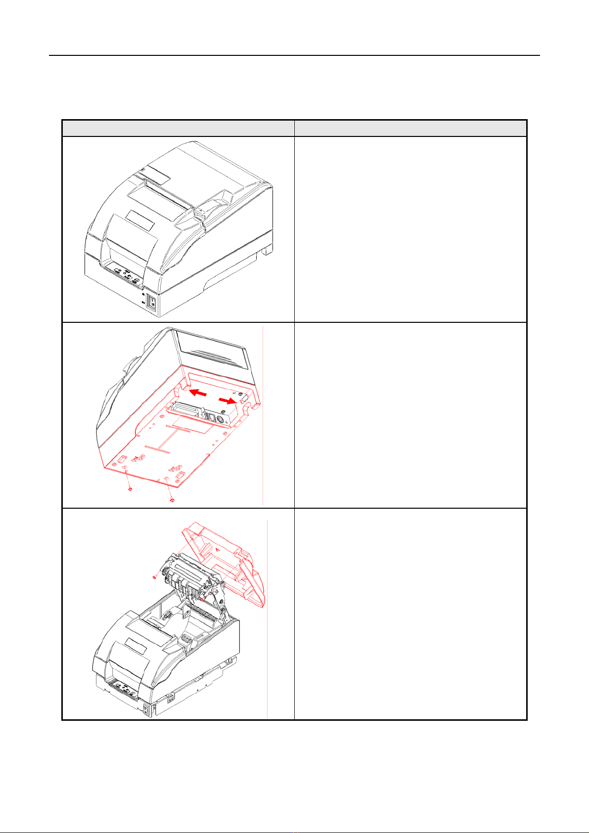
4.2.1 Disassemble the Cover of Printer
Pictures Instructions
Top view of printer.
1) Unscrew the two screws (M3x7) as shown with the
screw driver;
2) Push the lock frame of lower cover with a moderate
force as the arrow shown in the figure and take it
off.
Note:
Please use a moderate force to avoid damage to the
lower cover when disassembling the lock frame.
1) Unscrew the two screws (2.9x8) as shown with the
screw driver;
2) Push the lock frame of upper cover with a
moderate force as shown and take it off.
Note:
Please use a moderate force to avoid damage to the
upper cover when disassembling the upper cover.
Confidential BTP-M280 Service Manual
- 13 -
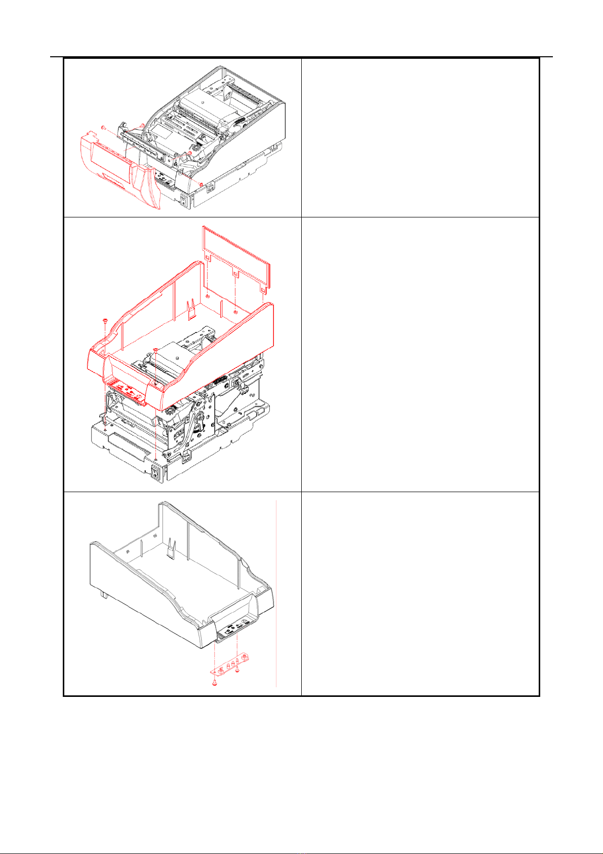
Unscrew the four screws (Four ST2.9x6) as shown with
the screw driver and take the front cover off.
Note:
Please use a moderate force to avoid damage to the font
cover when disassembling the front cover.
1) Unscrew the two screws (M3x7) as shown with the
screw driver;
2) Unplug the connection wire of Feed button and
that of main control board;
3) Push the lock frame of middle cover with a
moderate force as shown and take it off;
4) Take the middle cover holder off with a moderate
force.
Note:
Please use a moderate force to avoid damage to
the middle cover when disassembling the lock
switch;
Please do not pull the connection wire to avoid
damage to the wire when pluging and unplugging
the connection wire.
Unscrew the two screws (ST2.9x6) as shown with the
screw driver and take the Feed button board off.
Table of contents
Other Shandong Printer manuals

Shandong
Shandong U80II User manual

Shandong
Shandong BK-T680 User manual

Shandong
Shandong BTP-R880NP User manual

Shandong
Shandong BT-T080 plus Owner's manual

Shandong
Shandong BT-T080R Owner's manual

Shandong
Shandong BTR-R980 User manual

Shandong
Shandong BTP-2002NP User manual

Shandong
Shandong BTP-2002NP Owner's manual

Shandong
Shandong BTP-R580 User manual


