Shandong BK-T680 User manual

USER’S MANUAL
Embedded Printer
BK-T680
Shandong New Beiyang Information Technology Co., Ltd.

BK-T680 User’s Manual
- 1 -
Declaration
Information in this document is subject to change without notice. SHANDONG NEW BEIYANG
INFORMATION TECHNOLOGY CO., LTD. (hereinafter referred to as “SNBC”) reserves the right to
improve products as new technology, components, software, and hardware become available. If users
need further data about these products, please feel free to contact SNBC or your local dealer.
No part of this document may be reproduced or transmitted in any form or by any means for any purpose
without the express written permission of SNBC.
Copyright
Copyright © 2013 by SNBC
Printed in China
Version 1.1
Trademark
Registered trademark of SNBC:
Warning and caution
Warning: Items shall be strictly followed to avoid injury or damage to body and equipment.
Caution: Items with important information and prompts for operating the printer.
Caution: Thermal elements. No touching.
Warning: Do not touch equipment to avoid damaging it for static electricity.
SNBC has been approved by the following certifications:
ISO9001 Quality Control System Certification
ISO14001 Environmental Management System Certification
OHSAS18001 Occupational Health and Safety Management System Certification
IECQ QC080000 Hazardous Substance Process Management System Certification
Contact us
Address: No.169 huoju road, high-tech zone, Weihai, China
Hot line: 400-618-1368、800-860-1368
Fax: +86-631-5656098
PC: 264209
Website: www.newbeiyang.com.cn

BK-T680 User’s Manual
- 2 -
Safety instructions
Before installing and using the printer, please read the following items carefully:
1) Install the printer on a flat and stable surface;
2) Reserve adequate space around the printer so that convenient operation and maintenance can be
performed;
3) Keep the printer far away from water source, and do not expose the printer to direct sunlight, strong
light and heat;
4) Do not use or store the printer in a place exposed to high temperature, high humidity or serious
pollution;
5) Do not place the printer in a place exposed to vibration or impact;
6) No condensation is allowed to the printer. In case of such condensation, do not turn on the power
until it has completely gone away;
7) Connect the printer power to an appropriate grounding outlet. Avoid sharing one electrical outlet with
large power motors or other devices that may cause the fluctuation of voltage;
8) Disconnect the power when the printer is deemed to idle for a long time;
9) Don’t spill water or other electric materials into the printer (e.g. metal). In case this happens, turn off
the power immediately;
10) Do not allow the printer to start printing when there is no recording paper installed; otherwise the
print head and platen roller will be damaged;
11) To ensure quality print and normal lifetime, use recommended paper or its equivalent;
12) Shut down the printer when connecting or disconnecting interfaces to avoid damages to control
board;
13) Set the print darkness to a lower grade as long as the print quality is acceptable. This will help to
keep the print head durable;
14) Do not disassemble the printer without permission of a technician, even for repairing purpose;
15) Keep this manual safe and at hand for reference purpose.

BK-T680 User’s Manual
- 3 -
Content
1 Overview.................................................................................................................................................................. 1
1.1 Introduction...................................................................................................................................................... 1
1.2 Main features................................................................................................................................................... 1
2 Main technical index.............................................................................................................................................. 3
2.1 Technical specifications.................................................................................................................................3
2.2 Paper specifications....................................................................................................................................... 4
3 Structure and functions......................................................................................................................................... 6
3.1 Appearance......................................................................................................................................................6
3.2 Overall size...................................................................................................................................................... 6
3.3 Print module and controlling parts............................................................................................................... 8
3.4 Presenter.......................................................................................................................................................... 9
4 Installation and suggestion................................................................................................................................. 10
4.1 Unpacking...................................................................................................................................................... 10
4.2 Adjusting paper guide.................................................................................................................................. 10
4.3 Adjusting mark sensor position.................................................................................................................. 11
4.4 Grounding...................................................................................................................................................... 12
4.5 Connecting power adapter..........................................................................................................................12
4.6 Connecting interface cable......................................................................................................................... 13
4.7 Installing paper roll and loading paper...................................................................................................... 13
4.8 Installing printer.............................................................................................................................................15
4.9 Installing printer driver................................................................................................................................. 17
5 Routine maintenance...........................................................................................................................................22
5.1 Cleaning mark sensor.................................................................................................................................. 22
5.2 Cleaning print head and platen roller........................................................................................................ 23
5.3 Cleaning paper out sensor..........................................................................................................................24
5.4 Cleaning retraction sensor.......................................................................................................................... 25
5.5 Clearing jammed paper in the cutter......................................................................................................... 25
5.6 Clearing jammed paper in the presenter.................................................................................................. 26
6 Interface signal..................................................................................................................................................... 27

BK-T680 User’s Manual
- 4 -
6.1 RS-232 interface........................................................................................................................................... 27
6.2 USB interface................................................................................................................................................ 28
6.3 Power interface............................................................................................................................................. 29
7 Troubleshooting and maintenance....................................................................................................................30
7.1 Error type and settlement............................................................................................................................ 30
7.2 Solution for common errors.........................................................................................................................31
Appendix.................................................................................................................................................................... 33
Appendix 1 Self-test page...................................................................................................................................33
Appendix 2 Software Tools................................................................................................................................ 37
Appendix 3 Optional parts.................................................................................................................................. 38

BK-T680 User’s Manual
1
1 Overview
1.1 Introduction
BK-T680 printer is a high performance embedded 2-sided thermal printer equipped with cutter and
presenter, and it can accept up to 300mm paper roll. The maximum print width is 80mm. It can be widely
used in various Kiosk applications like information consulting terminal, data communication terminal, and
test instrument terminal, etc.
The printer is configured with the following modules:
2-sided thermal (2ST) print unit
Presenter
Anti-jam module
Control board
Cutter
LED paper outlet mouth module
BK-T680 can be connected with other devices via serial interface and USB interface. Drivers are
available for WINDOWS2000/XP/2003/Vista/2008/Win7, Windows XP Embedded operating systems
and the software development kit based on DLL.
1.2 Main features
Printing
High-speed printing
1ST printing:
Print speed of 203DPI model is 275mm/s;
Print speed of 305DPI model is 180mm/s.
2ST printing:
Print speed of 203DPI model is 150mm/s;
Print speed of 305DPI model is 100mm/s.
Low-noise thermal printing
PRESENTER
Paper accommodation
Paper retraction
Paper holding
Paper ejection
Paper throw-out
Note: Presenter is a mechanism used to accommodate paper at the front end of printer.
High reliability
The cutter lifetime can be up to 1 million cuts (paper thickness: 65μm);
Print head lifetime is no less than 100km (duty ratio 12.5%);
MCBF: 37,000,000 lines (paper feeding)

BK-T680 User’s Manual
2
Applications
Command set is compatible with ESC/POS standard;
Characters processing: enlarge 1 to 6 times horizontally or vertically, rotation print (0°, 90°,
180°, 270°), black/white reverse, underline, upside-down print, bold;
Barcode printing: print barcode by commands in horizontal and vertical directions;
Character size (Font A or Font B) can be selected by commands.
Printer maintenance
Replace paper roll easily;
Clean the print head conveniently
Characteristics and parameters can be set by software;
Cut paper automatically;
Semi-auto paper loading;
Mark identification and calibration;
Printer firmware on-line updating.
BK-T680 User’s Manual
3
2 Main technical index
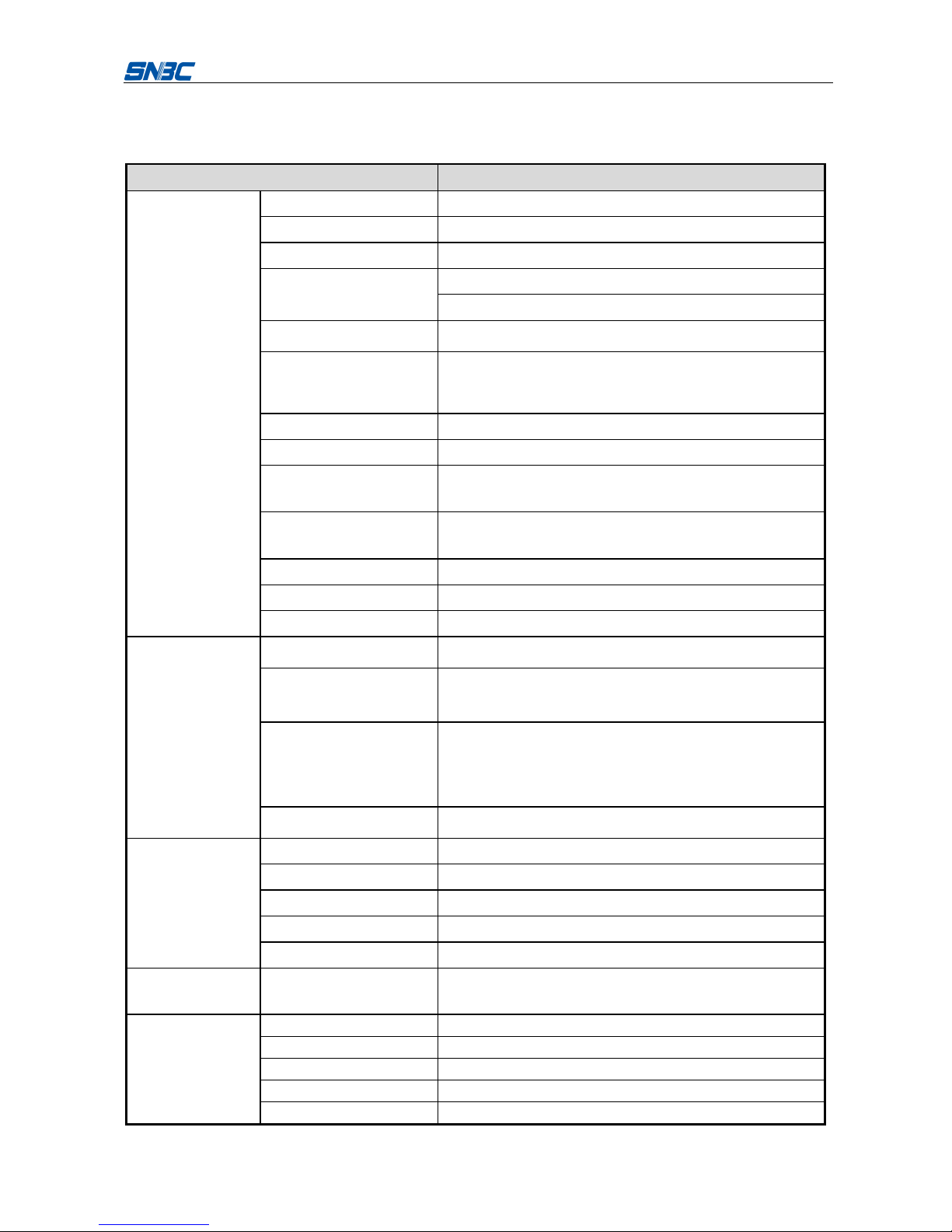
2.1 Technical specifications
Item
Parameter
Printing
Print method
Thermal
Resolution
203/305DPI
Paper width
48~82.5±0.5 mm
Print width
Max.80mm (3.2 ")
Max.640 dots
Print height
Max: 800mm
Min: 70 mm
Print speed
200DPI 1ST (Max): 275 mm/s
200DPI 2ST(Max): 150 mm/s
300DPI 1ST (Max): 180 mm/s
300DPI 2ST (Max): 100 mm/s
RAM memory
SDRAM: 8/32 MB
Flash memory
2MB/4MB (depending on the size of font library)
Print head temperature
detection
Thermal resistor
Print head position
detection
Micro switch
Paper/mark detection
Photoelectric/Mechanical photoelectric sensor
Paper near end detection
Photoelectric sensor
Communication interface
USB, RS-232 (optional)
Barcode
Character
Image
Barcode
CODE128, ITF , UPC-A, UPC-E, EAN13, EAN8
CODE39, CODE93, CODABAR, PDF417, GS1, QR
Character set
Standard characters, compressed characters
Optional Asian character set (simplified Chinese, traditional
Chinese, Japanese, Korean)
Character processing
All characters can be enlarged 1 to 6 times vertically and
horizontally.
Rotation print (0°, 90°, 180°, 270°);
Bold, white/black reverse, underline.
Image
BMP bitmap can be downloaded to RAM and FLASH;
Support direct bitmap printing
Media
Paper type
Continuous paper/marked paper
Paper roll OD
Max.300mm
Core ID
ф10-60mm
Paper thickness
55~100 um
Thermal layer
Outward / Inward
Power consumption
+24V power supply, at
room temperature, average
value
2.5A
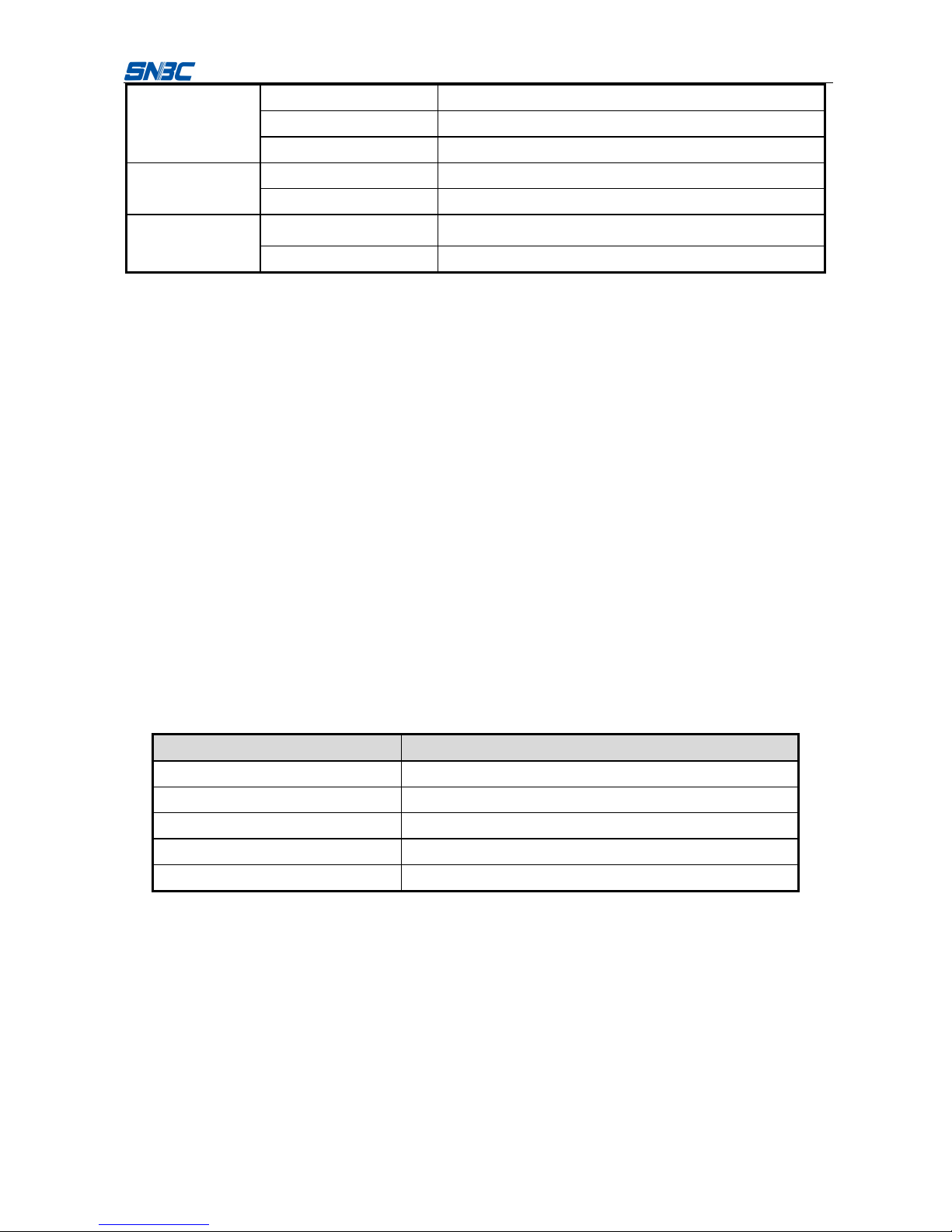
PRESENTER
Paper out detection
Photoelectric sensor
Paper out speed
600~1000 mm/s
Retraction detection
Photoelectric sensor
Retraction speed
≥1000mm/s
Paper out mode
Retraction/holding/closing/ejection/throw-out (optional)
BK-T680 User’s Manual
4
Reliability
Print head lifetime
≥100Km
Cutter lifetime
≥1, 000, 000 (65μm thick thermal paper)
MTBF
360,000 hours (main board)
Environmental
requirements
Operating environment
0~50℃, 20~90%RH(40℃)
Storage environment
-40~60℃, 20~93% RH(40℃)
Physical features
Overall size
161(L) X 123.2(W) X 120.9(H)
(excluding paper holder, paper roll, including control board)
Weight
About 1.8 Kg (excluding paper roll and paper holder)
Notes:
DPI: dots per inch. (1 inch≈25.4 mm);
The real print speed is related to data transmission speed, print darkness, print duty ratio, control
commands and power supply voltage, etc. The print speed may be lower than the value in the
above table.
PRESENTER is a mechanism used to accommodate paper at the front end of the printer.
2.2 Paper specifications
Paper type: continuous paper/marked paper
Paper supply mode: paper roll
Paper width: 48~82.5±0.5 mm
Paper thickness: 55um~100um
Thermal layer: outward / inward
Paper roll specifications:
Optional core ID: ф10-60mm
Max. paper roll OD: ф300mm
2.2.1 Recommended paper:
1) Recommended continuous paper specifications:
Paper model
Manufacturer
TF50KS-E2C
Nippon Paper Industries Co., Ltd.
F240AC/F220-VP
Mitsubishi Paper Mill CO., LTD.
KF060-FEAH
NEW OJI Paper CO., LTD.
F70NA
FUJI PHOTO FILM CO., LTD.
FV230A1
MITSUBISHI PAPER MILL CO., LTD.
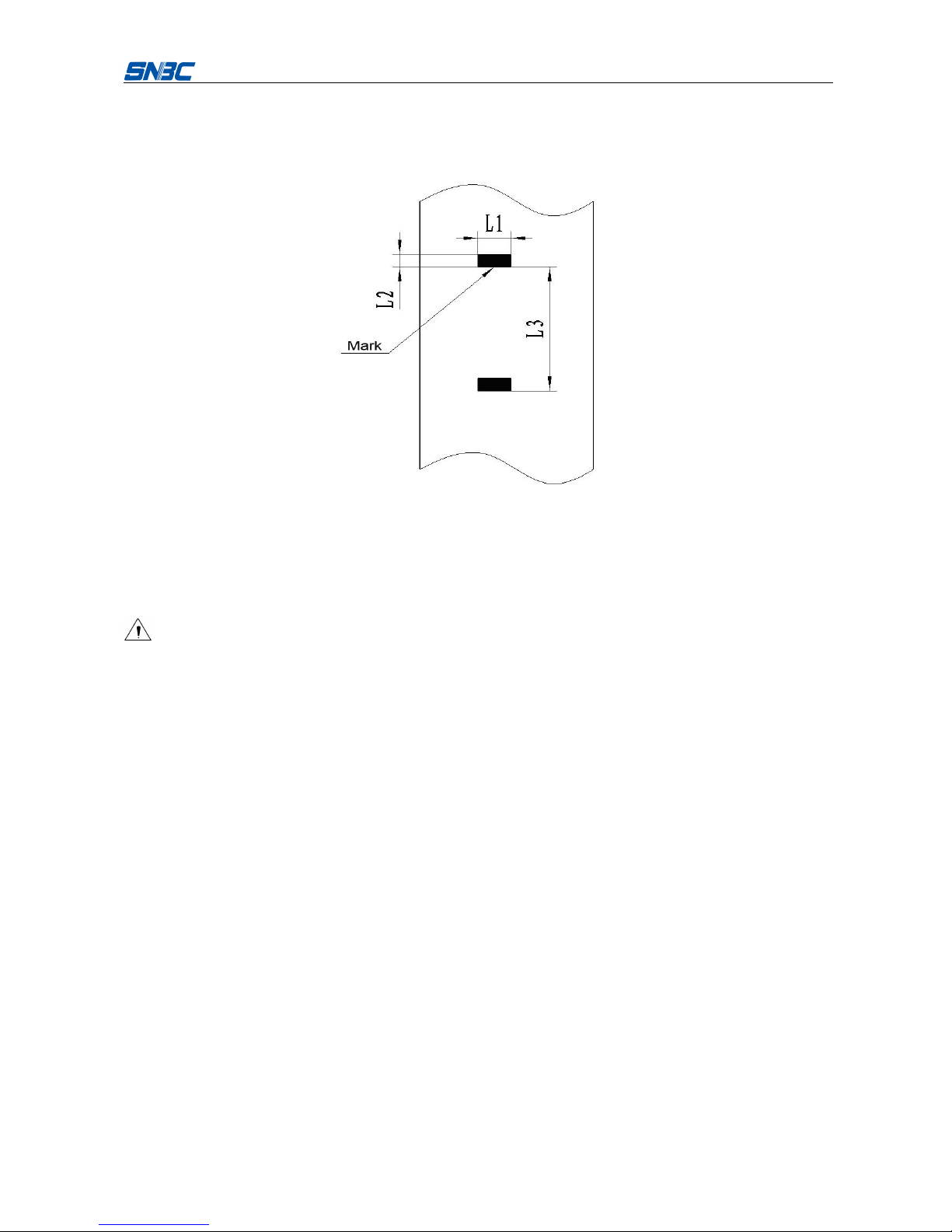
2) Recommended marked paper specifications:
The marked paper should not only meet the requirements for standard paper, but also meet the following
requirements:
Mark position
User can select the position of mark (located on thermal layer/non-thermal layer);
When selecting mark, it is recommended to use the following parameters:
L1 mark width: 8mm≤L1≤paper width
L2 mark height: 4mm≤L2≤8mm
L3 mark interval: 58mm≤L3≤305mm
BK-T680 User’s Manual
5
The reflectivity of marks is no more than 10%; the reflectivity of other parts of the ticket within
mark width along paper feeding direction is no less than 75%.There should be no character or
pattern such as advertisement between two marks.
Notes:
Because of paper shaking in paper feeding and paper parameter difference, the mark position
may have a tolerance of ±1mm;
The mark height can be set by adjusting the printer configuration.
Caution:
Please use the recommended paper or its equivalents. Using other types of paper may affect print
quality and even reduce the print head lifetime;
Do not stick the paper to the paper roll core;
If the print paper is contaminated by chemical or oil, it may discolor or be less heat sensitive,
which will greatly affect the print quality;
Do not rub the paper surface with a nail or hard metal, otherwise it may discolor;
When the temperature goes up to 70℃, paper will discolor. So please be careful of the effect of
temperature, humidity and sunlight.
BK-T680 User’s Manual
6
3 Structure and functions
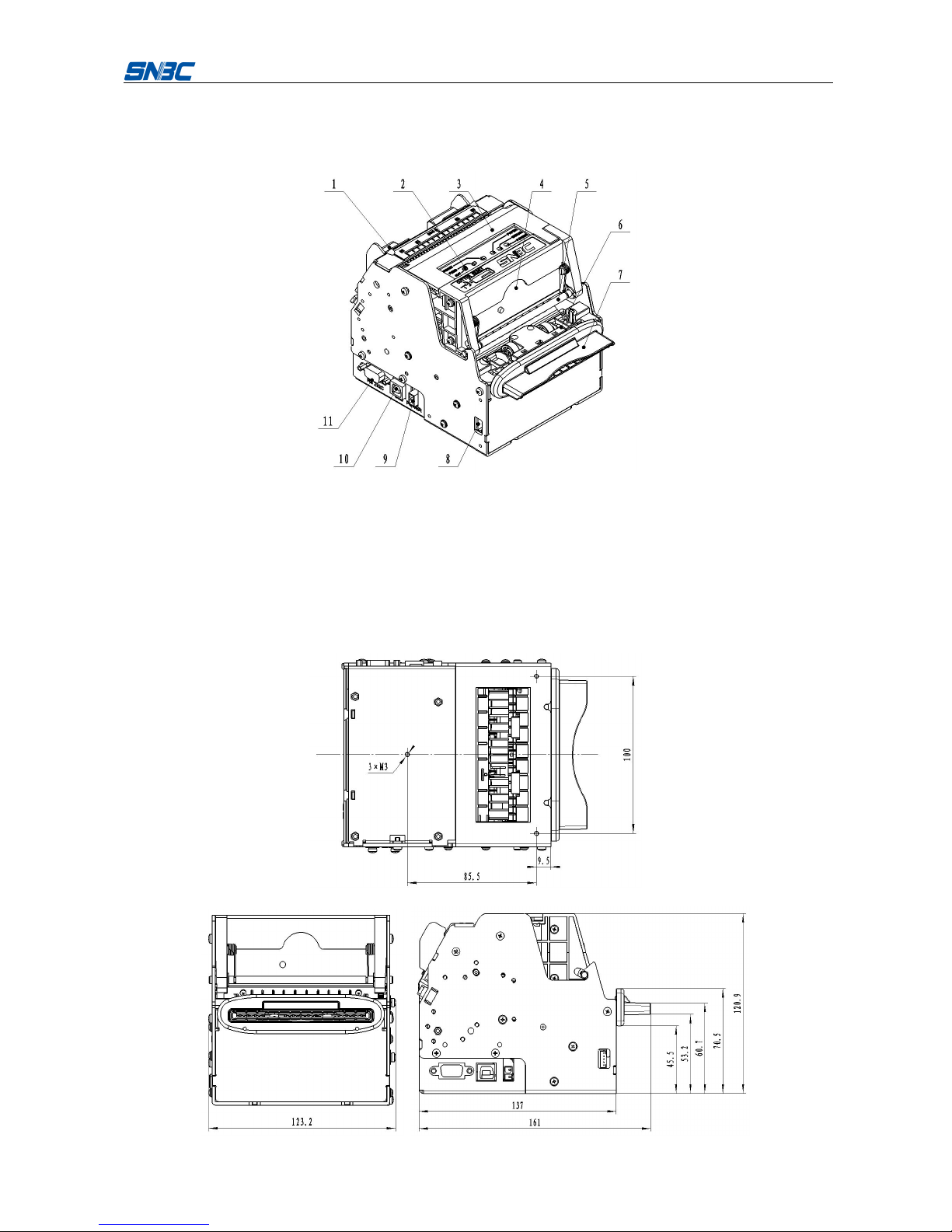
3.1 Appearance
Figure 3.1-1 BK-T680 printer appearance
1 —paper guide
2 —button
3 —print module
4 —cutter
5 —top cover locking axis
6 —Presenter
7 —LED paper outlet mouth
8 —paper near end sensor socket
9 —power interface
10 —USB interface
11 —serial interface
3.2 Overall size

BK-T680 User’s Manual
7
Figure 3.2-1 Overall size of printer with presenter
Figure 3.2-2 Overall size of printer with presenter and anti-jam module
Note: The overall size of the printer only with anti-jam module is the same as that of figure 3.2-2.

BK-T680 User’s Manual
8
3.3 Print module and controlling parts
The controlling parts include circuit board and the corresponding adjustment buttons, interfaces, etc.
3.3.1 Appearance of print module and controlling parts
Print module mainly consists of print mechanism, paper cutting mechanism, etc. Please refer to figure
3.3-1 for details:
Figure 3.3-1 Appearance of print module and controlling parts
1 —paper guide
2 —POWER LED
3 —ERROR LED
4 —PAPER LED
5 —RESET button
6 —FEED button
7 —CUT button
8 —cutter
9 —top cover locking axis
10 —power interface
11 —USB interface
12 —serial interface
3.3.2 Print module description
Top cover locking axis
Press the top cover locking axis slightly to separate the print platen roller from print head so as to
clear some errors.
CUT button
Press this button to cut paper in any status (no matter the printer alarms or not).
FEED button
If the printer doesn’t alarm, press down this button to feed paper;
Press this button continuously to feed long distance;
Pressing and holding the FEED button while powering on the printer for three seconds, the
printer will start and print a self-test page, the printout of which depends on the printer
configuration.
Note:
Make sure that there is paper in the printer and the print head is not uplifted before starting self-test
(for self-test page, please refer to Appendix 1 Self-test page).
RESET button
When pressing down this button, the printer will execute its reset and the print data will be cleared.
PAPER LED (red)
When paper end or paper near end is detected, PAPER LED will be always on; If the paper is in

BK-T680 User’s Manual
9
normal status, PAPER LED will not be on.
ERROR LED (red)
It indicates different status of printer. Normally, ERROR LED is not on; when errors occur (for
example, paper end), ERROR LED will flash to give alarms.
Note:
ERROR LED flashes when the printer is executing macro definition.
POWER LED (green)
It indicates whether the power is on or not, and it is always on when the power is turned on.
Caution:
Print head: The print head and motor generate heat in use; please do not touch them just after
operation.
3.4 Presenter
Figure 3.4-1 Presenter appearance
1.—Presenter upper path 2.—Presenter floating roller 3.—LED paper outlet mouth
4.—Paper near end sensor socket 5.—Presenter turning board
6.—Presenter drive roller
7.—Paper out sensor: to detect paper status and determine whether it is taken away or not.
8.—Retraction sensor: to detect whether paper is retracted correctly or not in the paper retraction
process.
BK-T680 User’s Manual
10
4 Installation and suggestion
4.1 Unpacking
Open the carton and check whether all items listed on the packing list are included or have any damages.
In case of damages or missing items, please contact your dealer or the manufacture for assistance.
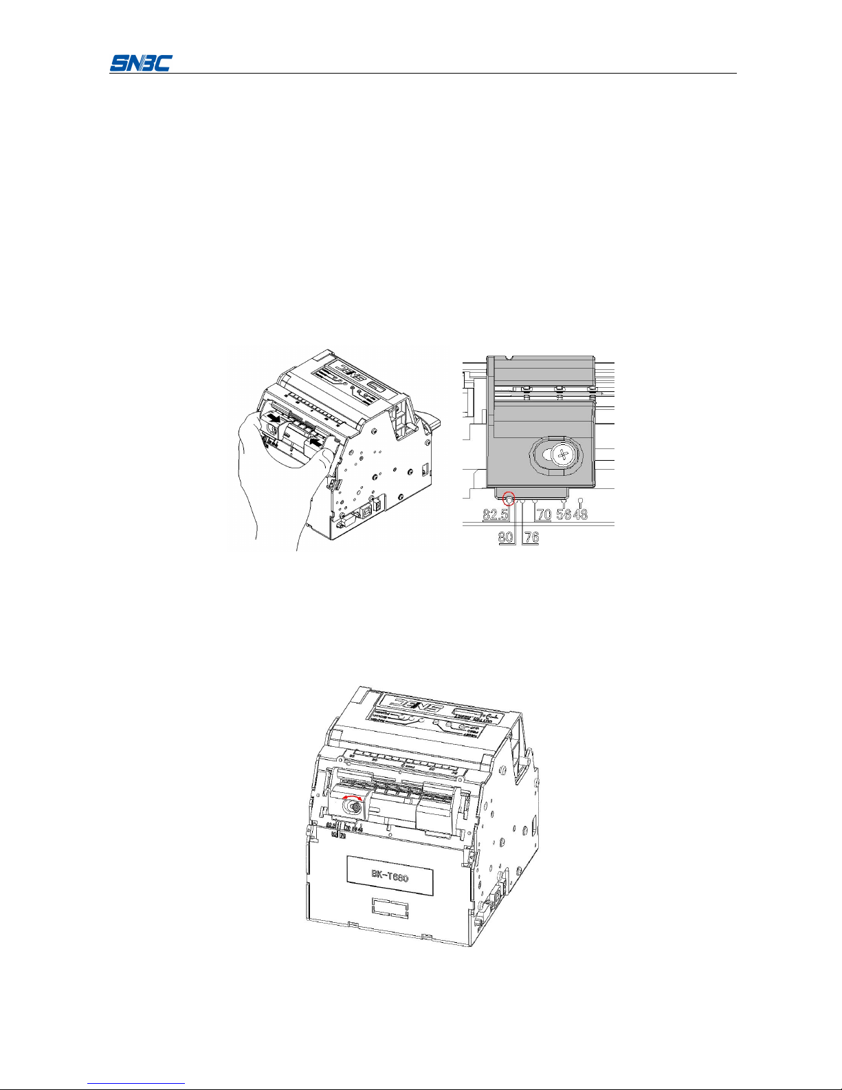
4.2 Adjusting paper guide
Open the carton and adjust the paper guide to meet different paper width before installing printer.
BK-T680 can use paper adjustable from 48 to 82.5mm. Adjust the paper guide to right position as
showed in the following figure.
Three are six scale marks on bottom cover of paper guide: 82.5mm, 80mm, 76mm, 70mm, 56mm,
48mm. Remove the paper guide to adjust the gap to be aligned with the dot of target scale mark.
Figure 4.2-1 Adjusting paper guide
Note: Unscrew the screws that fix the paper guide in anticlockwise direction before removing the paper
guide (Don’t need to disassemble the screws completely.), and then tighten the screws after the paper
guide reaches the right position. (The default configuration of the screw is not assembled unless the
customer requires.)
Figure 4.2-2 Adjusting the paper guide fixing screws

BK-T680 User’s Manual
11
4.3 Adjusting mark sensor position
The position of mark sensor on BK-T680 printer can be adjusted to right or left side, thermal or
non-thermal side. The mark sensor needs to be adjusted when following cases occur:
The position of mark on paper is inconsistent with the position of mark sensor (including right/left
side, thermal/non-thermal side).
Note: Please adjust the mark sensor before installing cantilever holder.
Steps to adjust the position of mark sensor to right/left side:
1) Make the cross screw driver deep in the printer in the direction shown in the figure 4.3-1, and then
rotate it in the direction shown by the green mark to adjust the position of mark sensor;
Figure 4.3-1 Adjusting mark sensor position
2) The bulge that aligns with scale mark indicates the relative position of mark sensor to the center
line of path as shown in the figure 4.3-2. Take out the cross screw driver when the sensor gets to
the right position.
Figure 4.3-2 Indicating mark sensor position
Steps to adjust the position of mark sensor to thermal/non-thermal side:
1) Refer to step 1 in “5.1 Cleaning mark sensor” to remove the paper guide module;
2) Refer to step 2 in “Cleaning mark sensor” to remove the screw module of mark sensor, and
exchange the upper and the lower screw modules of mark sensor, then the position of mark
sensor (thermal/non-thermal side) is changed.
BK-T680 User’s Manual
12
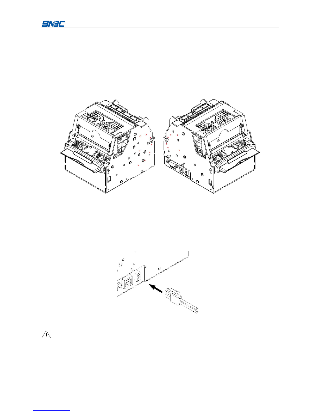
4.4 Grounding
To ensure the printer is well grounded, connect the grounding cable as showed in the figure 4.3-1.
1) Necessary tools: cross screw driver.
2) Fix the grounding cable to one of the fixing holes (14 pcs of M3 holes, which are installed on the
no-installing side of printer paper holder as shown in figure 4.4-1) when installing the printer, and
complete the connection of grounding cable.
3) Note: The screw length is 4mm.
Figure 4.4-1 Grounding position
4.5 Connecting power adapter
1) Ensure the printer power is turned off;
2) Insert the power adapter cable into the power interface at the bottom of the printer as shown in the
figure 4.5-1;
3) Connect the input power supply of power adapter.
Figure 4.5-1 Connecting power adapter
Caution:
Use the recommended power adapter or its equivalents.
Connect power adapter connector at a right angle between pin and socket.
When connecting or disconnecting the cable connector of power adapter, always hold the connector
shell and don’t pull the cable forcibly.
BK-T680 User’s Manual
13
Avoid dragging or pulling the cable of AC adapter, otherwise the cable may be damaged or broken,
and a fire and electric shocking may be caused accordingly.
Avoid placing the power adapter near an overheating device, otherwise the surface of cable may
melt and cause a fire or electric shock.
If leaving the printer idle for a long time, please disconnect the power adapter of printer.
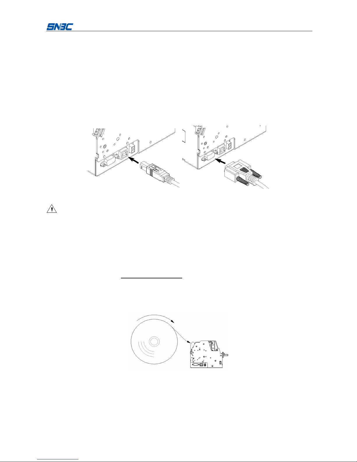
4.6 Connecting interface cable
1) Make sure that the printer has been shut down, (Sign “O” in power switch is pressed down);
2) Connect the interface cable to the corresponding interface (refer to figure 4.6-1);
3) Connect the other end of the cable to PC.
Figure 4.6-1 Connecting interface cable
Caution:
Make sure the interface cable is connected in correct direction.
When connecting or disconnecting the cable connector of power adapter, always hold the connector
shell and don’t pull the cable forcibly.
4.7 Installing paper roll and loading paper
Before starting to install the paper roll, make sure the specification of paper roll is in conformity with
printer requirements (refer to 2.2 Paper specifications).
4.7.1 Steps for installing paper roll
The paper roll installation of BK-T680 is quite easy, detailed operations are as follows:
1) Turn on the power and place the paper head into the paper feeding path as shown in figure 4.7-1;
Figure 4.7-1 Paper loading
2) The roller starts rotating when paper sensor detects paper presence to finish semi-automatic
paper feeding.
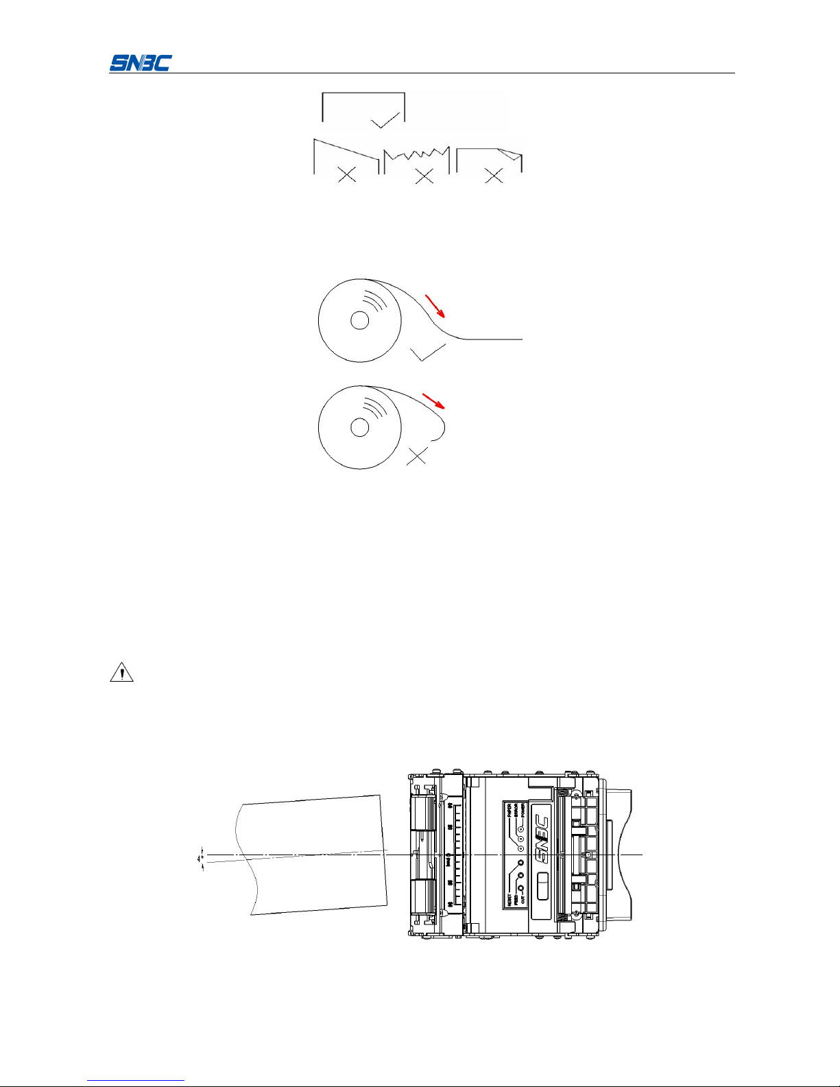
Note: Before loading paper, cut the paper head trimly as showed in the following figure.
BK-T680 User’s Manual
14
Figure 4.7-2 Paper head
Note: Before loading paper, make the radian of paper flat to ensure that paper loaded enters printer path
smoothly.
Figure 4.7-3 Paper head radian
4.7.2 Semi-auto paper loading
1) Turn on the power and the buzzer beeps for alarming paper end;
2) Refer to figure 4.7-1, push the paper into paper inlet slightly for a certain distance, and release the
hand when the platen roller starts to rotate and hold the paper;
3) The printer starts to feed paper and is possible to print when paper head stops at the normal
printing position after printer stops feeding paper.
Caution:
When pushing the paper into feeding path, the strength should be well-distributed and gentle, try to
make the front head of the paper parallel to the feeding paper path and the intersection angle
between paper center line and printer center line no more than 4° to avoid paper jams.
Figure 4.7-4 Paper loading

BK-T680 User’s Manual
15
4.8 Installing printer
BK-T680 embedded printer is a printer with easy and reliable operation, and it has good adaptability of
installing and good maintenance. It adopts modularization design, active connection, flexible
maintenance and operation station according to the embedded characters. Please refer to the content of
this section when designing the whole machine that the printer will be used for, to ensure the reliable and
effective work of BK-T680 embedded printer.
4.8.1 Installation notice
1) Install the printer on a flat and stable place. Recommend installing horizontally, the inclination angle
shouldn’t exceed ±15° (paper feeding direction). Inclination in other directions should be no more
than ±1°;
2) Suggest that the flatness of fixed surface should equal and less than 0.3mm;
3) Keep the printer far away from water source.
4) Do not place the printer in the place exposed to vibration and impact.
5) Ground the printer safely.
4.8.2 Fixing printer
Figure 4.8-1 Fixing printer
1) The position of hole fixing printer please refer to figure 3.2-1 and figure 3.2-2;
2) Screw length (H) ≤ bottom board thickness (h) + 6mm. For example, when the thickness of bottom
board is 4mm, the length of screw should not exceed 10mm.
Table of contents
Other Shandong Printer manuals

Shandong
Shandong BTP-2002NP Owner's manual

Shandong
Shandong BTP-M280 User manual

Shandong
Shandong U80II User manual

Shandong
Shandong BTP-2002NP User manual

Shandong
Shandong BTP-R880NP User manual

Shandong
Shandong BTR-R980 User manual

Shandong
Shandong BT-T080R Owner's manual

Shandong
Shandong BTP-R580 User manual

Shandong
Shandong BT-T080 plus Owner's manual


