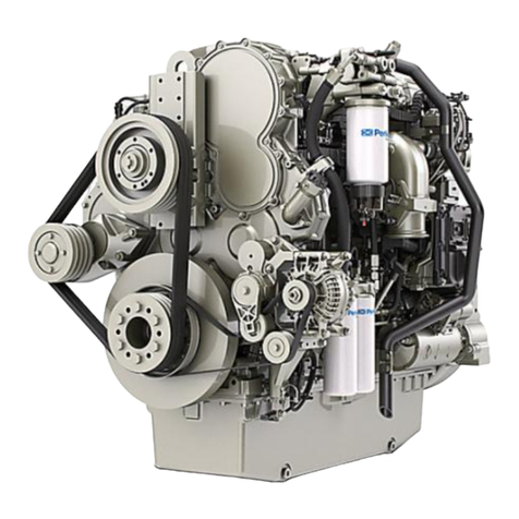
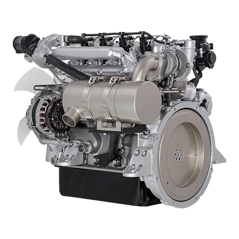
Shanghai Diesel Engine SC11CB User manual

Operation and Maintenance Manual
ForSC11CB Diesel Engine
121-SM-06+A
ShanghaiDieselEngineCompany, Ltd
January 2008

Foreword
SC11CB dieselengine,jointlydevelopedbySDECincooperationwithFEVofGermanyon
thebasis of 6C121 seriesdieselengines,isanewdieselengineoflowemissionandlowfuel
consumption.Withturbochargedorturbocharged/inter-cooled,theenginepowerrangesfrom162
kWto235 kW.ComplyingwithChinesenationalemissionstandardsofstage1andstage2,
SC11CB dieselengineisanidealpowerforapplicationsofvariousconstructionmachinery,
generatorset,marineandvehicle.
SC11CB dieselengineadoptsmetricthreadsystemtoall threadedpartsfortheconvenience
ofapplication.
Forbetterandsafeoperationoftheengine,readandstudytheinformationandinstructionsin
thisManualcarefullybeforestartingoperation.
Somespecificationsand illustrationsinthispublication mayslightlydifferfromthoseof
yourenginebecauseofcontinuousimprovementonperformanceandstructurethatmayhave
causedchangestoyourengine.Thechangeswill becoveredinnextedition.
Yourcommentsandsuggestionsonthemanualwill bemuchappreciated.Pleasecontactour
sales service center.

SafetyInformation
1. Providesecuredprotectiveguardsandcoversforall externalrotating partstopreventpersonal
injury.
2. Stoptheenginebeforeconductingadjustmentorrepairtoit and itsdrivedevices.
3. Donotwearlooseworkclotheswhenworkingaroundengineormachine.
4. Wearearsplugstopreventhurtofhearingwhiletheengineisrunning inanenclosedshop.
5. Wearprotectiveglasses,workclothes, safetyhatandotherprotectiveequipmentwhen
necessary.
6. Wearprotectiveglassesandworkclotheswhilecleaningwithpressureairorpressure
water. Themaximumairpressureandwaterpressureshouldnotexceed205 kPaand 275 kPa
respectively.
7. Donotsmokewhenrefillingfueltopreventburningoffuelfumes.
8. Donotsmokewhencheckingtheelectrolytelevelofabatterybecauseit mayemit flammable
fumes.
9. Avoidcontactingelectrolytewithyourskinandeyeswhilerefilling becauseit isacid.
10. Besurethereisproperventilationintheplace whereengineisunderoperation.
11. Donotattempttodorepairthatyoudon tunderstandtoavoidabadconsequence.
12. Removeall tools,wiresandotherarticlesfromtheenginebeforestarting.
13. Wipeoff any overflowingoflubeoil, fuel, coolantandotherliquidson theenginebefore
starting.
14. Adoptaproperandsafetymethodfordisposalofwasteoil.
15. Keepoilyragsawayfromtheengineandputtheminafireproofcontainer.
16. Donotkeepflammableliquidsneartheengine.
17. Disconnectandwrapbatterygroundingwirewithinsulatetapebeforerepairing the engine to
preventunexpectedenginestarting.
18. Disconnectthebatterytotheenginewhenit will notbeenusedforalongtimeorwhenit is
underrepairtoavoidunexpectedstarting.
19. Donotstarttheenginewhenthelinkageofagovernorisdisconnected.
20. Bepreparedforstoppingairsupplyatanytimeforanewlyrepairedengine, andstopair
supplyimmediatelyoncetheenginerunsawayafterstarting.
21. Becarefulwhenrefillingcoolantintoclosedcoolingsystemwhiletheengineisrunningto
avoidbeinghurtbycoolantsteam. Openthepressurecaponlywhenthecoolanttemperature
isbelow70 .

NecessaryInformationforEngineOperation
1. Checkanewlyinstalledengineforleaksbeforestarting.
2. Makegood “Starting Preparation”foreveryenginestarting.Remembernottoapplyanyload
whenstartingengine.
3. Breakintheenginefor60 hoursbeforetheoperationofanewengineoranoverhauledengine.
4. Runtheenginewithoutload for3~5minafterstartingand thenincreaseload gradually. Runthe
enginewithfull loadonly whentheenginecoolanttemperaturereachesover75 , oil temperature
over50 and oil pressureover0.4 MPa.
5. Disassembletheturbooilinletpipeofturbochargerandfilltheturbochargerwith50~60 ml
lubeoil fromoilinletportwhenoperatinganewengineoranenginewithreplacedturbocharger
topreventtheturbobearingfrombeingdamagedbecauseofnolubeoil.
6. Donotusemixtureoflubeoilswithdifferentspecificationswhenrefilling.
7. Donotstarttheenginewithoutairfilter.Airfiltercanpreventdustandparticlesintotheengine
thusavoidingearlyenginewear.
8. Observeengineoperation andvaluesindicatedby all gageindicatorswhentheengineruns.
Haveemergentenginestoppingmeasuresandtakethemwhenevernecessarytoavoidengine
seizingarisingfromengineoverheatduetolackofcoolantordecreasedoil pressure.
9. Checkfuellineforleaksregularlywhiletheenginerunsbecausethefuellineisontheexhaust
sideoftheengine. Removeanyproblemstimelytoavoidfire.
10. Donotruntheenginewhenadjustingtheenginebelttensionanddrivedevice.
11. Unloadengineslowlytopreventtheenginefromrunningawayduetomalfunctionofthe
governorresultingfromsuddendecreaseofload.
12. Replacethemalfunctionedthermostattimelyanddonotoperatetheenginewithoutthermostat.
13. Drainall coolantintheengineafterit isstopped,especiallywhentheengineisusedunder
freezingcoldweatherwithoutusinganti-freezeadditivetopreventtheblockandotherrelevant
partsfromfrozen fracture.
14. Checkall connectingboltsandnutsregularlyforloosening.
15. Donotremoveanyleadsealsontheengineandmakeadjustment atdiscretion.Sendthe
enginetoresponsibleshopsforadjustmentorrepairifnecessary.
16. Performdailyandthree-levelmaintenancesaspertherequirementsandinstructionsofthis
Manual.

TableofContents
Foreword
Safety Information
OperationInformation
1GeneralInformation ……………………………………………………………………1
EngineViewsandInformation ………………………………………………………… 4
EngineIdentification …………………………………………………………………… 4
1.2.1EngineNameplate ………………………………………………………………… 4
1.2.2 EngineModel ……………………………………………………………………………4
1.2.3PartNumber ………………………………………………………………………………5
1.3EngineSpecifications ………………………………………………………………………5
1.3.1BasicEngineParameters …………………………………………………………………5
1.3.2 MainEnginePerformanceData …………………………………………………………6
1.3.3 EnginePerformance Curves ………………………………………………………………8
1.4 ClearancesandWearLimitsofMainComponents ………………………………………10
1.5 TorquesforMainBolts …………………………………………………………………11
1.6 TorqueforGeneralFasteners ………………………………………………………………11
2. MainComponentsAssemblyData ………………………………………………………13
2.1 CylinderBlock …………………………………………………………………………13
2.2 CamshaftBearings …………………………………………………………………………14
2.3CylinderLiners …………………………………………………………………………14
2.4 ConnectingRods …………………………………………………………………………16
2.5 PistonsandPiston Rings ………………………………………………………………17
2.6TimingGears ………………………………………………………………………………18
2.7 Camshaft …………………………………………………………………………………18
2.8 ValveRockerArmsandTappets …………………………………………………………19
2.9Valves ……………………………………………………………………………………20
2.10CylinderHeadand ValveCover ………………………………………………………21
2.11 Crankshaft ………………………………………………………………………………22
2.12 FlywheelHousing ……………………………………………………………………23
2.13 Flywheel ………………………………………………………………………………26
2.14Alternator ………………………………………………………………………………28
2.15Starting Motor …………………………………………………………………………29
3. MainEngineSystem ……………………………………………………………………30
3.1 FuelSystem ………………………………………………………………………………30
3.2 Intakeand ExhaustSystem ……………………………………………………………31
3.3Lubrication System…………………………………………………………………………33
3.4Cooling System …………………………………………………………………………35
3.5 ElectricalSystem …………………………………………………………………………36
3.5.1 StartingMotor …………………………………………………………………………36
3.5.2 ChargeableAlternator …………………………………………………………………37
3.5.3Battery ………………………………………………………………………………37
3.5.4 Shut-off Solenoid ……………………………………………………………………37

3.5.5Wiring Arrangement ………………………………………………………………37
3.6 ColdStartAid ……………………………………………………………………38
4EngineOperation……………………………………………………………………… 39
4.1 Fuel …………………………………………………………………………………39
4.2Lubricating Oil ………………………………………………………………………39
4.3 Coolant ………………………………………………………………………40
4.4EngineStarting ………………………………………………………………………41
4.5 EngineOperationand Stopping ……………………………………………………42
5InspectionandAdjustment ……………………………………………………43
5.1ValveLash ………………………………………………………………………43
5.1.1 InspectionofValveLash ……………………………………………………43
5.1.2AdjustmentofValveLash ……………………………………………………44
5.1.3 Observation ofValveRotation ……………………………………………………45
5.2 InjectionTiming ………………………………………………………………………46
5.2.1 TDCon CompressionStrokeforNo1Piston …………………………………46
5.2.2 Inspection andAdjustmentofFuelInjectionTiming …………………………………46
5.3 InjectionNozzle ………………………………………………………………………48
5.3.1 NozzleOpening PressureTest ………………………………………………………48
5.3.2Disassemblyand Cleaning …………………………………………………49
5.3.3 TipLeakageTest ………………………………………………………………………49
5.3.4SprayQualityTest ………………………………………………………………………50
5.3.5 LeakTestofNozzleCouples ……………………………………………………50
5.4 LubricationSystem ………………………………………………………………………50
5.4.1OilConsumption high ……………………………………………………50
5.4.2 Oil PressureLow ………………………………………………………………………51
5.4.3Oil PressureHigh ………………………………………………………………………52
5.4.4 OilPumpBearing Worn ……………………………………………………52
5.5 Belt Tension ………………………………………………………………………52
6. Maintenance ……………………………………………………53
6.1 MaintenanceWhenNecessary …………………………………53
6.1.1 CleaningCoolingSystem ……………………………………………………53
6.1.2AirFilterService ……………………………………………………54
6.1.3 FuelFilterService ……………………………………………………57
6.2Maintenance Schedule ……………………………………………………59
6.3 DailyMaintenance(Every8Operating Hours) …………………………………60
6.4 Every50 Operating Hours ……………………………………………………61
6.5 Every250Operating Hours ……………………………………………………62
6.6 Every500Operating Hours ……………………………………………………65
6.7 Every1000Operating Hours……………………………………………………66
6.8 Every2000Operating Hours ……………………………………………………66
7Troubleshooting ………………………………………………………………………69
7.1 GeneralRequirementson Troubleshooting ………………………………………………69
7.2 CausesandCorrections …………………………………………………………………69


1
1. General
1.1 EngineViewsand Information
Fig1-1 SC11CBDieselEngineforConstructionMachinery(Turbocharged)

2
Fig1-2 SC11CBDieselEngineForVehicle(TurbochargedandInter-cooled)

3
Fig1-3 EngineViewandAuxiliaryArrangementofSC11CB DieselEngine
(1)Airfilter(2)Turbocharger(3)Turbineoutletpipe(4)Muffler
(5)Crankcasebreather(6)Fan(7)Liftingplate(8)Oil refillingport
(9)Fuelinjectionpump(10)Fuelfilter(11)Fuelprimingpump
(12)Crankcaseventpipe(13)Connectionforspeedsensor(14)Pulleybelt
(15)Flywheelhousing(16)Oil drainport(17)Oil dipstick(18)Oil filter
(19)Oil cooler(20)Torsionalvibrationdamper(21)Waterpump

4
1.2 EngineIdentification
1.2.1 EngineNameplate
SC11CB dieselenginehasapermanentnameplatethatcontainsimportantinformationsuchas
model,ordernumber,productionnumber,dateofdelivery,ratedpower,ratedspeed,etc.Record
thatinformationinthelogsofyourengineorequipmenttowhichtheengineisappliedand
providethemwhencontactingusforrepairorqualityfeedback.Theinformationishelpfulforus
toprovidegoodsolutionstoyourproblems.
Thenameplateisusuallylocatedontheleftsideofenginecylinderheadandneargear
housing.
Fig1-4 NameplateofSC11CB DieselEngineforConstructionMachinery
Keepthenameplatefree fromdamagebecausetheinformationonit isimportantforrepair
peopletogettherelevantspecificationsofengineand checkthepartnumbersofpartsthatneed
repairing.
1.2.2 EngineModelandOrderNumber
EnginemodelconsistsofArabicnumbersand Englishletterswithmeaningsasfollows:
SC11CB
EmissionLevel
Application
RatedPower(inPS)
StructureFeature(developedwithFEV)
C121 DieselEngineFamily
Displacement
ShangchaiPower(Brand ofSDEC s
Products)
Symbolofapplication
G-- ConstructionMachineryQ--VehicleD---Gen-set(forland)P-- Agriculturemachinery

5
CA--Marineengine(leftsideengine)C
F
-- Auxiliarymarinemachinery
EngineordernumberconsistsofArabicnumbersandEnglishletterswithmeaningsasfollows:
CB
Structurechange
Structurefeature(developedwithFEV)
C121 SeriesDieselEngineFamily
1.2.3 PartNumber
SC11CB dieselengines,jointlydevelopedwithFEVofGermanyonthebasisof6C121 series
dieselengines,isanewdieselengineoflowemission and lowfuelconsumption.Threaded
connectionofthisenginediscardsoriginalinchsystemandadoptsmetricsystem.Partnumberfor
theengineconsistsofthree kinds:1)partnumbersofsome6C121 dieselenginepartsand
components,2)partnumberofnewlydesignedpartsand components,3)partnumbersofmetric
threadedparts.
For6C121 engine,thepartnumberhastwokinds:oneconsistsof6wordscontainingArabic
numbersandEnglishletters, like6N9915, 7C3906;theotherconsistsof7 straightArabicnumbers
like1007861, 1218015.
Fornewlydesignedpartsand components,thepartnumberconsistsof6wordscontaining
ArabicnumbersandEnglishletterslike06CB003, 12AL006.
Formetricthreadedparts,thepartnumberadoptspartnumberofC6121 enginepartnumber
plusprefix “M”likeM6N9915, orpartnumberofnewlydesignedpartplusprefix “M”like
M06CB003.
Forthepurposeofidentifications,partnumberswill beusuallycast,forged,stamped,etched
orotherwisemarkedindeliblyonthepartsofSC11CBdieselengineornameplatesmarked
indeliblyonpurchasedassemblies.Look atthepartnumberofapartcarefullywhenrepairingand
replacing. Contactourservicedepartmentwhenyouhaveprobleminidentifyingapartnumber.
Therearesomesuffixes “M”, “X”, “U”etc.tothepartnumberonhardware,whicharecodes
indicatingpurchasingsourcesaroundtheworld.Suffix “M”meansthatthepartismadeinChina.
Partsofsamekindwiththesamepartnumberbutfromdifferentsourcesareexchangeable,like
6N9915Mand 6N9915 canbeexchanged;or1007861M,1007861 and 1007861Ucanbe
exchanged.However,metricthreadedpartswithprefix “M”cannotbeexchangedwiththeir
correspondingpartsininchsystem, likeM7E6167 and 7E6167 cannotbeexchanged.
1.3 EngineSpecifications
13.1 BasicParameters
SC11CB
Type In-line, 4-stroke, watercooled,directinjection
Bore×Stroke(mm×mm) 120.65×152.4
Numberofcylinders 6
Totaldisplacement(L) 10.45
Firingorder 1-5-3-6-2-4
Rotation
(viewedfromflywheelend) Counterclockwise
Aspiration Turbocharged Turbochargerandinter-cooled

6
Orderofcylindersandvalvesviewedfromgearendisasshowedbelow:
Fig1-5 SchemeofCylindersand Valves
1.3.2 SpecificationsofMainEngineModels
Model SC11CB
220G1
SC11CB
300G2
SC11CB
320G2
SC11CB
290Q2
Atratedcondition
Speed r/min 2200 2100 2200
Power kW 162 220 235 213
BSFC g/kW.h
225 230
SmokeFSN ≤2.0
Atpeaktoquecondition
Speed r/min 1400
Toque Nm 880 1300 1390 1200
BSFC g/kw.h 210 205
Smoke FSN ≤2.5
Atotherconditions
Outletwatertemp. ℃≤99
Inletairtemp.
(afterintercooler)
℃─50
Exhausttemperature
(beforeturbine).
℃£700
BSOC g/kW.h
0.5 0.3
Acceleration smoke FSN ≤3.0
High idle r/min 2390 2310 2530
Lowidle r/min 750 650
Injectiontiming
°CA
(BTDC)
12~19 79
EmissionStage1 Stage2
Noise dB(A)
≤118 ≤119
Altitudelevel m 2400
Firstoverhaulperiod h 8000
Netweight kg 960 980
Intakevalve
Exhaustvalve
Flywheel

7
Model SC11CB
300Q2
SC11CB
320Q2
SC11CB
330Q2
SC11CB
340Q2
Atratedcondition
Speed r/min 2200
Power kW 220 235 242 250
BSFC g/kW.h
230
SmokeFSN ≤2.0
Atpeaktorquecondition
Speed r/min 1400
Torque N.m 1300 1320 1370 1390
BSFC g/kw.h 205
SmokeFSN ≤2.5
Atotherconditions
Outletwatertemp. ℃≤99
Inletairtemp.
(afterintercooler)
℃50
Exhausttemp.
(beforeturbine)
℃≤700
BSOC g/kW.h
0.5 0.3
Acceleration smoke FSN ≤3.0
High idle r/min 2530
Lowidle r/min 650
InjectionTiming °CA
(BTDC)
7
Emission Stage2
Noise dB(A) ≤119
Altitude m 2400
Firstoverhaulperiod
h 8000
Netweight kg 980

8
1.3.3 EnginePerformanceCurves
Fig1-6 FullThrottleCurveofSC11CB220G1 DieselEngine
Speed[r/min]
600 800 1000 1200 1400 1600 1800 2000 2200 2400
BSFC [g/kW.h]
205
210
215
220
225
230
Power [kW]
40
60
80
100
120
140
160
180
Torque [N.m]
650
700
750
800
850
900
950
1000

9
Fig1-7 Full ThrottleCurveofSC11CB 290G2 DieselEngine
Speed [r/min]
600 800 1000 1200 1400 1600 1800 2000 2200 2400
Torque [N.m]
900
1000
1100
1200
1300
BSFC [g/kW.h]
190
200
210
220
230
240
Power[kW]
50
100
150
200
250
1300
1200
1100
1000
900
250
200
150
100
50
Torque{Nm}
Power{kW}

10
1.4 ClearancesandWearLimitsofMainParts
unit: mm
Sizeand tolerance
No.
Item Bore Shaft Clearance Wear
limit
1 Mainbearing journaland
bearing Φ88.88±0.02 0.076-0.165 0.25
2 Crankpinsandconnecting
rod bearing Φ76.18±0.02 0.076-0.168 0.25
3 Crankshafttrust 0.122-0.579 0.85
4 Camshaftbushingand
camshaftjournal Φ58.80±0.06 Φ58.699±0.013
0.101±0.073
0.23
5 Camshafttrust4.83±0.05 4.65±0.03 0.18±0.08 0.64
6 Rockarmshaft/
bushing Φ18.448±0.013
Φ18.402±0.013
0.046±0.026
0.20
7 TappetboreandtappetΦ33.388±0.050
Φ33.287±0.013
0.101±0.063
0.30
8 Piston pinandpinbore Φ43.175+0.032
+0.025 Φ43.175±0.005
0.000+0.037
+0.020 0.05
9 Connectingrodbushing
and pistonpin Φ43.210±0.008
Φ43.175±0.005
0.035±0.013
0.08
10
End playofinjection
pump gearidle 31.45±0.08 31.19±0.08 0.26±0.16 0.86
11
Injectionpumpgearidle
and bushing Φ35+0.014
-0.006 Φ34.955±0.013
0.045+0.027
+0.007 0.20
12
Valvestems Φ9.441±0.008 Φ9.408
13
Boreinvalveguideafter
installation Φ9.456 (Min.)
Φ9.581
14
Oil ring thickness andoil
ring groove 4+0.04
+0.02 4-0.01
-0.03 0+0.07
+0.03 0.15
15
Clearance betweenends
oftoppistonring
installedinastandard
linerwithboresizeof
120.65 mm
0.35~0.5 1.5
16
Clearance betweenends
ofintermediatepiston
ring installedina
standardlinerwithbore
sizeof120.65 mm
0.65~0.85 1.5
17
Clearance betweenends
ofoilcontrolring
installedinastandard
linerwithboresizeof
120.65 mm
0.4~0.6 1.5
18
Cylinderliner Φ120.65+0.025
0 Φ120.75

11
1.5 TorqueforMainBolts
No Description Torque
1
Mainbearing bolt
1)41±4N·m
2)Thenturnby90°±5°
2
ConnectingRodbolt
1)4164 N·m
2)Thenturn90°±5°
3 Camshafttiminggearbolt 55±7N·m
4 Crankshaftpulleybolt 1) 312±25 N·m
1)312±25 N·m
5 Cylinderheadbolt(large)
1)156N·m
2)250±17N·m
3)250±17N·m
6 Cylinderheadbolt(small)43±7N·m
7 Adjustingscrewforvalvelash 296±7N·m
8 Valvecoverbolt 11±3 N·m
9 Alternatorpulleynut 112±10 N·m
10 Flywheelbolt 200±25 N·m
11 Fuelinjectionpumpdrivegearbolt 270±25 N·m
12 Flywheelhousingbolt 100±15 N·m
13 Bolt holdingfrontcrankshaftsealbase
135±15 N·m
14 Nutsecuringhigh pressurefuelline 40.6±6.8 N·m
1.6 TorqueforGeneralFasteners
Torquesformetricfasteners
Metricthread
TorqueThreadsize
(Metricsystem) N·m
M6 12±3
M8 28±7
M10 55±10
M12 100±20
M14 160±30
M16 240±40
M20 460±60
M24 800±100
M30 1600±200
M36 2700±300
Torquesforstandardhoseclamps(wormtype)
Torqueforclampingnewhose
WidthofclampN·m
16 mm(0.625 inch) 7.5±0.5
13.5 mm(0.531 inch)
4.5±0.5
8mm (0.312 inch) 0.9±0.2

12
Torqueforreinstallationorretightening
Widthofclamp N·m
16 mm (0.625 inch) 4.5±0.5
13.5 mm(0.531 inch) 3.0±0.5
8mm (0.312 inch) 0.7±0.2
Note:
(1)All standardfasteners will betightenedaccordingtothetorqueslistedabove,unless
otherwisespecifiedinthisManual.
(2)FastenersofmetricandSAEinchsystemsarenotexchangeable.Besuretoinstall
correctones.Failuretodosowill damagethreadsandparts.Ametricbolt hassymbollike8.8,
10.9 etc.onitsheadindicatingbolt strengthgrade,whileaboltofinchsystemhassixshort
linesonitshead.Payattentiontothedifferencewhendisassemblingandassembling.Fasteners
ofsamestandardand samespecificationscanbeexchanged.

13
2Assembly Dimensionand SpecificationsofMainParts
2.1 CylinderBlock
1)Thickness ofspacerplate………………………………… 9.970±0.025mm
Thickness ofspacerplategasket …………………………0.208±0.025mm
Note:Forheightofalinerovertopofspacerplaterefertocylinderlinerprotrusion.
Fig2-1FrontEndViewofCylinderBlock
(2)Camshaftbearingbore(installed)………………………………………Ф58.80 0.06mm
Boreinblockforcamshaftbearing ……………………………………Ф65.100 0.025mm
(3)Boreinblockformainbearing (standardsize)……………………… Ф96.926 0.013mm
Boreinblockformainbearing0.51mm oversize………………………Ф97.436 0.013mm
(4)Dimensionfromcenterofmainbearing boretotopofcylinderblock……383.515 0.165mm
(5)Dimensionfromcenterofmainbearing boretobottomofcylinderblock…153.99 0.10mm
(6)Torqueforboltsholdingbearingcapformainbearing
a.Applyengineoil orthreadlubricanttothreadandwashersurfaces.
b. Tightenall boltsto41 4N·m
c. Makemarkson eachbolt andcap
d. Tightenall boltsfrommarkby90°5°
Note:Install bearingcapswiththepartnumbertowardthefrontoftheengine.Besurethat
themark(number) on thebearingcapnexttothebolt holeisinagreementwiththemarkinthe
cylinderblock.
(7)Clearance betweenmainbearingcapandcylinderblockfrom………………………
…………………………………………………… 0.033mmtightto0.043mmloose
Mainbearing capwidth …………………………165.095 0.020mm
Widthofcylinderblockformainbearing…………165.100 0.018mm
(8)Piston cooling jet
Fig2-2 PistonCoolingJet
Table of contents
Other Shanghai Diesel Engine Engine manuals
Shanghai Diesel Engine
Shanghai Diesel Engine 6114 Series User manual
Shanghai Diesel Engine
Shanghai Diesel Engine SC9DF User manual
Shanghai Diesel Engine
Shanghai Diesel Engine H Series Manual

Shanghai Diesel Engine
Shanghai Diesel Engine E Series User manual

Shanghai Diesel Engine
Shanghai Diesel Engine H Series User manual
Shanghai Diesel Engine
Shanghai Diesel Engine E Series User manual
Shanghai Diesel Engine
Shanghai Diesel Engine D Series User manual
Shanghai Diesel Engine
Shanghai Diesel Engine SC9D Series User manual
