Sharp Vision RM-126 User manual
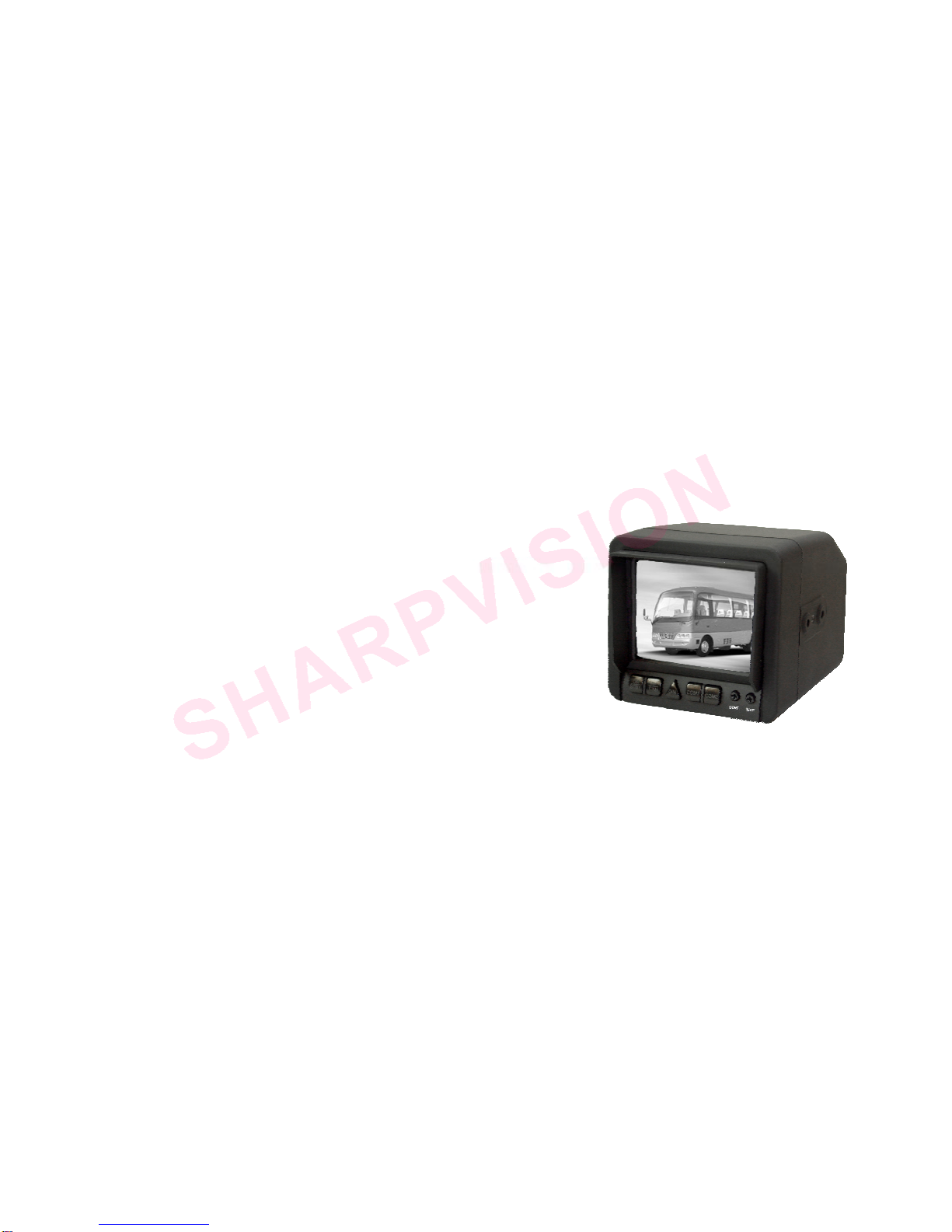
CarRearViewer
OperatingInstruction
Pleasereadthismanualcompletelybeforeoperatingtheunit
SAFETYINFORMATION
Beforeinstallingtheunit,pleasereadalltheCAUTIONSandWARNINGSbelow.
WARNING
Donotexposethemonitororcameratoexcessiveheat,coldormoisture.
Highvoltageiswithinthemonitorandopeningofenclosureisonlyallowedtoprofessionals.
DonotwatchVCDprogramwhiledriving.
Donotplaceheavyobjectoncablesorcoverthemwithrugsorcarpet.
Donotplacecableswheretheycanbepinchedorsteppedon.
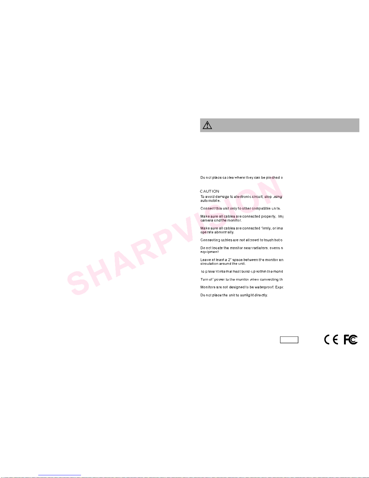
CAUTION
Toavoiddamagetoelectroniccircuit,stopusingthisproductwhiledoingweldingworktothe
automobile.
Neverimmerseanycomponentinwater,anddonotspraycleaning.whencleaning,useadamp
Lint-freeclothonly.
Connectthisunitonlytoothercompatibleunits.
Makesureallcablesareconnectedproperly,Impropercableconnectionsmaydamagethe
cameraandthemonitor.
Makesureallcablesareconnectedfirmly,orimageeffectmaybeworsenedorsystemmay
operateabnormally.
Connectingcablesarenotallowedtotouchhotorrotatingparts,suchasengine,ventilator,etc.
Donotlocatethemonitornearradiators,ovensorotherheatgeneratingappliancesand
equipment.
Leaveatleasta2"spacebetweenthemonitorandwalls,cabinetsorotherobjectstoallowair
circulationaroundtheunit.
Topreventinternalheatbuild-upwithinthemonitor,dontblocktheventilationopenings.
Turnoffpowertothemonitorwhenconnectingthecamera.
Monitorsarenotdesignedtobewaterproof.Exposuretorainorwatermaydamagetheunit.
Donotplacetheunittosunlightdirectly.
i
FDA
e11

TABLEOFCONTENTS
Systemcomposition
Preface
Systeminstallationguide
ii
PREFACE
Thanksforyourpurchasingof
4.5-InchCarRearViewer
SystemFeatures
4.5-inchhighresolutionCRT
Widevoltageinput:DC11V~32V
Built-in2camerasand1VCDvideoswitch
Normal/Mirrorimageswitch
Manual/Autoswitch,systemturnintostandbymodewheninautomobilemode
Camera/VCDinputswitch,compatiblewithreversingandVCDsignal
Camerainputsignalautomaticallyswitchwhenreversing
Videoinput/outputport
Double-sidedPCBboardforefficientlyincreasinganti-vibrationability(8G)
2backgroundcolorofpanelbuttons(blueandred)
Contrastandbrightnessadjustment
Crustmadebyspecialtechnique,withfavorabletouchandtopgradeappearance
Light-touchswitchcontrol
MotormeterlightcontrolLEDtoachievedisplayingstepstatus
Day/Nightlightnessoption
1
Monitormounting(Figuresindications)
Accessoriesinstallation(Figuresindications)
Systemconnectiondisplay
Identifyingtheparts
Technicalspecification
Troubleshooting
Unitcontain..................................................................................................2
Accessories.................................................................................................2
Systemfeatures...........................................................................................1
Mountingmonitor..........................................................................................3
Connectingpowercable................................................................................3
Systemconnecting.......................................................................................3
Mountingthesupport(Fig.1)...........................................................................4
Fixingthemonitor(Fig.2)...............................................................................4
Screenprotectingboardandsunvisorinstallation(Fig.3)..................................5
Systemconnection(Fig.4)..............................................................................6
Frontandrearviewofproduct(Fig.5)..............................................................7
Panelindications(Fig.6)................................................................................8
Technicalspecification..................................................................................9
Troubleshooting..........................................................................................10

Beforeusingtheproduct,pleasemakesurethatthepackageofproductincludesthe
followingitems.
SYSTEMCOMPOSITION
Monitorsupport Angleadjustmentscrew
Powercable
Screenprotectingboard
Supportmountingscrew
Sunvisor
Accessories
2
SYSTEMINSTALLATIONGUIDE
Thismonitorcanbemountedbyembedding,hangingorseatingtoanypositionwhich
issuitabletothedrivertoobservetheimages.
Mountingmonitor
1.Selectapositiontomountthemonitor
2.Wellpositionthemonitorsupport,markthefixingholepositionanddrillfixing
Holes
3.SeeFig.1,Putspringlockwasheronmountingscrewtofixthemonitorsupport
4.ixthemonitortothesupportwith4angleadjustmentscrewsand2
plasticears.
5.SeeFig.3,Installthescreenprotectingboardandsunvisor.
6.Connectoneendofthepowercable(wire)totherightpositiononthe
dashboard.
7.connecttheotherendofthepowercable(plug)tothemonitor
7.SeeFig.4,connectthemonitorandthecamerawiththesystemconnectingcable.
Youcanlinkthemonitorwithchannelsofcameras,1videoinputand1
channelofvideooutput.
(AVsignalcablecanbeselectivepurchase)
SeeFig.2,f
SeeFig.4,
atmost2
WARNING
Electricalshockorfirehazard.Donottrytoservicethisunityourself.Serviceshould
behandledbyqualifiedtechnicians.
3
Connectingpowercable
Systemconnecting
Systemconnectingcable Plasticear
Item Quantity
Monitor 1
Monitorsupport 1
Supportmountingscrew 4
Powercable 1
Sunvisor 1
Screenprotectingboard 1
Angleadjustmentscrew 4
Systemconnectingcable 1
Plasticear 2
Operatinginstruction 1
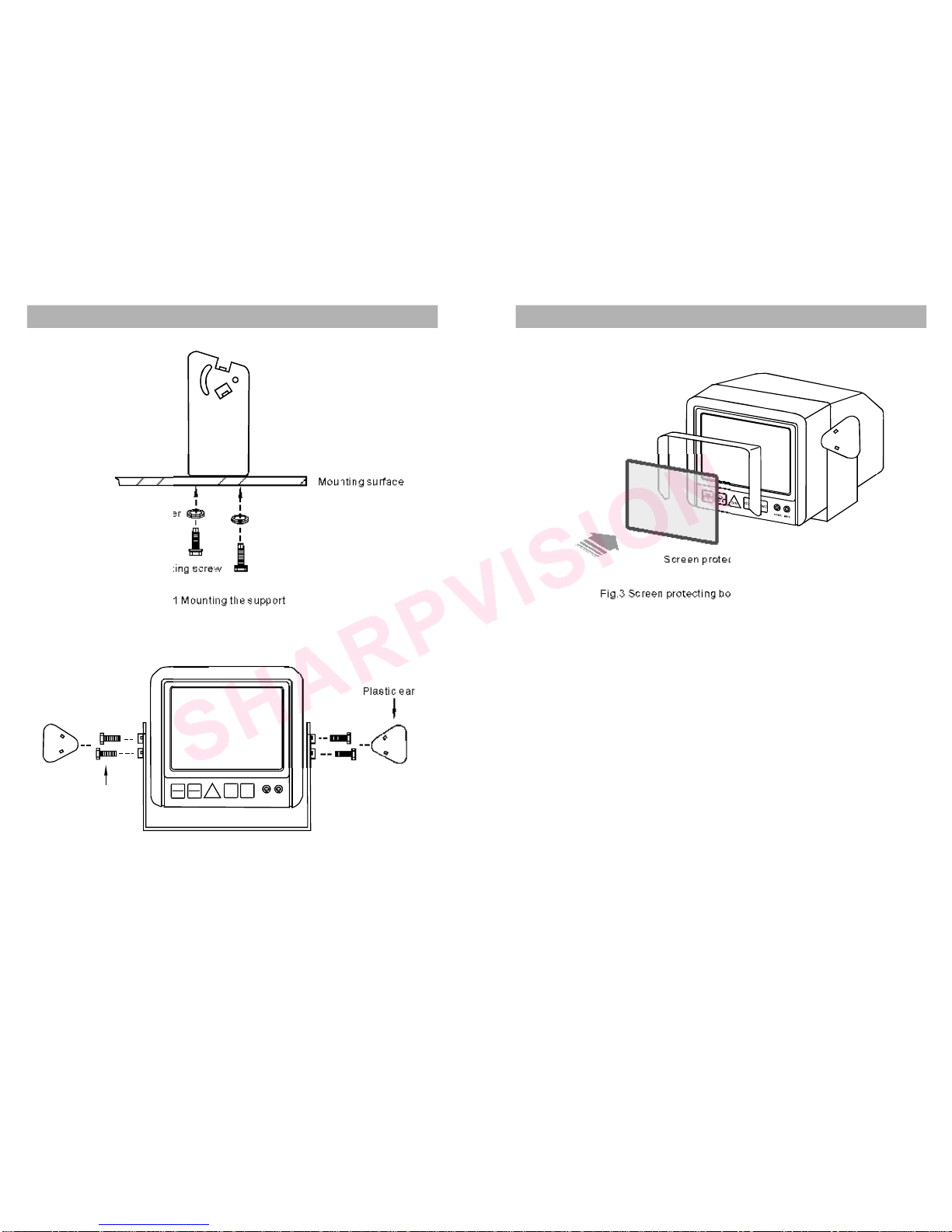
ACCESSORIESINSTALLATION
Fig.3Screenprotectingboardandsunvisorinstallation
MONITORMOUNTING
Monitorsupport
Fig.2Fixingthemonitor
Fig.1Mountingthesupport
Mountingsurface
Supportmountingscrew
Monitorsupport
45
Springlockwasher
CONT. BRIT.
ON
STBY AV
CAM D/N COM1 COM2
Angleadjustment
screw
Plasticear
Sunvisor
Screenprotectingboard
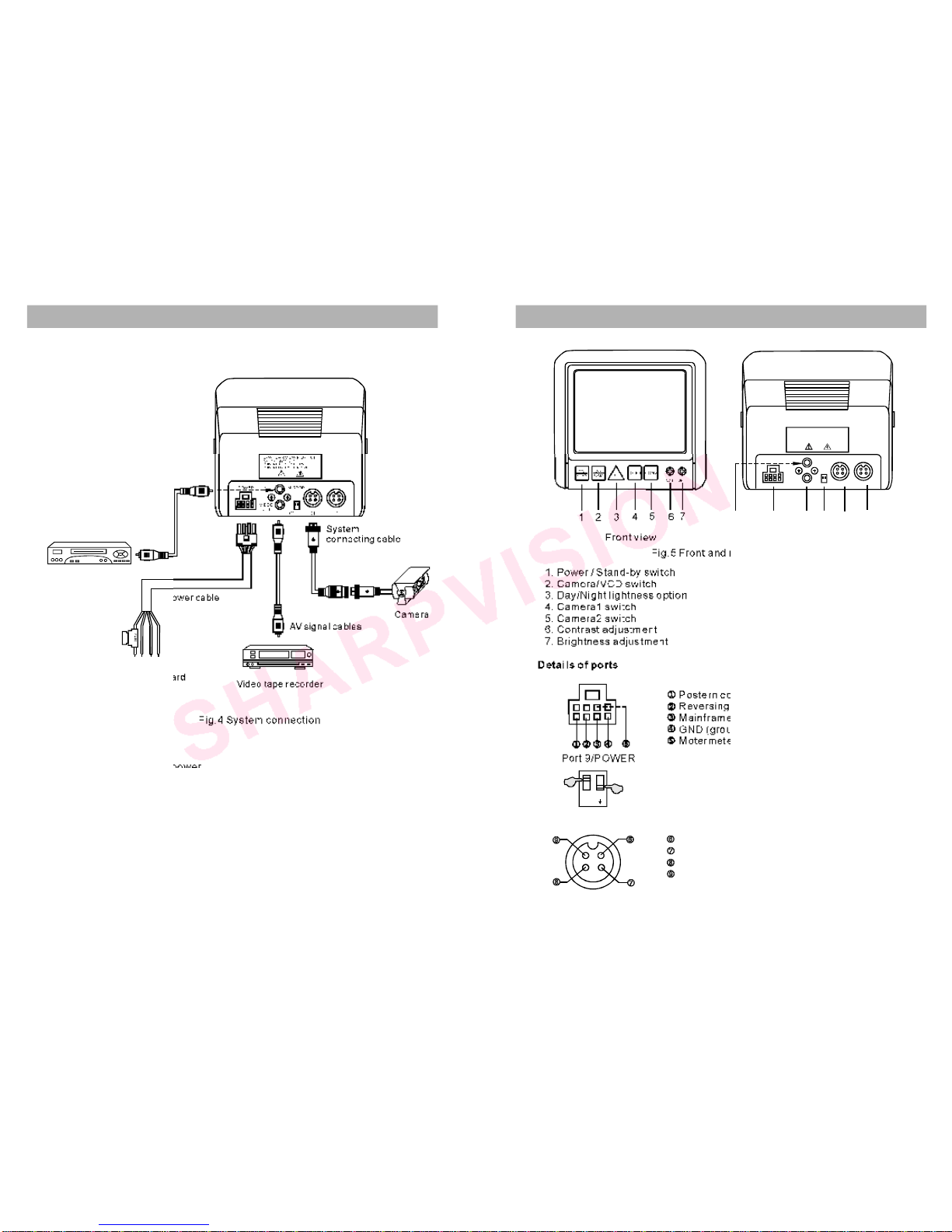
1.Power/Stand-byswitch
2.Camera/VCDswitch
3.
4.Camera1switch
5.Camera2switch
6.Contrastadjustment
7.Brightnessadjustment
Day/Nightlightnessoption
8.Videoinput
9.Powerinput
10.Videooutput
11.Normal/Mirrorimageswitch
12.CamerainputC1
13.CamerainputC2
SYSTEMCONNECTIONDISPLAY
Powercableconnection
1.
2.Browntoreversingcontrolpower
3.
4.Blacktoground(GND)
RedtoDC12Vpowerinput
Whitetoposterncontrolpower
Fig.4Systemconnection
Monitor
Videoplayer
Videotaperecorder
Thisproductcanbelinkedto2channelsofcamerasand1channelofvideoinput
(VCDsignalinput)aswellas1channelofvideooutputwhichconnecttoavideo
taperecorderforrecordingimages.
System
connectingcable Fig.5Frontandrearviewofproduct
6 7
Camera
AVsignalcables
Powercable
1243
B/WREARVIEWMONITOR
CRT:4.5Inch(11.4cm)
POWERINPUT:DC11V~32V
POWERCONSUMPTION:11W
POWER IN
VIDEO
OUT
MIRROR
C1 C2 C1 C2
AVsignalcables
IDENTIFYINGTHEPARTS
CONT. BRIT.
ON
STBY AV
CAM D/N COM1 COM2
B/WREARVIEWMONITOR
CRT:4.5Inch(11.4cm)
POWERINPUT:DC11V~32V
POWERCONSUMPTION:11W
POWER IN
VIDEO
OUT
MIRROR
C1 C2 C1 C2
1 2 3 4567891011 12 13
Posterncontrolpower
Reversingcontrolpower
Mainframepower
GND(ground)
Motermeterlightcontrolpower
Detailsofports
Port9/POWER
Port12/C1
Powerofcamera
GND(ground)
Empty
Videoinput
Mirror Normal
12
ON
Turntheswitchfromuptodowncanswitchtheimage
displayfrommirrortonormal.
Port11/MIRROR
Tocardashboard
Frontview Rearview

TECHNICALSPECIFICATIONS
Thetechnicalspecificationofmonitorislistedbelow
Themanufacturerreservestherighttochangethespecificationswithoutnotice.
NOTICE
8
SerialNo. Item Specifications
1Displaydevice 4.5"CRT(11.4cm)
2Deflectionangle 90
3Inputvoltage 11~32V(DC)
4Outputvoltage 10.2V±0.2V(DC)
5Powerconsumption ≤11W
6Scanningfrequency CCIR:(H)15625Hz/(V)50Hz
EIA:(H)15750Hz/(V)60Hz
7Videoinput 1Vp-p±20%
8Videooutput 1Vp-p±20%
9Horizontalresolution 600TVlinesatmaximum
10 Fieldresolution 400TVlinesatmaximum
11 Anti-vibrationcapability 8G
12 Cameraport DINsocket
13 AVport RCAsocket
14 Operatingtemperature -20 C~+60 C
15 Dimensions 160(W)×127(H)×117(L)mm
(withoutbracket)
16 Weight 3.2kg
IDENTIFYINGTHEPARTS
1 2 34567
CONT. BRIT.
ON
STBY AV
CAM D/N COM1 COM2
1.ON/STBYbutton:Bluelightindicatesstartingup,redlightindicatesmainframe
isinstand-bymode.
2.AV/CAMbutton:Bluelightindicatescamerasignalinput,redlightindicatesVCD
signalinput.
3.D/Nbutton:Bluelightindicatesnightlightmode,redlightindicatesdaylight
mode.
4.COM1button:Bluelightindicatesreversingcamerasignalinput,redlight
indicatesposterncamerainput.
5.COM2button:Bluelightindicatesposterncamerainput,redlightindicates
reversingcamerasignalinput.
6.CONT.button:Toenhancecontrastbyclockwiserotation,todiminishitbyanti-
clockwiserotation.
7.BRIT.button:Toenhancebrightnessbyclockwiserotation,todiminishitbyanti-
clockwiserotation.
Panelinstructions
Fig.6Panelindications
9

TROUBLESHOOTING
Solveproblemsaccordingtothetablebelow
WARNING
Electricalshockorfirehazard.Donottrytoservicethisunityourself.Serviceshould
behandledbyqualifiedtechnicians.
10
Symptom Cause Solution
Rollingimage Monitor(horizontalcontrol) Replacemonitor
Shrunk&Unstableimage Monitorimpropervoltage checkthevoltageofpowersupply
Blackimage Monitorimpropervoltage ifok,checkfuse->checkpowercable,
wiresorconnector(looseorbroken?)
Ifallaboveitemareok,replacemonitor
Whiteimage Monitor/Camera Checkmainsystemcable.Makesure
allconnectorsareconnectedproperly.
Ifok,check4pinDINmonitorcable.Ifok,
replacecamera
Blurredimage Fog,mud,wateroriceon Cleancameraporthole.Ifcondensation
cameralensorporthole ormoistureisvisibleinsidecamera,
moistureincamera initiatedeviceimmediately.
EnginenoiseorStaticlines Monitor Makesuregroundand+12VDCsource
isinsolidconnection.Calltech-support
forassistance
NolightdisplayedonmonitorBrokenfuseorlowbright- Checkwhetherthefuseisbrokenor
nesslevel brightnessadjustmenthasbeenturned
tothelowestlevel
Noimage Improperpluggingin plugtheconnectorproperlyorreplace
connectororbrokensystemthesystemconnectingcable
connectingcable
GuaranteeCard
Thiscardisanimportantevidenceformaintenanceserviceforend-user.
Pleasekeepitproperly.
Forproperoperationundernormalcondition,weprovidethefollowingservices:
1.Replacementwithin3months.
2.Freemaintenanceservicewithin1year.
3.Lifemaintenanceservice(whenguaranteeperiodexpires,materialcostis
needed
Thiscardisinvalidunderthefollowingcondition:
1.Damageoftroubleduetounproveddismantle,refittingorusingpartswhich
donotsatisfythespecificationrequirements.
2.Operationbeyondrequiredcondition.
NameofUser:
ModelNumber:
ProductDescription:
ContactInformationofUser
Address:
PostCode:
Tel:
PurchaseDate:
InvoiceNumber:
NameofDistributor:
DistributorSignandStamphere:
Ifyoustillcannotsolvetheproblems,contactourtech-supportengineerfor
assistance.
Table of contents
Other Sharp Vision Automobile Accessories manuals

Popular Automobile Accessories manuals by other brands

Prorack
Prorack K443 Fitting instructions

Federal Signal Corporation
Federal Signal Corporation RAYDIAN Installation and maintenance instructions

Seat
Seat 6J0 072 500 Fitting instructions

AL-KO
AL-KO MAMMUT manual

Addictive Desert Designs
Addictive Desert Designs Bomber installation instructions

Nav TV
Nav TV Ford 4” UNI-CAM manual


KRAM telecom
KRAM telecom Hi-fi Soft mute Quick start quide

Safe Fleet
Safe Fleet PRIME DESIGN HRR3-E-PM22 Assembly instructions

Dakota Digital
Dakota Digital HLY-3073 manual

TOP VEHICLE TECH
TOP VEHICLE TECH GR4MZ1 installation manual

Hayman Reese
Hayman Reese R2525 quick start guide

Discount Car Stereo
Discount Car Stereo VOL-HF Quick start installation guide