Sharp Vision RM-111 User manual

CarRearViewer
OperatingInstruction
Pleasereadthismanualcompletelybeforeoperatingtheunit
SAFETYINFORMATION
Beforeinstallingtheunit,pleasereadalltheCAUTIONSandWARNINGSbelow.
WARNING
Donotexposethemonitororcameratoexcessiveheat,coldormoisture.
Highvoltageiswithinthemonitorandopeningofenclosureisonlyallowedtoprofessionals.
Donotplaceheavyobjectoncablesorcoverthemwithrugsorcarpet.
Donotplacecableswheretheycanbepinchedorsteppedon.
CAUTION
Toavoiddamagetoelectroniccircuit,stopusingthisproductwhiledoingweldingworktothe
automobile.
Neverimmerseanycomponentinwater,anddonotspraycleaning.whencleaning,useadamp
Lint-freeclothonly.
Connectthisunitonlytoothercompatibleunits.
Makesureallcablesareconnectedproperly,Impropercableconnectionsmaydamagethe
cameraandthemonitor.
Makesureallcablesareconnectedfirmly,orimageeffectmaybeworsenedorsystemmay
operateabnormally.
Connectingcablesarenotallowedtotouchhotorrotatingparts,suchasengine,ventilator,etc.
Donotlocatethemonitornearradiators,ovensorotherheatgeneratingappliancesand
equipment.
Leaveatleasta2"spacebetweenthemonitorandwalls,cabinetsorotherobjectstoallowair
circulationaroundtheunit.
Topreventinternalheatbuild-upwithinthemonitor,dontblocktheventilationopenings.
Turnoffpowertothemonitorwhenconnectingthecamera.
Monitorsarenotdesignedtobewaterproof.Exposuretorainorwatermaydamagetheunit.
Donotplacetheunittosunlightdirectly.
i
FDA
e11
TABLEOFCONTENTS
Systemcomposition
Preface
Systeminstallationguide
ii
PREFACE
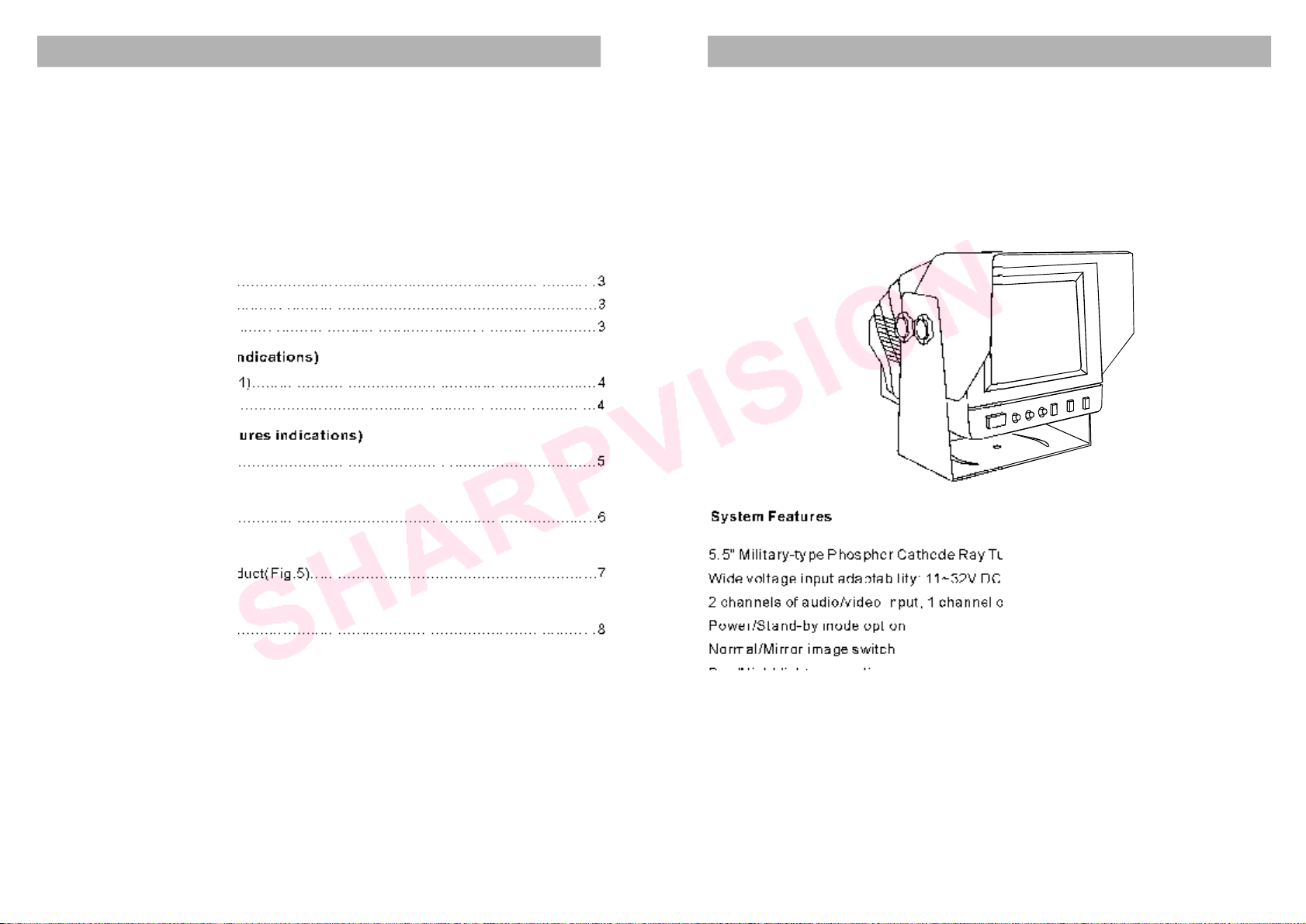
SystemFeatures
5.5"Military-typePhosphorCathodeRayTube(CRT)
Widevoltageinputadaptability:11~32VDC
2channelsofaudio/videoinput,1channelofaudio/videocompositeoutput
Power/Stand-bymodeoption
Normal/Mirrorimageswitch
Day/Nightlightnessoption
NearSunlight-readability
Double-sidedPCBboardforefficientlyincreasinganti-vibrationability(6.8G)
Contrast,brightnessandvolumeadjustment
Built-inspeaker
AdjustableMountingBracket
Sunshieldincluded
1
Monitormounting(Figuresindications)
Portconnectiondisplay(Figuresindications)
Systemconnectiondisplay
Identifyingtheparts
Technicalspecification
Troubleshooting
Unitcontain..................................................................................................2
Accessories.................................................................................................2
Systemfeatures...........................................................................................1
Mountingmonitor..........................................................................................3
Connectingpowercable................................................................................3
Systemconnecting.......................................................................................3
Mountingthesupport(Fig.1)...........................................................................4
Fixingthemonitor(Fig.2)...............................................................................4
Portconnection(Fig.3)...................................................................................5
Systemconnection(Fig.4)..............................................................................6
Frontandrearviewofproduct(Fig.5)..............................................................7
Technicalspecification..................................................................................8
Troubleshooting..........................................................................................9
Thanksforyourpurchasingof
5.5-InchCarRearViewer
Beforeusingtheproduct,pleasemakesurethatthepackageofproductincludesthe
followingitems.
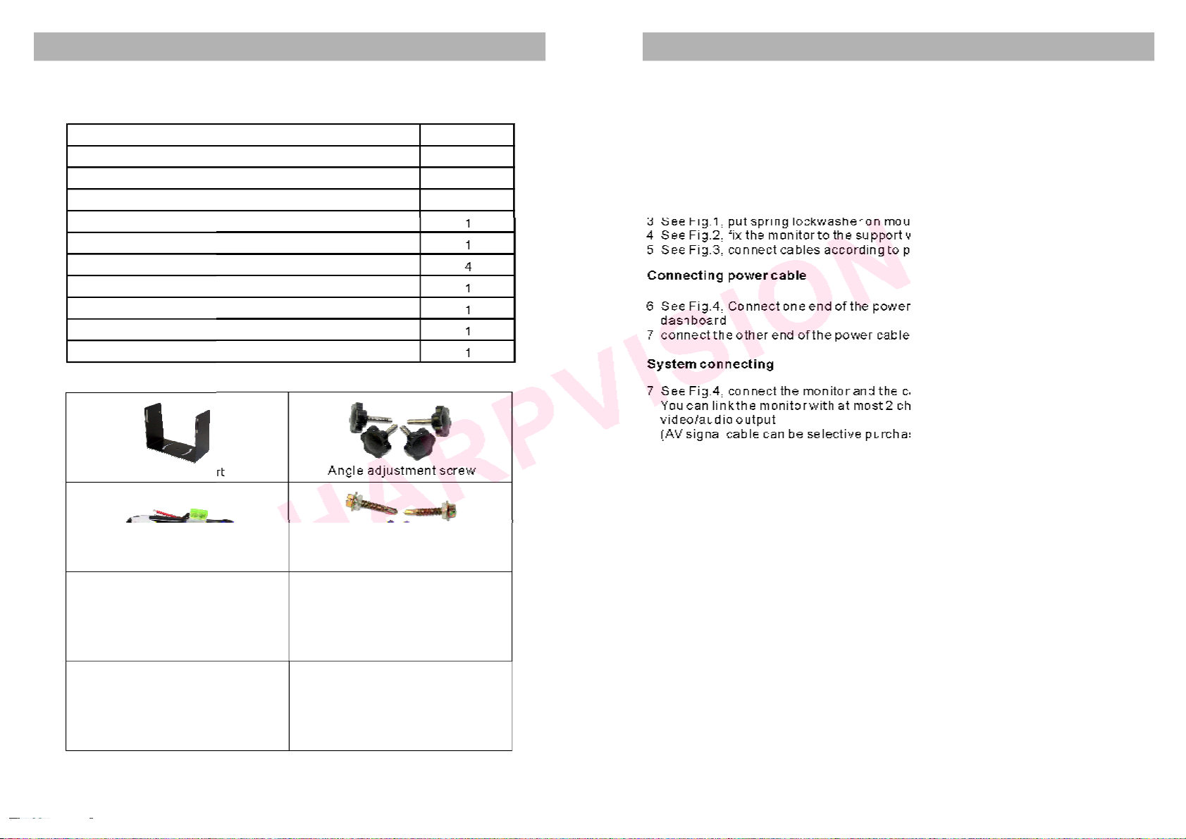
SYSTEMCOMPOSITION
Monitorsupport Angleadjustmentscrew
Powercable
Directionindicationfilm
Supportmountingscrew
Sunshield
Accessories
2
SYSTEMINSTALLATIONGUIDE
Thismonitorcanbemountedbyembeddingtothedasharea,hangingfromthetruck
rooforseatingtoanypositionwhichissuitabletothedrivertoobservetheimages.
WARNING
Electricalshockorfirehazard.Donottrytoservicethisunityourself.Serviceshould
behandledbyqualifiedtechnicians.
3
Systemconnectingcable Anti-vibrationpad
Mountingmonitor
1.Selectapositiontomountthemonitor
2.Wellpositionthemonitorsupport,markthefixingholepositionanddrillfixing
holes
3.SeeFig.1,putspringlockwasheronmountingscrewtofixthemonitorsupport
4.ixthemonitortothesupportwith4angleadjustmentscrews
5.SeeFig.3,connectcablesaccordingtoportconnectiondiagram
6.Connectoneendofthepowercable(wire)totherightpositiononthe
dashboard
7.connecttheotherendofthepowercable(plug)tothemonitor
7.SeeFig.4,connectthemonitorandthecamerawiththesystemconnectingcable.
Youcanlinkthemonitorwithchannelsofcamerasand1channelof
video/audiooutput
(AVsignalcablecanbeselectivepurchase)
SeeFig.2,f
SeeFig.4,
atmost2
Connectingpowercable
Systemconnecting
Item Quantity
Monitor 1
Monitorsupport 1
Supportmountingscrew 4
Powercable 1
Anti-vibrationpad 1
Angleadjustmentscrew 4
Systemconnectingcable 1
Directionindicationfilm 1
Sunshield 1
Operatinginstruction 1

PORTCONNECTIONDISPLAYMONITORMOUNTING
Fig.2Fixingthemonitor
Monitorsupport
4
5
Angleadjustment
screw
Monitorsupport
Fig.1Mountingthesupport
Mountingsurface
Supportmountingscrew
Springlockwasher
Sunshield
Fig.3Portconnection
1
23456 7
1.Videooutput
2.Camera1input
3.Camera2input
4.Audiooutput
5.Toexteriorspeaker
6.Normal/Mirrorimageswitch
7.Powerinput
Blacktoground(GND)
Redtopowersupply
Orangetoreversinglight
Whitetodimmer
Detailofports
Port7/POWER
Port2/C1
GND(ground)
Powerofcamera
Videoinput
Audioinput
Mirror Normal
12
ON
Turntheswitchfromuptodowncanswitchtheimage
displayfrommirrortonormal.
Port6/MIRROR
5

SYSTEMCONNECTIONDISPLAY
Powercableconnection
1.
2.Browntoreversingcontrolpower
3.
4.Blacktoground(GND)
RedtoDC12Vpowerinput
Whitetoposterncontrolpower
Fig.4Systemconnection
Monitor
Videotaperecorder
Thisproductcanbelinkedto2channelsofcamerasand1channelofvideooutput
whichconnecttoavideotaperecorderforrecordingimages.
System
connectingcable
Fig.5Frontandrearviewofproduct
6 7
Camera
Powercable
AVsignalcables
IDENTIFYINGTHEPARTS
Tocardashboard
Frontview Rearview
1234
1 2 345678
9
10
11 12
13
14
15
1.Powerswitch
2.Powerindicator
3.Contrastadjustment
4.Brightnessadjustment
5.Volumeadjustment
6.Camera1switch
7.Camera2switch
8.Day/Nightlightnessoption
9.CamerainputC1
10.CamerainputC2
11.Videooutput
12.Audiooutput
13.Toexteriorspeaker
14.Normal/Mirrorimageswitch
15.Powerinput
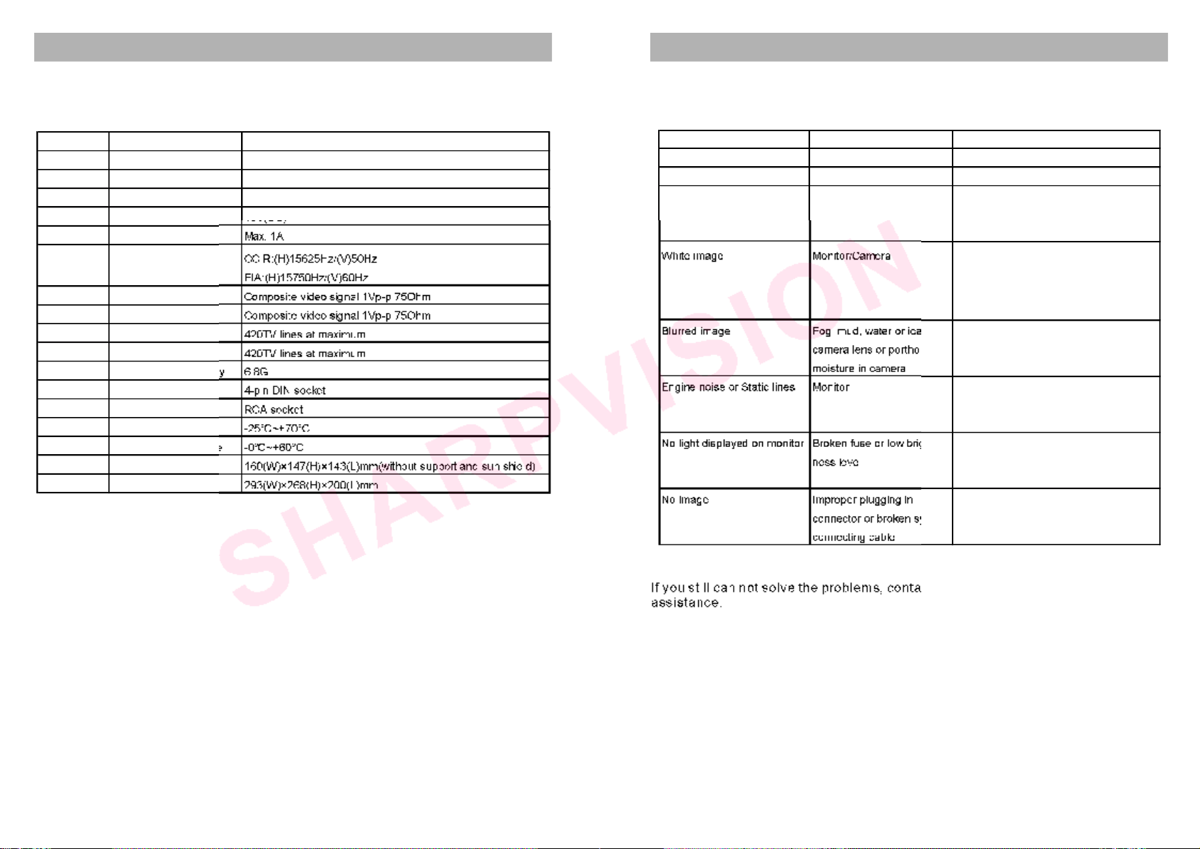
TECHNICALSPECIFICATIONS
Thetechnicalspecificationofmonitorislistedbelow
Themanufacturerreservestherighttochangethespecificationswithoutnotice.
NOTICE
89
TROUBLESHOOTING
Solveproblemsaccordingtothetablebelow
WARNING
Symptom Cause Solution
Rollingimage Monitor(horizontalcontrol) Replacemonitor
Shrunk&Unstableimage Monitorimpropervoltage checkthevoltageofpowersupply
Blackimage Monitorimpropervoltage ifok,checkfuse->checkpowercable,
wiresorconnector(looseorbroken?)
Ifallaboveitemareok,replacemonitor
Whiteimage Monitor/Camera Checkmainsystemcable.Makesure
allconnectorsareconnectedproperly.
Ifok,check4pinDINmonitorcable.Ifok,
replacecamera
Blurredimage Fog,mud,wateroriceon Cleancameraporthole.Ifcondensation
cameralensorporthole ormoistureisvisibleinsidecamera,
moistureincamera initiatedeviceimmediately.
EnginenoiseorStaticlines Monitor Makesuregroundand+12VDCsource
isinsolidconnection.Calltech-support
forassistance
NolightdisplayedonmonitorBrokenfuseorlowbright- Checkwhetherthefuseisbrokenor
nesslevel brightnessadjustmenthasbeenturned
tothelowestlevel
Noimage Improperpluggingin plugtheconnectorproperlyorreplace
connectororbrokensystemthesystemconnectingcable
connectingcable
Ifyoustillcannotsolvetheproblems,contactourtech-supportengineerfor
assistance.
Electricalshockorfirehazard.Donottrytoservicethisunityourself.Serviceshould
behandledbyqualifiedtechnicians.
SerialNo. Item Specifications
1Displaydevice 5.5"CRT
2 Deflectionangle 70
3Inputvoltage 11~32V(DC)
4Outputvoltage 10V(DC)
5Powerconsumption Max.1A
6Scanningfrequency CCIR:(H)15625Hz/(V)50Hz
EIA:(H)15750Hz/(V)60Hz
7Videoinput Compositevideosignal1Vp-p75Ohm
8Videooutput Compositevideosignal1Vp-p75Ohm
9Horizontalresolution 420TVlinesatmaximum
10 Fieldresolution 420TVlinesatmaximum
11 Anti-vibrationcapability 6.8G
12 Cameraport 4-pinDINsocket
13 AVport RCAsocket
14 Sptoragetemperature -25 C~+70 C
15 Operatingtemperature -0 C~+60 C
16 Dimensions 160(W)×147(H)×143(L)mm(withoutsupportandsunshield)
17 Parkingdimensions 293(W)×268(H)×200(L)mm

GuaranteeCard
Thiscardisanimportantevidenceformaintenanceserviceforend-user.
Pleasekeepitproperly.
Forproperoperationundernormalcondition,weprovidethefollowingservices:
1.Replacementwithin3months.
2.Freemaintenanceservicewithin1year.
3.Lifemaintenanceservice(whenguaranteeperiodexpires,materialcostis
needed
Thiscardisinvalidunderthefollowingcondition:
1.Damageoftroubleduetounproveddismantle,refittingorusingpartswhich
donotsatisfythespecificationrequirements.
2.Operationbeyondrequiredcondition.
NameofUser:
ModelNumber:
ProductDescription:
ContactInformationofUser
Address:
PostCode:
Tel:
PurchaseDate:
InvoiceNumber:
NameofDistributor:
DistributorSignandStamphere:
Table of contents
Other Sharp Vision Automobile Accessories manuals

Popular Automobile Accessories manuals by other brands

Whispbar
Whispbar K439W Fitting instructions

V8 equipment
V8 equipment EBEX.2 instruction manual

Volvo
Volvo 240 installation instructions

Classic Accessories
Classic Accessories FAirway Golf Car Seat Cover instructions

AVS
AVS Bugflector installation instructions

Funkwerk
Funkwerk AUDIO 2010 installation instructions


Blaupunkt
Blaupunkt TPMS HN1.0 Operating and installation instructions

FILTRON
FILTRON K 1036 Installation instruction

Rosco
Rosco SAFE -T-SCOPE Installation & user manual

SUPER SEAL
SUPER SEAL Python STR609 owner's manual

Nav TV
Nav TV Ford 4” UNI-CAM manual

ViseeO
ViseeO VK-Q1 Installation instructions & user manual