manuals.online logo
Brands
  1. Home
  2. •
  3. Brands
  4. •
  5. Nav TV
  6. •
  7. Automobile Accessories
  8. •
  9. Nav TV Ford 4” UNI-CAM User manual

Nav TV Ford 4” UNI-CAM User manual

Ford 4” UNI-CAM
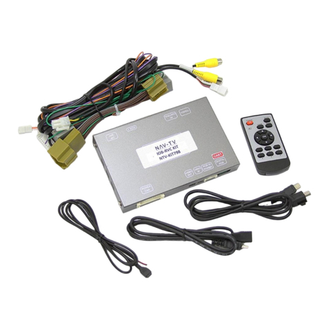
Dual rear-camera integration kit for Ford 4” screens
NTV-KIT600
BHM
05/01/15
NTV-DOC211
3950 NW 120th Ave, Coral Springs, FL 33065 TEL 561-955-9770 FAX 561-955-9760
BHM
05/01/15
NTV-DOC211
Agreement: End user agrees to use this product in compliance with all State and Federal laws. NAV-TV Corp. would not be held liable for misuse of its product.
If you do not agree, please discontinue use immediately and return product to place of purchase. This product is intended for off-road use and passenger
entertainment only.
2 | P a g e
Optional Reverse Cameras
F-Series/Flex CAM
CAM 8
CAM 7
CAM 6
Overview
The Ford 4” UNI-CAM kit interfaces an aftermarket rear camera into Ford vehicles equipped with the OEM 4” media
screen. No dealership programming is required and all connections are made behind the factory screen. This kit is not
currently plug & play.
Kit Contents
Ford 4” UNI-CAM pin out
PIN #
Description
Color
1
12v (+) constant input
Yellow
2
Input 1 (+): force rear camera
Red
3
Input 2 (+): force front camera
Blue
4
Input 3 (+): de-program wire
Pink
6
VIDEO OUT RCA
Yellow
7
RCA Shield
Black
8
CAN HI (Radio Side)
White/Green
9
CAN HI (Car Side)
White/Brown
10
Ground (-)
Black
11
Output 1: ACC (+)
White/Red
12
Output 2: Reverse (+)
White/Blue
13
Output 3: Front CAM power
White/Purple
15
Front RCA Video IN
White
16
Rear RCA Video IN
Red
17
CAN LO (Radio Side)
Green
18
CAN LO (Car Side)
Brown
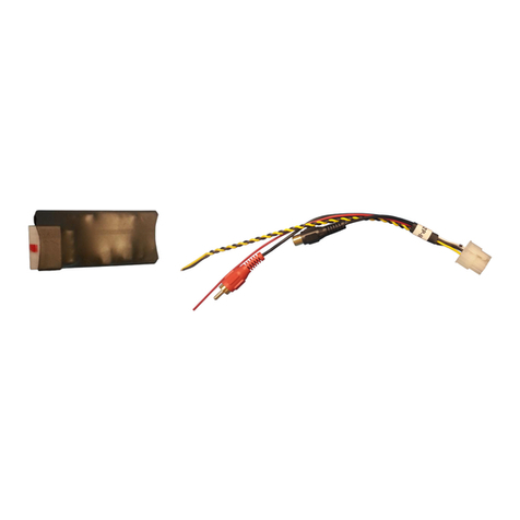
4” UNI-CAM Module
NTV-ASY166
Module Harness
NTV-HAR271
USB Cable
NTV-CAB009
Wire side
Pinned-RCA
NTV-CAB006
Any additional wires not mentioned here are
not used for this install.
BHM
05/01/15
NTV-DOC211
Agreement: End user agrees to use this product in compliance with all State and Federal laws. NAV-TV Corp. would not be held liable for misuse of its product.
If you do not agree, please discontinue use immediately and return product to place of purchase. This product is intended for off-road use and passenger
entertainment only.
3 | P a g e
Module Installation
1. Remove the 4” media screen from the dashboard,
above the CD player.
2. With the 4” screen disconnected and out of the
dash, examine the 12-pin connector that connects
to the screen.
a. Remove the cover by prying with a small
flat/straight pic or similar method.
b. While prying, the cam-lock cover will slide
off.
3. Once the Ford 12-pin plug’s cover has been removed, locate the following wires:
4. Cut the CAN wires (pins 4 & 5) in HALF. Solder CAN in and out wires from the UNI-CAM harness to the
12-pin plug as follows:
5. From the UNI-CAM harness, connect the black wire (pin 10) to ground (pin 11, black/white on the
FORD harness).
6. From the UNI-CAM harness, connect the yellow wire (pin 1) to constant 12v (pin 1, brown/red
on the FORD harness).
7. Use the provided Pinned-RCA cable to populate the connector in the proper location*:
Pin #
Description
Color*
4
CAN HI
Blue/Gray
5
CAN LO
Purple/Gray
1
12v (+) constant
Brown/Red
11
Ground (-)
Black/White
FORD pin #
FORD color
CAN
Direction
UNI-CAM pin #
UNI-CAM color
4
Blue/Gray
HI
Car Side
9
White/Brown
4
Blue/Gray
HI
Screen Side
8
White Green
5
Purple/Gray
LO
Car Side
18
Brown
5
Purple/Gray
LO
Screen Side
17
Green
FORD pin #
Color
Description
6
Blue
RVC Signal
12
Green
RVC Shield
A
B
*Note: Colors may not be consistent for all vehicles,
generally refer to pin numbers instead of colors.
*Note: If the connector already has wires in this location,
remove them and use this RCA instead, or cut the pins off
the RCA and splice into the same location.
BHM
05/01/15
NTV-DOC211
Agreement: End user agrees to use this product in compliance with all State and Federal laws. NAV-TV Corp. would not be held liable for misuse of its product.
If you do not agree, please discontinue use immediately and return product to place of purchase. This product is intended for off-road use and passenger
entertainment only.
4 | P a g e
8. After installing and running your reverse camera to the dash opening, connect your RVC signal to the
connected RCA (from step 6). Power your camera with an ACC source if planning to use the force
camera feature.
9. Optional: if connecting a secondary (front) camera or AUX video source, the RCA connection must be
made differently:
a. Connect the front camera signal to the RCA labeled ‘VIDEO IN’ from the 18-pin UNI-CAM
harness
b. Connect the rear camera signal to the RCA labeled ‘BACKUP CAM’from the 18-pin UNI-CAM
harness
c. Connect the RCA labeled ‘VIDEO TO RADIO’ to the supplied, installed RCA (from step 6) on the
Ford’s 12-pin connector. See diagram for visual aid (page 6).
10. Optional: If adding a secondary (front) camera, connect INPUT 2 (Blue) to 12v through a toggle switch
for activation. Sending 12v (+) to INPUT 2 will force the connected front image at any time.
11. Optional: If the user desires to force the rear camera at any time, connect INPUT 1 (Red) to 12v
through a toggle switch for activation. Sending 12v (+) to INPUT 1 will force the connected rear image
at any time.
12. Connect the UNI-CAM module to the 18-pin harness and proceed to the next section.
Ford 4” UNI-CAM Programming & Testing
Programming for the 4” UNI-CAM is automatic. After all connections are properly made and the module is
connected, turn the car on to IGNITION, wait for the radio to fully boot and settle before testing functionality.
NOTES:
The radio may or may not visually reboot. It may appear that the radio just boots slowly (the first
time, in which case it took programming before the display appeared).
Place the car into reverse, the screen should automatically display the connected reverse image.
This module VIN-LOCKS to the vehicle it is connected to and cannot be used on any other vehicle
until it is De-Programmed. See De-Programming procedure below.
Ford 4” UNI-CAM De-Programming Procedure
Use this procedure if you wish to De-Program the 4” UNI-CAM from the car. This must be completed if you’re
removing the camera from the car, otherwise the screen will show an error while in reverse.
1. Leave the car’s IGNITION in the OFF position.
2. With the module still connected to the vehicle (CAN connections), connect the PINK WIRE (input 3, pin
4) to 12v (+) temporarily.
3. Turn the IGNITION to ON.
4. The radio may or may not visually reboot. It may appear that the radio just boots slowly.
5. Place the car in reverse, confirm that the main radio image remains on the 4” display and does not
show any error.
6. Disconnect the UNI-CAM system entirely, reconnect the previously cut CAN wires and confirm once
more that nothing happens while in reverse.
BHM
05/01/15
NTV-DOC211
Agreement: End user agrees to use this product in compliance with all State and Federal laws. NAV-TV Corp. would not be held liable for misuse of its product.
If you do not agree, please discontinue use immediately and return product to place of purchase. This product is intended for off-road use and passenger
entertainment only.
5 | P a g e
NOTES:
Any wires not shown here
are not needed for this
installation.
Not all wires shown here
will be used for every
installation.
If installing ONLY rear
camera, you may connect
signal directly to the
‘Supplied RCA’
Refer to page
3, step 4 for
specific wiring
instructions
Installation Diagram
Ford 4” UNI-CAM Operation
After all connections are made and programming is complete, placing the vehicle in reverse will
automatically display the connected rear camera’s image.
If forced rear camera is desired, connect input 1 (red) to 12v (+) through a toggle (not included)
and the rear image will show whenever activated.
If a front camera was added, force this camera by connecting input 2 (blue) to 12v (+) through a
toggle (not included).
BHM
05/01/15
NTV-DOC211
Agreement: End user agrees to use this product in compliance with all State and Federal laws. NAV-TV Corp. would not be held liable for misuse of its product.
If you do not agree, please discontinue use immediately and return product to place of purchase. This product is intended for off-road use and passenger
entertainment only.
6 | P a g e

This manual suits for next models

1

Other Nav TV Automobile Accessories manuals

Nav TV RGB-PCM3.1N User manual

Nav TV

Nav TV RGB-PCM3.1N User manual

Nav TV AUDI-P60 User manual

Nav TV

Nav TV AUDI-P60 User manual

Nav TV TOOKI-MB User manual

Nav TV

Nav TV TOOKI-MB User manual

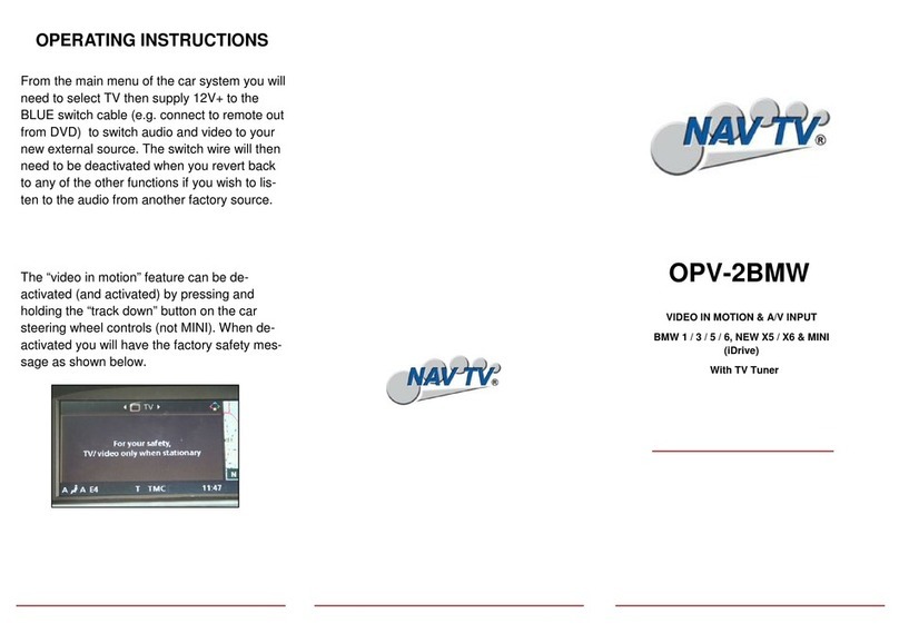
Nav TV OPV-2BMW User manual

Nav TV

Nav TV OPV-2BMW User manual

Nav TV IOB-RVC User manual

Nav TV

Nav TV IOB-RVC User manual

Nav TV CHRY UNI-CAM User manual

Nav TV

Nav TV CHRY UNI-CAM User manual

Nav TV TOYCAM NTV-KIT057 Manual

Nav TV

Nav TV TOYCAM NTV-KIT057 Manual

Nav TV NTV-KIT899 User manual

Nav TV

Nav TV NTV-KIT899 User manual

Nav TV MB25 User manual

Nav TV

Nav TV MB25 User manual

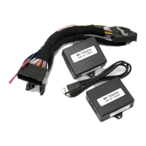
Nav TV MyTouch VIM User manual

Nav TV

Nav TV MyTouch VIM User manual

Nav TV PCM3CAM Manual

Nav TV

Nav TV PCM3CAM Manual

Nav TV MOST-HUR31 User manual

Nav TV

Nav TV MOST-HUR31 User manual

Nav TV PCM3-AV User manual

Nav TV

Nav TV PCM3-AV User manual

Nav TV AUDI-P60H Manual

Nav TV

Nav TV AUDI-P60H Manual

Nav TV Barracuda-CTS Installation and operating instructions

Nav TV

Nav TV Barracuda-CTS Installation and operating instructions

Nav TV MOST-H.U.R. NTV-KIT155 User manual

Nav TV

Nav TV MOST-H.U.R. NTV-KIT155 User manual

Nav TV BMW56-CAN User manual

Nav TV

Nav TV BMW56-CAN User manual

Nav TV AUDI A6 User manual

Nav TV

Nav TV AUDI A6 User manual

Nav TV GM-LVDS User manual

Nav TV

Nav TV GM-LVDS User manual

Nav TV C.O.D-F50 User manual

Nav TV

Nav TV C.O.D-F50 User manual

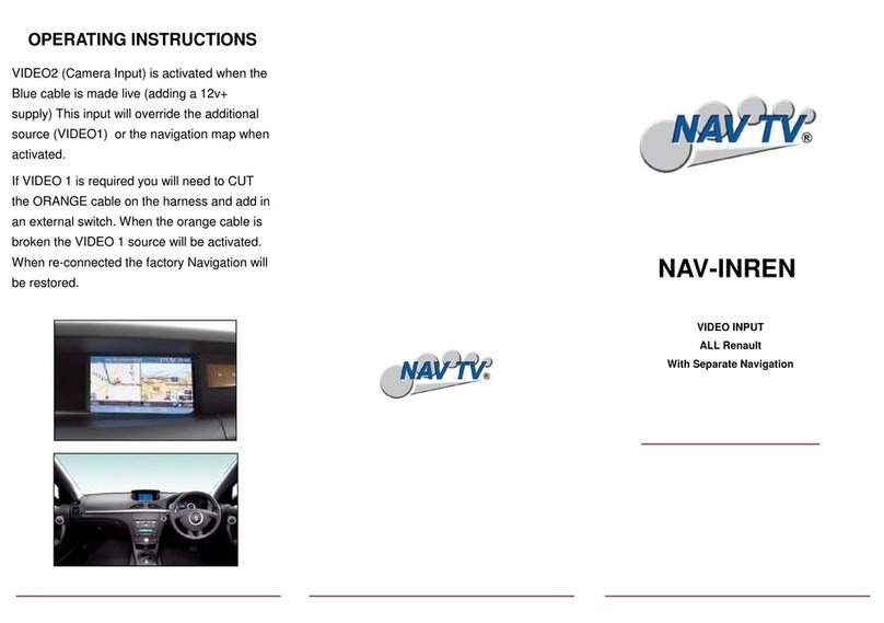
Nav TV NAV-INREN User manual

Nav TV

Nav TV NAV-INREN User manual

Nav TV MY-CUE User manual

Nav TV

Nav TV MY-CUE User manual

Nav TV V2P-II User manual

Nav TV

Nav TV V2P-II User manual

Nav TV ZEN-25 User manual

Nav TV

Nav TV ZEN-25 User manual

Popular Automobile Accessories manuals by other brands

Whelen Engineering Company 600 Series installation guide

Whelen Engineering Company

Whelen Engineering Company 600 Series installation guide

Spyder Auto PRO-YD-C300C-HL installation guide

Spyder Auto

Spyder Auto PRO-YD-C300C-HL installation guide

Prorack K1062 instructions

Prorack

Prorack K1062 instructions

kincrome K12101 manual

kincrome

kincrome K12101 manual

TruckCraft TC-202 owner's manual

TruckCraft

TruckCraft TC-202 owner's manual

Oypla 3665 user manual

Oypla

Oypla 3665 user manual

TRUCKBOSS Flip Extension Install instructions

TRUCKBOSS

TRUCKBOSS Flip Extension Install instructions

Hook BTZ 21-20B manual

Hook

Hook BTZ 21-20B manual

Streetwize SWRB5 Instructions for use

Streetwize

Streetwize SWRB5 Instructions for use

Nielsen CT2345 Original instructions

Nielsen

Nielsen CT2345 Original instructions

Westfalia 96 26 70 manual

Westfalia

Westfalia 96 26 70 manual

wamovo Skylight Mounting instructions

wamovo

wamovo Skylight Mounting instructions

Hunter Quick Check Drive Operation instructions

Hunter

Hunter Quick Check Drive Operation instructions

VW 1K8 071 609 Fitting instructions

VW

VW 1K8 071 609 Fitting instructions

Weh TK16 H2 operating instructions

Weh

Weh TK16 H2 operating instructions

VBG Onspot Mounting instructions

VBG

VBG Onspot Mounting instructions

Honeywell Thor VM1A user guide

Honeywell

Honeywell Thor VM1A user guide

Rola PMX022 quick start guide

Rola

Rola PMX022 quick start guide

manuals.online logo
manuals.online logoBrands
  • About & Mission
  • Contact us
  • Privacy Policy
  • Terms and Conditions

Copyright 2025 Manuals.Online. All Rights Reserved.