-4-
• Apply 12 VDC to the 10GA RED power
lead. One half of the front of the lightbar will light steady to
indicate which configuration is selected (driver side - 12 VDC
activate / passenger side 12 VDC deactivate).
• To change the configuration, momentarily
apply 12 VDC to the Flash Alleys & Takedowns (YEL) control
input. The configuration will switch to the opposite mode, and
the opposite half of the front of the lightbar will light steady.
• The configuration will change each time 12
VDC is momentarily applied to the YEL control input wire.
• When programming is completed, remove
12 VDC from all circuits. Ensure all leads are properly con-
nected and test for proper operation.
b. Intersection Mode.
The Default setting is that Intersection
mode is activated when 12 VDC is applied to the Intersection
(WHT/YEL) control input wire, and deactivated when 12 VDC
is removed from the WHT/YEL control input wire. This con-
figuration can be changed so that Intersection mode is a TAP II
function, where 12 VDC is momentarily applied to the WHT/
YEL control input wire to activate Intersection mode, then 12
VDC is again momentarily applied to the WHT/YEL control
input wire to deactivate. To change the configuration, perform
the following programming steps:
• With all power removed from the 10GA
RED power lead and control input wires, apply 12 VDC to Pro-
gram (WHT/BLK) and Intersection (WHT/YEL) control input
wires.
• Apply 12 VDC to the 10GA RED power
lead. One of the end caps of the lightbar will light steady to
indicate which configuration is selected (passenger side - 12
VDC active / driver side — TAP II).
• To change the configuration, momentarily
apply 12 VDC to the Flash Alleys & Takedowns (YEL) control
input. The configuration will switch to the opposite mode, and
the opposite end cap of the lightbar will light steady.
• The configuration will change each time 12
VDC is momentarily applied to the YEL control input wire.
• When programming is completed, remove
12 VDC from all circuits. Ensure all leads are properly con-
nected and test for proper operation.
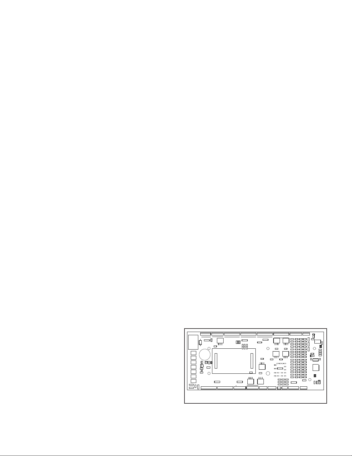
c. Flash Alleys & Takedowns - The Default
setting is that both Alleys & Takedowns flash when 12VDC is
applied to the Flash Alleys & Takedowns (YEL) control input.
This configuration can be changed to Flash Takedowns Only
when 12VDC is applied to the YEL control input . To change
configuration, perform the following programming steps:
• With all power removed from the 10GA
RED power lead and control input wires, apply 12 VDC to the
Program (WHT/BLK) and Flash Alleys & Takedowns (YEL)
control input wires.
• Apply 12 VDC to the 10GA RED power
lead. The driver side end cap will light steady if Flash Alleys
& Takedowns is selected. The front of the lightbar will light
steady if Flash Takedowns Only is selected.
• To change the configuration, momentarily
apply 12 VDC to the Steady Red (ORG) control input wire. The
configuration will switch to the opposite mode, and the alter-
nate indicator will light steady.
• The configuration will change each time 12
VDC is momentarily applied to the ORG control input wire.
• When programming is completed, remove
12 VDC from all circuits. Ensure all leads are properly con-
nected and test for proper operation.
After all programming is completed, insulate or
trim the (WHT/BLK) Program wire and secure it to prevent
accidental pattern changes.
C. Function Activation – SignalMaster.
NOTE
Jumpers are factory installed for External SignalMas-
ter Controller.
Refer to table 1 and figures 1 and 4 for proper connec-
tions.
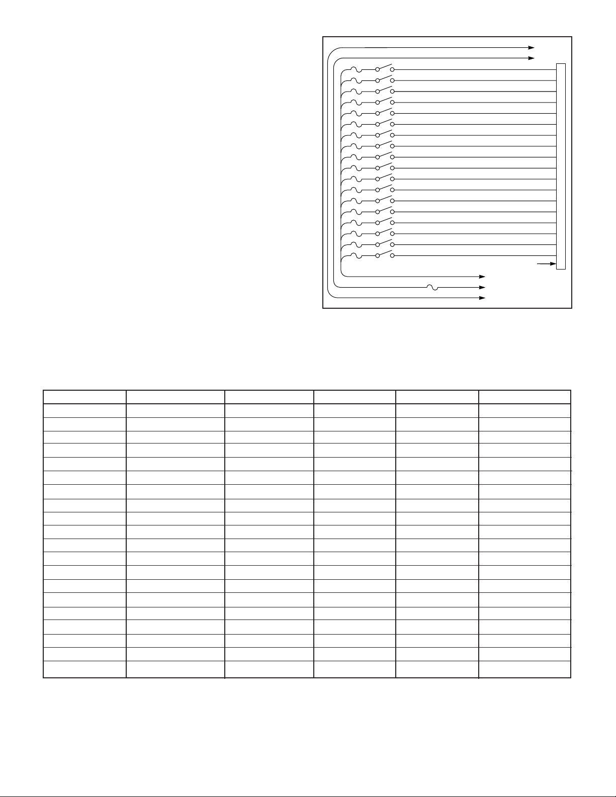
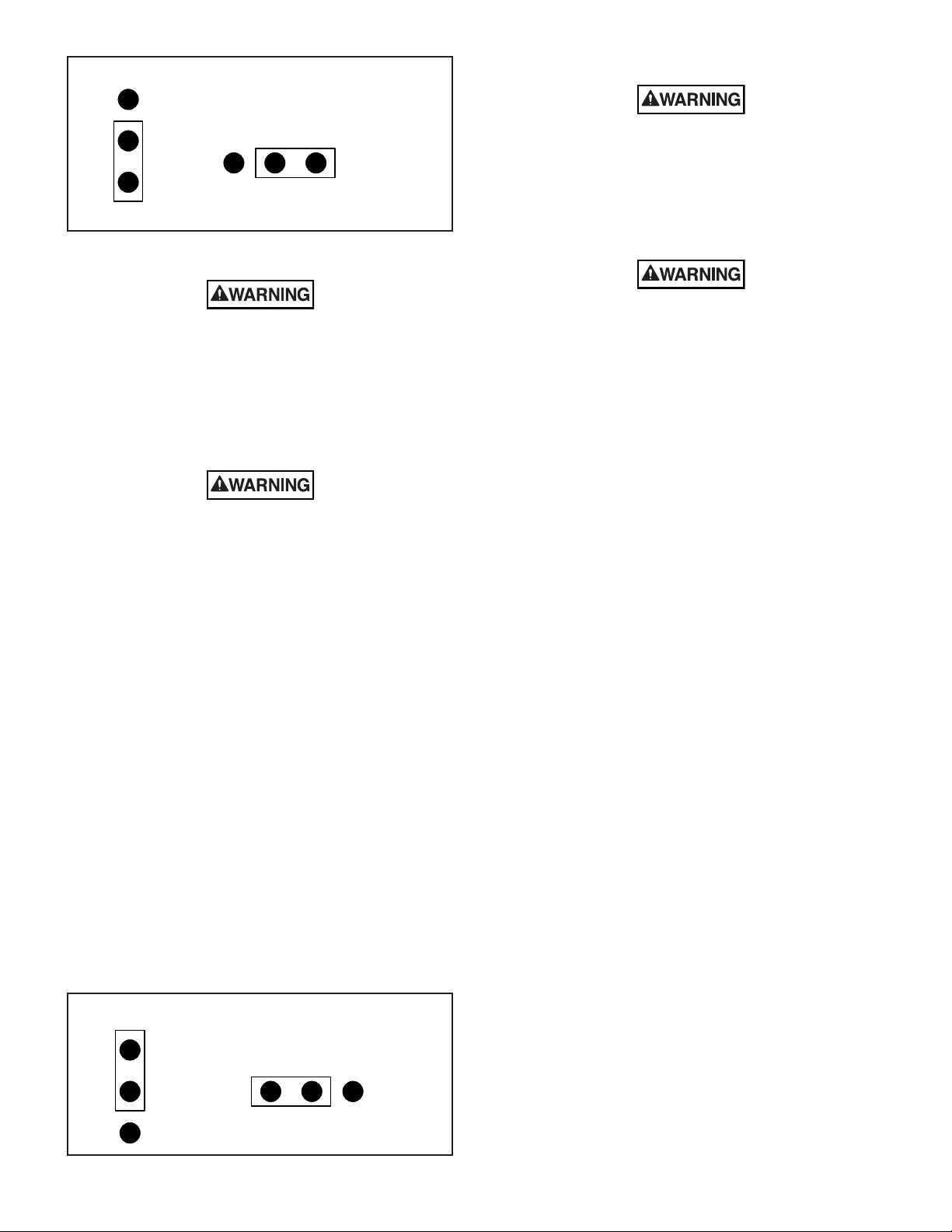
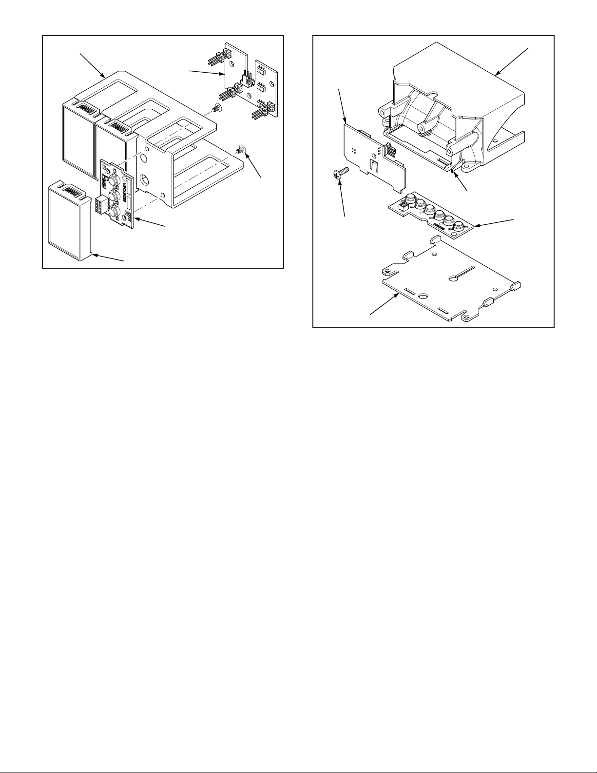
1. SignalMaster Internal Controller.
a. See figure 5. Ensure that jumpers JP2 &
JP7 are installed as indicated
b. When 12VDC is applied to one of the input
wires the corresponding SignalMaster function will activate
(see table 1). The first seven inputs are prioritized, with “Left”
(WHT/BRN) being the highest priority and “Warn 4” (WHT/
GRN) being the lowest priority. The highest priority input
that has 12VDC applied will override any other input that
has 12VDC applied. When using a three position progressive
slide switch for “Left”, “Center” and “Right” functions, “Left” is
connected to position one “Center” to position two and “Right to
position three. The “Fast” (WHT/GRY) input will cause the Sig-
nalMaster to operate at twice the normal speed, when 12VDC
is applied to the input.
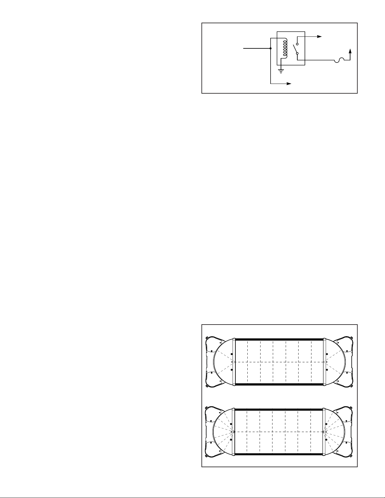
2. SignalMaster External Controller.
a. See figure 6. Ensure that jumpers JP2 &
JP7 are installed as indicated.
b. Refer to table 1 and connect the SignalMas-
ter input wires to the corresponding connections of the Signal-
Master controller.
J17
R30
Q2
+
R40
H3
H2
H4
F7
R55
+ +
Q-
F6
J12
+
P-O- + N-
C28
F5 D10
C33
F4
F3
C20
+
Q6
+D4
+
F2
U5
F1
C21
J10
R41
Q8
-
J13
+
M-L-
U8
+K- + J
J14
GG
HH EFF F HG NM -
U9
UPPER TAKEDOWNS
ALLEY- -
J15
++
Q9
J16
ORG
WHT
+SR -
R46
Q7
J11
R29
Q4
ALLEY
J9
A
+
C10
D2
-
U1
D C B
R6
R15
+
J1
BB CC DD
J2
+
JP4
MADE IN U.S.A.
UNIVERSITY PARK,IL
FEDERAL SIGNAL CORP.
2005245A-
-
J3
JJ
Q1
- - - + - KK +
1 2
JP3
3
R7 R8
LL +MM
- +
R9
NN- + -
GND
LF
H1
NSM
SM
JP5
U2
-
OO
J4
+PP +QQ
- + -
U3
-
J5
+ - LR + -
RF +RR +
R20 R22R19 R21
C49
D21
RSB
R51 R52
J18
C46
SR+ -
J19
C47
C42
D19
D18
C43
D20
R53
SIGMAST INPUTS
FSB
C48
J20
U10
R47
C44
R48
C45
MAIN PROG
J21
R50
JP7
R49
R54
D22
C50
C24
R33R32
D17
D12
D14 D15
D11
D16
U6
D7
D5
D6 D8 D9
C38
R42
C34
D13
R43
C39
C35
R36
C29
R37
C30
R31
R17 R18
C22
C16
C23
C17
R25
C11
R26
C12
R35R34
C37
R45
C41
R44
C40
C36
R39R38
C31 C32
1
U7
R24
D3
C25
C19C18
C26
R28
C14
R27
C13
JP6
Y1
C15
C27
C9
R23
R16
PATTERN INPUTS
J7
RIGHT
ALLEYS
RIGHT
TAKEDOWNS
LEFT
J6
Q3
LEFT
C5
R11
C6
R12
R1
C1
R2
C2
D1
R5
JP1
C8
R14
C7
R13
JP2
SM PROGRAM
R3 R4
C3 C4
J8
C52
C51
U4
R10
290A4745
Figure 4.