Sharp AL-1217 User manual

AL-1217
AL-1457
DIGITAL MULTIFUNCTIONAL SYSTEM
OPERATION MANUAL

CLASS 1 LASER PRODUCT
LASER KLASSE 1
LUKOAN 1 LASERLAITE
KLASS 1 LASERAPPARAT
VAROITUS!
LAITTEEN KÄYTTÄMINEN
MUULLA KUIN TÄSSÄ
KÄYTTÖOHJEESSA MAINITULLA
TAVALLA SAATTAA ALTISTAA
KÄYTTÄJÄN
TURVALLISUUSLUOKAN 1
YLITTÄVÄLLE
NÄKYMÄTTÖMÄLLE
LASERSÄTEILYLLE.
VARNING
OM APPARATEN ANVÄNDS PÅ
ANNAT SÄTT ÄN I DENNA
BRUKSANVISNING
SPECIFICERATS, KAN
ANVÄNDAREN UTSÄTTAS FÖR
OSYNLIG LASERSTRÅLNING,
SOM ÖVERSKRIDER GRÄNSEN
FÖR LASERKLASS 1.
CLASS 1
LASER PRODUCT
LASER KLASSE 1
Caution
This product contains a low power laser
device. To ensure continued safety do not
remove any cover or attempt to gain access
to the inside of the product. Refer all
servicing to qualified personnel.
CAUTION
VORSICHT
ADVARSEL
ADVERSEL
VARNING
VARO!
INVISIBLE LASER RADIATION WHEN OPEN AND INTERLOCKS DEFEATED.
AVOID EXPOSURE TO BEAM.
UNSICHTBARE LASERSTRAHLUNG WENN ABDECKUNG GEÖFFNET UND
SICHERHEITSVERRIEGELUNG ÜBERERÜCKT. NICHT DEM STRAHL AUSSETZEN.
USYNLIG LASERSTRÅLING VED ÅBNING, NÅR SIKKERHEDSAFBRYDERE ER
UDE AF FUNKTION. UNDGA UDSAETTELSE FOR STRÅLING.
USYNLIG LASERSTRÅLING NÅR DEKSEL ÅPNES OG SIKKERHEDSLÅS BRYTES.
UNNGÅ EKSPONERING FOR STRÅLEN.
OSYNLIG LASERSTRÅLNING NÄR DENNA DEL ÄR ÖPPNAD OCH SPÄRRAR ÄR
URKOPPLADE. STRÅLEN ÄR FARLIG. BETRAKTA EJ STRÅLEN.
AVATTAESSA JA SUOJALUKITUS OHITETTAESSA OLET ALTTIINA NÄKYMÄTÖNTÄ
LASERSÄTEILYLLE. ÄLÄ KATSO SÄTEESEEN.
Laserstrahl

1
CAUTIONS
Caution label on the unit
The label ( ) in the fusing area of the unit indicates the following:
: Caution, risk of danger
: Caution, hot surface
Cautions on using
Follow the cautions below when using this unit.
Warning:
• The fusing area is hot. Exercise care in this area when removing misfed paper.
• Do not look directly at the light source. Doing so may damage your eyes.
• Do not switch the unit rapidly on and off. After turning the unit off, wait 10 to 15
seconds before turning it back on.
• Unit power must be turned off before installing any supplies.
Caution:
• Place the unit on a firm, level surface.
• Do not install the unit in a humid or dusty location.
• When the unit is not used for a long time, for example for consecutive holidays,
turn the power switch off and remove the power cord from the outlet.
• When moving the unit, be sure to turn the power switch off and remove the power
cord from the outlet.
• Do not cover the unit with a dust cover, cloth or plastic film while the power is on.
Doing so may prevent heat radiation, damaging the unit.
• Use of controls or adjustments or performance of procedures other than those
specified herein may result in hazardous radiation exposure.
• The socket-outlet shall be installed near the unit and shall be easily accessible.
Important points when selecting an installation site
Do not install your unit in areas that are:
• damp, humid, or very dusty
• exposed to direct sunlight
• poorly ventilated
• subject to extreme temperature or humidity changes, e.g., near an air conditioner
or heater.
Be sure to allow the required space around the
machine for servicing and proper ventilation.
20cm
10cm 10cm

2
Cautions on handling
Be careful in handling the unit as follows to maintain the performance of this unit.
Do not drop the unit, subject it to shock or strike it against any object.
Do not expose the drum cartridge to direct sunlight.
• Doing so will damage the surface (green portion) of the drum cartridge, causing
smudges on copies.
Store spare supplies such as drum cartridges and TD cartridges in a dark
place without removing from the package before use.
• If they are exposed to direct sunlight, smudges on copies may result.
Do not touch the surface (green portion) of the drum cartridge.
• Doing so will damage the surface of the cartridge, causing smudges on copies.
Cautions on laser
Trademark acknowledgements
• Microsoft and Windows are trademarks of Microsoft Corporation in the U.S.A. and
other countries.
• IBM and PC/AT are trademarks of International Business Machines Corporation.
• Adobe and Acrobat are trademarks of Adobe Systems Incorporated.
• All other trademarks and copyrights are the property of their respective owners.
In some areas, the "POWER" switch positions are marked "I" and "O" on the copier
instead of "ON" and "OFF".
The symbol "O" denotes the copier is not completely de-energized but in a stand-by
condition at this "POWER" switch position.
If your copier is so marked, please read "I" for "ON" and "O" for "OFF".
Caution!
For a complete electrical disconnection, pull out the main plug.
The socket-outlet shall be installed near the equipment and shall be easily
accessible.
Wave length 770 nm –795 nm
Pulse times 11.82 µs / 7 mm
Output power 0.17 mW ± 0.01 mW
As an ENERGY STAR®Partner, SHARP has determined that
this product meets the ENERGY STAR®guidelines for energy
efficiency.

3
1
2
4
3
5
6
8
7
9
1INTRODUCTION
USING THE MANUALS.................4
PART NAMES ...............................5
OPERATION PANEL.....................6
2SETTING UP THE UNIT
SETUP PROCEDURE...................7
CHECKING PACKED
COMPONENTS AND
ACCESSORIES.............................8
PREPARING THE UNIT FOR
INSTALLATION.............................8
INSTALLING THE TD
CARTRIDGE................................10
CONNECTING THE POWER
CORD..........................................12
3LOADING PAPER
PAPER.........................................14
LOADING THE PAPER TRAY ....... 15
BYPASS FEED
(including special paper)..............17
4
INSTALLING THE SOFTWARE
SOFTWARE FOR THE SHARP
PERSONAL MFP SERIES ..........19
HARDWARE AND SOFTWARE
REQUIREMENTS........................20
BEFORE INSTALLATION ...........20
INSTALLING THE SOFTWARE..22
INDICATORS ON THE
OPERATION PANEL...................32
USING THE PRINTER MODE.....33
USING THE SCANNER MODE...35
HOW TO USE THE ONLINE
MANUAL......................................43
USING OTHER INSTALLED
DRIVERS.....................................44
CONNECTING THE
INTERFACE CABLE....................45
5MAKING COPIES
COPY FLOW ...............................46
ORIGINAL PLACEMENT.............47
SET THE COPY QUANTITY .......49
EXPOSURE ADJUSTMENT/
PHOTO COPYING.......................49
REDUCTION/ENLARGEMENT/
ZOOM..........................................51
SELECTING THE TRAY
(AL-1457).....................................51
6SPECIAL FUNCTIONS
DESCRIPTION OF SPECIAL
FUNCTIONS................................52
TONER SAVE MODE..................52
USER PROGRAMS.....................53
DISPLAYING TOTAL NUMBER
OF COPIES .................................54
7MAINTENANCE
TD CARTRIDGE
REPLACEMENT..........................55
DRUM CARTRIDGE
REPLACEMENT..........................56
CLEANING THE UNIT.................57
8
TROUBLESHOOTING THE UNIT
TROUBLESHOOTING.................59
STATUS INDICATORS................60
MISFEED REMOVAL ..................61
9APPENDIX
SPECIFICATIONS.......................66
ABOUT SUPPLIES AND
OPTIONS.....................................68
MOVING AND STORING
THE UNIT ....................................69
INDEX..........................................70
SOFTWARE LICENSE................73
CONTENTS

4
This chapter provides basic information for using the unit.
USING THE MANUALS
In addition to this printed manual an online manual is also provided. To get full use of all
features and functions of this product, be sure to familiarise yourself with both manuals.
This printed manual provides all installation and setup instructions as well as instructions
in the use of all copier functions. The online manual contains the following information.
Online manual
Provides you with information on how to specify preferences and troubleshooting. Check
the online manual when you use this unit after all the initial setup is completed.
How to use the online manual
Explains how to use the online manual.
Print
Provides information on how to print a document.
Scan
Explains how to scan using the scanner driver and how to adjust the settings for
the Button Manager.
Troubleshooting
Provides instructions on how to solve driver or software problems.
Conventions used in this manual and online manual
• This operation manual explains the operation of the AL-1217 and AL-1457 models. In
cases where the operation is the same, the AL-1457 is used.
• Illustrations of driver screens and other computer screens show the screens that
appear in Windows XP Home Edition. Some of the names that appear in these
illustrations may differ slightly from the screens that appear in other operating systems.
• This operation manual refers to the Single Pass Feeder as the "SPF".
• In this manual, the following icons are used to provide the user with information
pertinent to the use of the unit.
Warns the user that injury may result if the contents of the warning
are not properly followed.
Cautions the user that damage to the unit or one of its components
may result if the contents of the caution are not properly followed.
Notes provide information relevant to the unit regarding
specifications, functions, performance, operation and such, that
may be useful to the user.
Indicates a letter displayed in the display.
1INTRODUCTION

5
1
PART NAMES
TD cartridge Drum cartridge
SPF (AL-1457)
Original
exit area
Original cover (AL-1217)
2
3
4
1
5
7
68
9
10
11
13
14
15
7
Single bypass
(AL-1217)
Multi-bypass
tray (AL-1457)
Original guide
Original feeder tray
Feeding
roller cover
5
3
12
Interface
USB
interface
Parallel
interface
Original table
Operation panel
Front cover
Paper tray
Side cover
Side cover open button
Bypass paper guides
Paper output tray
Paper output tray extension
Power switch
1
2
3
4
5
6
7
8
9
10
Handle
Power cord socket
Fusing unit release lever
Transfer charger
Charger cleaner
11
12
13
14
15

6
OPERATION PANEL
AL-1457
Exposure mode selector key and
indicators
Use to sequentially select the exposure
modes: AUTO, MANUAL or PHOTO.
Selected mode is shown by a lit
indicator. (p.49)
Light and dark keys and indicators
Use to adjust the MANUAL or PHOTO
exposure level. Selected exposure level is
shown by a lit indicator. (p.49) Use to start
and terminate user program setting. (p.53)
Alarm indicators
Drum replacement required
indicator (p.56)
Misfeed indicator (p.61)
TD cartridge replacement
required indicator (p.55)
SPF indicator (p.48) (AL-1457)
SPF misfeed indicator (p.64) (AL-1457)
Copy ratio selector key and
indicators
Use to sequentially select preset
reduction/enlargement copy ratios.
Selected copy ratio is shown by a lit
indicator. (p.51)
Copy ratio display (%) key (p.51)
Display
Displays the specified copy quantity,
zoom copy ratio, user program code,
and error code.
SCANNER key and indicator
(p.32, p.39)
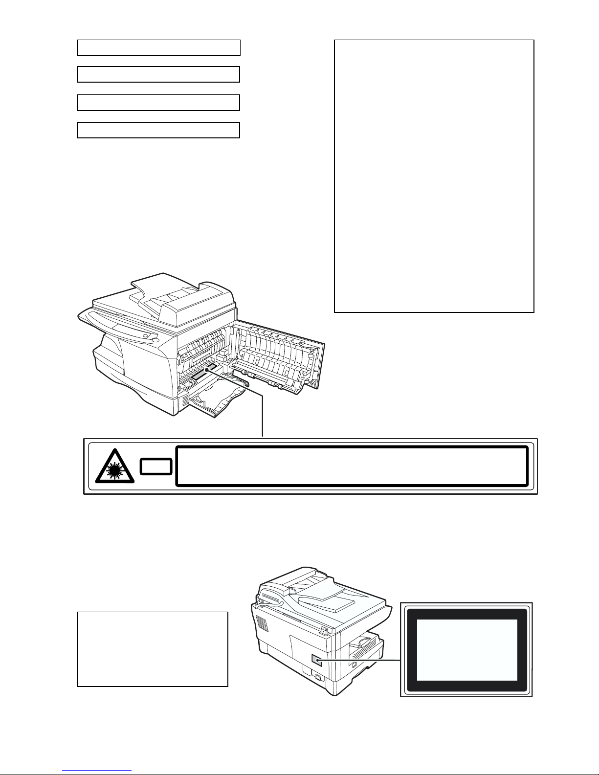
ONLINE key and indicator (p.32)
Lights up when the unit is used as a
printer and scanner. For description of
the ONLINE indicator, see
"INDICATORS ON THE OPERATION
PANEL" (p.32).
1
2
3
4
5
6
7
8
9
10
Power save indicator
Lights up when the unit is in a power
save mode. (p.52, p.53)
Paper feed location indicators
Light up to show the selected paper
feed station.
Tray select key (AL-1457)
Use to select a paper feed station
(paper tray or multi-bypass tray). (p.51)
ZOOM keys and indicator
Use to select any reduction or
enlargement copy ratio from 25% to
400% in 1% increments. (p.51)
Copy quantity keys
• Use to select the desired copy
quantity (1 to 99). (p.49)
• Use to make user program entries.
(p.53)
Clear key
• Press to clear the display, or press
during a copy run to terminate
copying. (p.49)
• Press and hold down during standby
to display the total number of copies
made to date. (p.54)
Start key and indicator
• Copying is possible when the
indicator is on.
• Press to start copying.
• Use to set a user program. (p.53)
11
12
13
14
15
16
17

7
2
Follow the installation procedure below to use the unit properly.
SETUP PROCEDURE
When using the unit for the first time, setup the unit following the procedure shown
below.
*1The multi-bypass tray is only included with the AL-1457.
*2If you are only using the unit for copying, skip this step.
If the unit does not function properly during setup or use, or if a function
cannot be used, see "TROUBLESHOOTING THE UNIT" (p.59).
1 Open the package, and make sure that all the accessories are
supplied with the unit. (p.8)
2 Remove the protective materials. (p.9)
3 Install theTD cartridge. (p.10)
4 Load the paper in the paper tray (p.15) or the multi-bypass
tray*1.(p.17)
5 Connect the power cord
. (p.12)
8 Now, you can copy (p.46), print (p.33), or scan (p.35) your
document.
7 Connect the interface cable*2(p.45) and turn on the unit. (p.12)
6 Install the software.*2(p.19)
2SETTING UP THE UNIT

8
CHECKING PACKED COMPONENTS AND
ACCESSORIES
Open the carton and check if the following components and accessories are
included.
If anything is not included or is damaged, contact your authorised service
representative.
PREPARING THE UNIT FOR INSTALLATION
1Be sure to hold the handles on
both sides of the unit to unpack
the unit and carry it to the
installation location.
Drum cartridge
(installed in unit)
Operation manual
Power cord
Software CD-ROM
TD cartridge

9
2
2Remove all pieces of tape shown in the illustration below. Then
open the original cover/SPF and remove protective materials.
After that, take out the bag containing the power cord and TD
cartridge.
3Release the scan head locking switch.
The scan head locking switch is under the original table.
If the switch is locked ( ), the unit will not operate. Unlock the switch ( )
as shown below.
AL-1217 AL-1457
Lock Unlock
Grasp here and turn in
the direction of the arrow.

10
INSTALLING THE TD CARTRIDGE
1Open the multi-bypass tray
(AL-1457, p.17), and then
open the side cover.
2Remove the CAUTION tape from the front cover and remove the
two protective pins from the fusing unit by pulling the strings
upward one at a time.
3Push gently on both sides of the
front cover to open the cover.
4Remove the TD cartridge from the bag. Remove the protective
paper. Hold the cartridge on both sides and shake it
horizontally four or five times. Hold the tab of the protective
cover and pull the tab to your side to remove the cover.
CAUTION tape
Protective pins
4 or 5 times

11
2
5Gently insert the TD cartridge
until it locks in place while
pushing the lock release button.
6Close the front cover and then
the side cover by pressing the
round projections near the
side cover open button.
When closing the covers, be
sure to close the front cover
securely and then close the
side cover. If the covers are
closed in the wrong order, the
covers may be damaged.

12
CONNECTING THE POWER CORD
1Ensure that the power switch of
the unit is in the OFF position.
Insert the attached power cord
into the power cord socket at the
rear of the unit.
2Plug the other end of the power cord into the nearest outlet.
Power on
Ensure that the power switch of the unit is in the OFF position. Plug the other end of
the power cord into the nearest outlet. Turn the power switch on the left side of the
unit to the "ON" position. The start ( ) indicator will light up and other indicators
which show the initial settings of the operation panel will also light up to indicate the
ready condition. For the initial settings, see the "Initial settings of operation panel"
described on the next page.
If you use the unit in a country other than the country where the unit was
purchased, you will need to make sure that your local power supply is
compatible with your model. If you plug the unit into an incompatible
power supply, irreparable damage to the unit will result.
Only insert the power cord into a properly grounded wall socket.
Do not use extension cords or power strips.
•The unit will enter a power save mode once the set time has elapsed
without any unit operation. The settings of the power save modes can
be modified. See "USER PROGRAMS" (p.53).
•The unit will return to the initial settings a preset amount of time after
the end of copy or scanner job. The preset amount of time (auto clear
time) can be changed. See "USER PROGRAMS" (p.53).

13
2
About the scan head
The scan head lamp remains on constantly when the unit is in the ready condition
(when the start ( ) indicator is illuminated).
The unit adjusts the scan head lamp periodically to maintain copying quality. At this
time, the scan head moves automatically. This is normal and does not indicate unit
trouble.
Initial settings of operation panel
When the unit power is on, the operation panel will revert to the initial settings when
the time set with the "Auto clear time" setting (p.53) elapses after a copy or scanner
job is finished, or when the clear ( ) key is pressed twice.
The initial settings of the operation panel are shown below.
When copying is begun in this state, the settings in the following table are used.
Power off methods
If not used for a certain period of time, the unit will automatically enter auto power
shut-off mode (p.53) in order to minimise power consumption. In cases where the
machine will not be used for a long time, turn off the power switch and remove the
power cord from the outlet.
Copy quantity 1 copy
Exposure adjustment AUTO
Zoom 100%
Tray Paper tray
AL-1457
"0" is displayed in the display.

14
Follow the steps below to load paper into the tray.
PAPER
For best results, use only paper recommended by SHARP.
* Do not use non-standard envelopes, and envelopes that have metal clasps, plastic
snappers, string closures, windows, linings, self-adhesive, patches or synthetic
materials. Do not use envelopes that are filled with air or envelopes that have
labels or stamps attached. These will cause physical damage to the unit.
**For paper weighing from 104g/m2to 128g/m2, A4 is the maximum size that can be
fed through the single bypass or the multi-bypass tray.
• Special papers such as transparency film, labels and envelope must be fed one
sheet at a time through the single bypass or the multi-bypass tray.
Type of paper
feeding
Type of media Size Weight
Paper tray Standard paper A4
A5
B5
Letter
Legal
Invoice
56g/m2to
80g/m2
Single bypass/
Multi-bypass
tray
Standard paper and
thick paper A4
A5
A6
B5
B6
Letter**
Legal
Invoice
52g/m2to
128g/m2**
Special
media Transparency
film A4
Letter
Envelope* International DL
International C5
Commercial 10
Monarch
3LOADING PAPER

15
3
LOADING THE PAPER TRAY
1Raise the handle of the paper tray
and pull the paper tray out until it
stops.
2Remove the pressure plate lock. Rotate the pressure plate lock
in the direction of the arrow to remove it while pressing down
the pressure plate of the paper tray.
3
Store the pressure plate lock which has been removed in step 2.
To store the pressure plate lock, rotate the lock to fix it on the
relevant location.
4Adjust the paper guides on the paper tray to the copy paper
width and length. Squeeze the lever of paper guide and slide
the guide to match with the width of the paper. Move paper
guide to the appropriate slot as marked on the tray.
Pressure plate lock
A
B
Paper
guide B Paper
guide A

16
5Fan the paper and insert it into the tray. Make sure the edges go
under the corner hooks.
6Gently push the paper tray back into the unit.
Do not load paper above the maximum height line ( ). Exceeding
the line will cause a paper misfeed.
•After loading paper, to cancel the blinking without restarting
copying, press the clear ( ) key. The in the display will go out
and the start ( ) indicator will light up.
•Be sure that paper is free of rips, dust, wrinkles, and curled or bent
edges.
•Make sure all the paper in the stack is the same size and type.
•When loading paper, ensure there is no space between the paper and
the guide, and check if the guide is not set too narrow causing the
paper to bend. Loading paper in these ways will result in document
skew or a paper jam.
•When not using the unit for an extended period, remove all paper from
the paper tray and store it in a dry place. If paper is left in the unit for
an extended period, the paper will absorb moisture from the air,
resulting in paper jams.
•When adding new paper to the paper tray, remove the old paper
already contained in the tray. Placing new paper on top of the paper
already contained in the tray may result in feeding two sheets at one
time.

17
3
BYPASS FEED (including special paper)
The multi-bypass tray (AL-1457) or the single bypass (AL-1217) can be used to feed
standard paper, transparency film, labels, envelopes, and other special purpose
paper. Paper measuring from A6 to A4 and in the weight range of 52g/m2to 128g/
m2can be used in this tray. (For paper weighing from 104g/m2to 128g/m2, A4 is the
maximum size.)
The multi-bypass tray (AL-1457)
1Open the multi-bypass tray and extend the tray.
2Set the paper guides to the paper width. Insert the paper (print
face down) all the way into the multi-bypass tray.
•The multi-bypass tray (AL-1457) can hold maximum of 50 sheets of
paper. (Capacity will vary depending on the type of paper loaded.)
The single bypass (AL-1217) can hold one sheet of paper.
•The original image must be smaller than the paper or media for
copying. If the original image is bigger than the paper or media, this
may cause smudges on the edges of the copies.
To close the multi-
bypass tray,
perform step 1
and then step 2 in
the illustration and
push the round
projections at the
right of the tray
until they click.
Print face

18
3Press the tray select ( ) key to select the multi-bypass tray.
The single bypass (AL-1217)
1Select copy settings before you begin the copy job.
For information on the copy settings, see "MAKING COPIES" (p.46)". For
information on the print settings, see the online manual or the Help file for
the printer driver, and then begin printing from the single bypass.
2Set the paper guides to the paper width. Insert a single sheet of
copy or print paper (print face down) into the feed slot of the
single bypass.
Using copy mode
When you insert the paper, the machine will automatically draw in the paper
and begin copying.
Using printer mode
After appears in the
display, wait until the Paper
feed location indicator for the
single bypass illuminates and
insert the paper. The machine
will automatically draw in the
paper and begin printing.
•Paper must be fed narrow side into the feed slot.
•Special papers such as transparency film ,labels and
envelopes must be fed one sheet at a time through the multi-
bypass tray.
•When copying onto transparency film, remove each copy
promptly. Do not let copies stack up.
•If you insert a sheet of paper into the single bypass when multiple
copies have been set with the copy quantity setting (p.49), the copy
quantity setting will change to "0" and only one copy will be made.
•When copying onto transparency film, remove each copy promptly.
Do not let copies stack up.
Note for loading envelopes
• Envelopes must be fed narrow side into the feed slot one at a time.
• Do not use non-standard envelopes, and envelopes that have metal clasps, plastic
snappers, string closures, windows, linings, self-adhesive, patches or synthetic
materials. Do not use envelopes that are filled with air or envelopes that have labels
or stamps attached.
• Envelopes of which the surface is not flat because of embossing may cause the
copies/prints to become smudged.
• Under high humidity and temperature conditions the glue flaps on some envelopes
may become sticky and be sealed closed when copied/printed.
• Use only envelopes which are flat and crisply folded. Curled or poorly formed
envelopes may be poorly copied/printed or may cause misfeeds.
• Be sure to select either Com10, DL, C5 or Monarch on the paper size setting of the
printer driver. (For detailed information on printer driver, refer to the online manual.)
• It is recommended that you perform a test copy/print before performing the actual
copied/printed job.
Print face
This manual suits for next models
1
Table of contents
Other Sharp All In One Printer manuals

Sharp
Sharp MX-C250E Guide

Sharp
Sharp MX-3110N User manual

Sharp
Sharp MX-M950 Quick start guide

Sharp
Sharp DM-2000 User manual

Sharp
Sharp X-M200DK User manual

Sharp
Sharp MX-C528F User manual

Sharp
Sharp MX-5000N User manual

Sharp
Sharp AJ-6010 User manual

Sharp
Sharp AL-1035-WH A Guide

Sharp
Sharp AR-550 User manual

Sharp
Sharp FO-4470 User manual

Sharp
Sharp MX-M260 User manual

Sharp
Sharp MX-M905 Operating instructions

Sharp
Sharp MX-2600N User manual

Sharp
Sharp Advanced MXM365N User manual

Sharp
Sharp AM-400 User manual

Sharp
Sharp MX-2314N User manual

Sharp
Sharp MX-M850 User manual

Sharp
Sharp AR-C360P User manual

Sharp
Sharp CR4 Cloud Series User manual