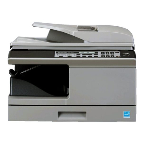
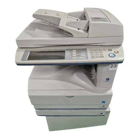
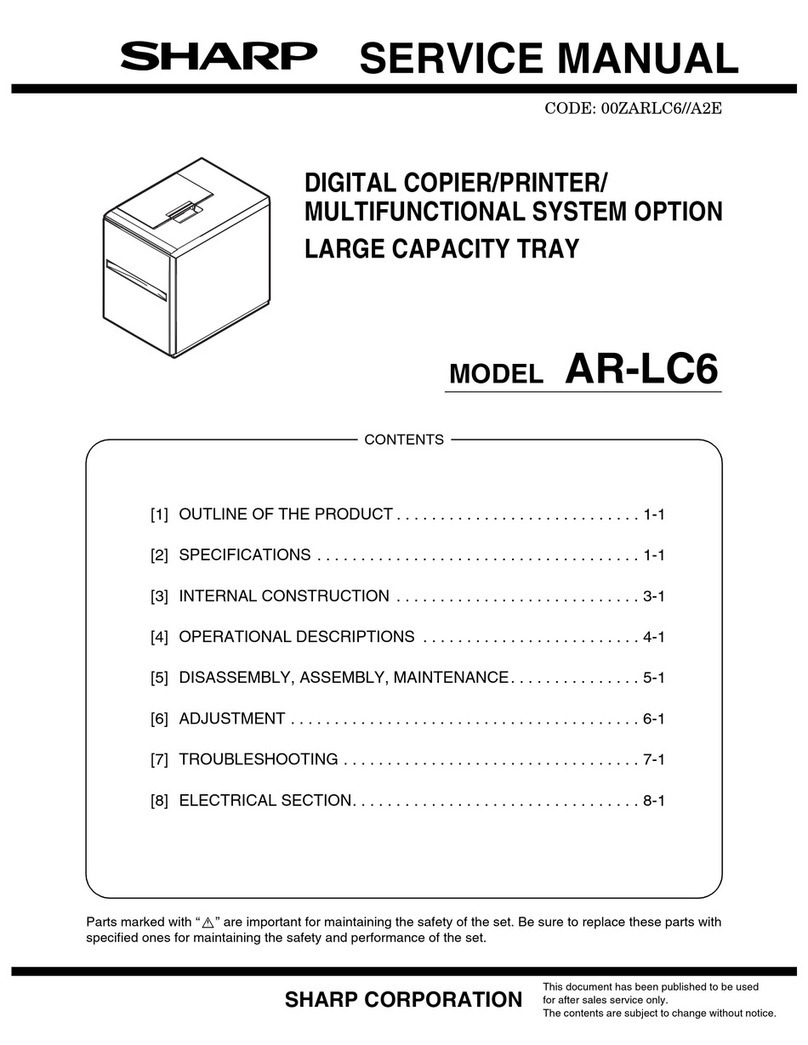
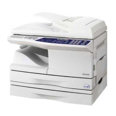
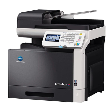
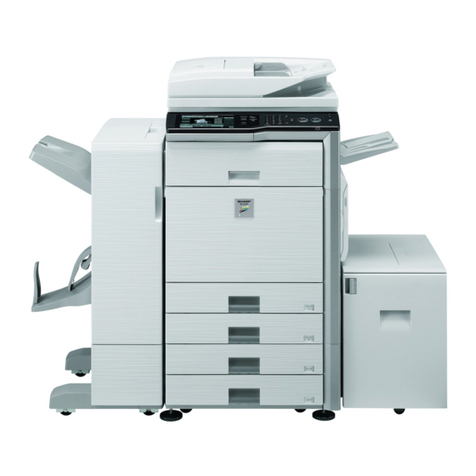
Sharp AL-1552 User manual

CODE : 00Z
qSERVICE MANUAL
CONTENTS
Parts marked with "!" are important for maintaining the safety of the set. Be sure to replace these parts with specified
ones for maintaining the safety and performance of the set.
SHARP CORPORATION This document has been published to be used
for after sales service only.
The contents are subject to change without notice.
AL1553/A1E
DIGITAL MULTIFUNCTIONAL
SYSTEM
AL-1552
MODEL AL-1553
AL-1552
The AL-1552/AL-1553 Service Manual describes only changed from
AL-1217/AL-1457 Service Manual.
For the common contents, please refer to the AL-1217/AL-1457
Service Manual (Code: 00ZAL1457/A1E)
The AL-1552/AL-1553 is a developed from the AL-1217/AL-1457, and
provided with the duplex function.
For the duplex section, refer to the AL-1555 Service Manual and Parts
Guide.
[ 1 ] GENERAL . . . . . . . . . . . . . . . . . . . . . . . . . . . . . . . . . . . . . . . .1 - 1
[ 2 ] SPECIFICATIONS . . . . . . . . . . . . . . . . . . . . . . . . . . . . . . . . . .2 - 1
DParts Guide
Model Reference Model
1 AL-1552 AL-1217
2 AL-1553 AL-1457
3 Duplex AL-1555

AL-1552/AL-1553 GENERAL
1 – 1
[ 1 ] GENERAL
1. MAJOR FUNCTIONS
Configurations
Descriptions of items
F: Standard provision
×: No function or no option available
Item CPM SB/MB 2 Tray SPF R-SPF Color
Scanner GDI
printer PCL
printer SOPM Duplex Memory FAX
Model
AL-1552 15CPM SB ×××FF ×FF
16M ×
AL-1553 15CPM MB ×F×FF ×FF
16M ×
CPM: Copy speed (Copies Per Minute)
SB/MB: SB = Manual feed single bypass, MB = Manual feed multi bypass
2 tray: Second cassette unit.
SPF: Original feed unit
R-SPF: Duplex original feed unit
Color scanner: Color scanner function
GDI printer: GDI printer function with USB.
PCL printer: PCL printer function with USB.
SOPM: Scan Once Print Many function (Many copies are made by one scan.)
Duplex: Auto duplex copy function
Memory: Standard page memory
FAX: FAX function.
AL-1553
AL-1552

AL-1552/AL-1553 DUPLEX-RELATED ITEMS
1 – 2
[ 2 ] DUPLEX-RELATED ITEMS
1. Motors and solenoids
No. Part name Control signal Function/Operation
1 Main motor MM Drives the copier.
2 Scanner motor MRMT Drives the optical mirror base (scanner unit).
3 Toner motor TM Supplies toner.
4 Cooling fan motor VFM Cools the optical section.
5 Resist roller solenoid RRS Resist roller rotation control solenoid
6 Paper feed solenoid CPFS1 Cassette Paper feed solenoid 1
7 Multi paper feed solenoid MPFS Multi manual pages feed solenoid
8 SPF motor SPFM Drives the single pass feeder
9 Duplex motor DMT Devices the duplex paper transport section
10 Original feed solenoid SPUS Original feed solenoid
11 Paper feed solenoid CPFS2 Cassette Paper feed solenoid 2
12 SPF resist roller solenoid SRRS Original resist roller solenoid
13 SPF paper feed solenoid SPFS Original paper feed solenoid
3
9
213
812
10
4
1
5
7
11 6

AL-1552/AL-1553 DUPLEX-RELATED ITEMS
1 – 3
2. Duplex motor section (Duplex model only)
A. Remove the rear cabinet.
1) Remove four screws.
2) Remove the rear cabinet.
B. Remove the main PWB.
1) Disconnect each connector.
2) Remove four screws, and remove the MCU PWB.
3) Disconnect the connector.
4) Remove five screws, and remove the I/F PWB.
C. Remove the Duplex motor.
1) Remove two screws.
2) Remove the Duplex motor cover.
3) Remove the Duplex motor.
Note: When reassembling, be sure to engage the Duplex motor gear
with the belt on the main body side.
3. Reverse roller section (Duplex model only)
A. Remove the reverse unit.
1) Remove four screws.
2) Remove the spring, and the earth wire.
3) Remove the reverse unit.
B. Remove the reverse roller.
1) Bend the reverse roller and remove it.
1)
1)
1)
1)
1)
1)
1)
1)
2)
2)
2)
3) 1)
1)
2)
2)
2)
1
2
3
1
1
2
3
1

AL-1552/AL-1553 DUPLEX-RELATED ITEMS
1 – 4
4. Duplex adjustment
A. Adjusting the paper reverse position in memory
for duplex copying
This step adjusts the front surface printing (odd-number pages of a doc-
ument set) in the S-D mode copying and the leading edge position of an
image on even-number pages in the D-S mode.
That is, it covers the adjustment of the second surface printing mode
(image loss at the front edge of an image) in which image data is once
stored in memory.
The image data is read, starting from its front end in the document deliv-
ery direction (Reference direction of document setting in the OC
mode)and stored in memory.
This stored image data is printed starting at the printing start position, in
the order of last-stored data to the first-stored data.
In other words, the front edge image loss of the image can be adjusted
by changing the document read end position.
(Adjustment procedure)
1) Preparing test chart (Draw a scale at the rear end of one side of a
sheet of A4 white paper or letter paper).
2) Set the test chart so that the scale is positioned as shown below,
in the S-D mode.
3) Execute simulation 50-18 to make a copy and check the front edge
image loss at the area where the scale is printed.
Adjust the setting so that the front edge image loss is less than 4.0
mm in the Duplex mode.
An increase of 1 in setting represents an increase of 0.1 mm
in image loss.
B. Adjusting trailing edge void in duplex copy mode
This is the adjustment of the first surface printing mode (rear end void)
in duplex copying.
In a duplex copying operation, the paper is delivered starting from the
rear end of the first printing surface. It is therefore necessary to make a
void area at the rear end on the first printing surface to prevent paper
jam at the fusing part.
Adjustment modes:
1) Paper trailing edge void quantity 50-19 (TEXT)
This adjustment is made when the cassette paper size is recog-
nized. The trailing edge void quantity can be adjusted by changing
the trailing edge image laser OFF timing.
(Adjustment procedure)
(1) Paper trailing edge void quantity
1) Preparing test chart (Draw a scale at the rear end of one side of a
sheet of A/4 white paper or letter paper)
2) Set the test chart on the document glass as shown below.
3) Using the user simulation [18], set the paper size of the first cassette.
4) Execute simulation 50-19 to turn on the TEXT lamp and make the
printing mode in OC-D mode.
Make a copy of the test chart to check the void area of the scale on
the image.
Adjust the setting so that the void area is 4 - 5 mm. An increase in 1
of setting represents 0.1 mm in void area.
510
Scale (S-D mode)
510
The front edge of the
scale on test chart
Front edge of paper
Void area
less than 4 mm
• Letter paper : 4
• A4 paper : 3
2nd printin
g
surface where scale is printed
(
lower side
)
Document guide The trailing edge has a scale
Table glass
The trailing edge void on the first printing surface is shown above.
Paper
Void position to be check

AL-1552/AL-1553 DUPLEX-RELATED ITEMS
1 – 5
5. List of simulations
Sim
No. Kind of
main code Sub
code Operation
01 Optical system 01
06 Mirror scan operation
Aging of mirror scanning
02 SPF Individual
load operation 02
03
04
SPF sensor status display
Motor ON
Paper feed solenoid ON
05 Lamp ON check 01
02
03
Operation panel display check
Fusing lamp, cooling fan operation check
Copy lamp ON
06 Machine
individual load
operation
01
02 Paper feed solenoid ON
Resist solenoid ON
07 Aging 01
06 Warm-up display and aging with jam
Intermittent aging
08 High voltage
output check 01
02
03
06
Developing bias
Main charger (Grid high)
Grid voltage (Low)
Transfer charger
10 Other None Toner motor aging
14 Trouble reset None Cancel of troubles other than U2
16 U2 trouble reset None Cancel of U2 trouble
22 Counter display 04
05
08
12
14
17
18
19
21
22
JAM total counter display
Total counter display
SPF counter display
Drum counter display
P-ROM version display
Copy counter display
Printer counter display
Scanner mode counter display
Scanner counter display
SPF JAM counter display
24 Special counter
clear 01
04
07
08
09
13
14
15
JAM total counter clear
SPF counter clear
Drum counter clear
Copy counter clear
Printer counter clear
Scanner counter clear
SPF JAM total counter clear
Scanner mode counter clear
25 Main motor ON 01
10
Main motor operation check (Cooling
fan motor rotation check)
Polygon motor ON
26 Various setup 01
02
03
04
06
07
20
30
38
39
40
42
43
44
62
63
Manual feed setup
(R) SPF setup
Second cassette setup
Machine duplex setup
Destination setup
Machine conditions check
Rear edge void setup
CE mark support control ON/OFF
Cancel of stop at drum life over
Memory capacity check
Polygon motor OFF time setup
Time required for turning OFF after
completion of printing)
Transfer ON timing control setup
Side void setup
SPF document rear edge read setup
Energy-save mode copy lamp setup
Fan control select setup
30 Sensor
operation check
(Standard
provision)
01 Paper sensor status display
43 Fusing
temperature
setup
01
04
05
09
Fusing temperature setup (Normal copy)
Fusing temperature setup 2
Fusing temperature setup in duplex
copy
Setup of fusing control of postcard size
paper
46 Exposure
adjustment 01
02
18
19
20
29
31
32
Copy density adjustment (300dpi)
Copy density adjustment (600dpi)
Image contrast adjustment (300dpi)
γtable setup or AE operation mode setup
SPF exposure correction
Image contrast adjustment (600dpi)
Image sharpness adjustment
Copier color reproduction setup
48 Magnification
ratio correction 01 Front/rear (main scanning) direction and
scan (sub scanning) direction
magnification ratio adjustment
49 01 Flash ROM program writing mode
50 Lead edge
adjustment 01
10
18
19
Lead edge image position
Center offset adjustment
Memory reverse position adjustment
in duplex copy
Duplex copy rear edge void adjustment
51 Timing
adjustment 02 Resist quantity adjustment
53 08 SPF scan position automatic adjustment
61 Laser system
operation 03 Polygon motor check
(HSYNC output check)
63 Shading 01 Shading check
64 Self print 01 Self print
Sim
No. Kind of
main code Sub
code Operation

AL-1552/AL-1553 DUPLEX-RELATED ITEMS
1 – 6
6. Contents of simulations
Input method: Clear key 3Exposure Select key 3Clear key 3Exposure Select key
Main
code Sub
code Content
50 18 Memory reverse position adjustment in duplex copy
When this simulation is executed, the current setup value of correction is displayed. Enter the correction value with the 10-key and
press the PRINT switch, and the entered value will be saved. (Correction value 1 ~ 99, correction zero = 0, or 50) When the correc-
tion value is set to 0, the correction value is written as 50.
Front surface printing in the S-D mode and printing on even pages in the D-S mode are reverse memory copy operations from the
document rear edge section.
When, therefore, the output image print position adjustment is required, adjust as follows:
In the reverse memory copy operation, if the document scan direction is in the direction of the arrow in the figure, the scan rear edge
section of the image is printed first.
When, therefore, the print lead edge is shifted, set the reference chart so that the reference position is in the rear edge section, and
use this simulation to adjust so that the print image lead edge comes to the lead edge.
Since printing is performed by processing the scanned image from the scan end position to the scan lead edge, the print lead edge
position adjustment is performed by changing the end data position stored in memory with the simulation setup value.
19 Duplex copy rear edge void adjustment
Used to adjust the rear edge void quantity in duplex copy.
(Operating procedure)
When this simulation is executed, the current setup value is displayed the current setup value is displayed in two digits. (Center
value: 50 However, setup 50 = setup 0) When the correction value is set to 0, the correction value is written as 50. Press the copy
mode select key to select your desired copy mode, and the display will change. Enter the adjustment value with the 10-key and press
the PRINT switch, and the setup value will be saved and a copy will be made. (The paper information is cleared for every copying.)
Press the clear key to save the setup value and exit from the simulation mode. (Increasing the setup value by 1 increases the void
quantity by about 0.1mm.)
Print lead edge
Lead edge void (1)
Print start position
Rear edge void
Print rear edge
Document transport direction
Scan lead edge
Scan end position
(Default: Scan cut by void (1))
Scan direction
Scan rear edge
Paper transport direction
Adjustment mode Lamp ON
Paper rear edge void quantity TEXT lamp
Print start position (Duplex back) PHOTO lamp

– 1 –
MEMO

qPARTS GUIDE
CONTENTS
SHARP CORPORATION
This document has been published to be used for
after sales service only.
The contents are subject to change without notice.
CODE:00ZAL1553/P1E
DIGITAL
MULTIFUNCTIONAL
SYSTEM
AL-1552
MODEL AL-1553
(For Europe)
(AL-1553)
1Exteriors
2Original cover unit(AL-1552)
3SPF exteriors (AL-1553)
4SPF transport unit (AL-1553)
5SPF pick up unit (AL-1553)
6Operation panel
7Side door unit
8Optical frame
9LSU unit
FDelivery paper guide unit
GMiddle frame
HBase plate unit 1
IBase plate unit 2
J Fusing unit
K Drive unit
L Single manual paper feeding cover unit
(AL-1552)
M Multi manual paper feeding cover unit
(AL-1553)
N Single manual paper feeding unit
(AL-1552)
O Multi manual paper feeding unit
(AL-1553)
P Socket holder unit
Q TC case unit
R
250 sheets tray
SHarness
TPacking material & accessories
UOperation PWB
VMCU PWB
WIF PWB
XDC power supply PWB
■Index

– 1 –
DEFINITION
The definition of each Rank is as follows and also noted in the list
Rank A : Maintenance parts, and consumable parts which are not included in but closely related to maintenance parts
Rank B : Performance/function parts (sensors, clutches, and other electrical parts), consumable parts
Rank E : Unit parts including PWB
Rank D : Preparation parts (External fitting, packing, parts packed together)
Rank C : Parts other than the above (excluding sub components of PWB)
Because parts marked with "!" is indispensable for the machine safety maintenance and operation, it must be replaced with
the parts specific to the product specification.
FOther than this Parts Guide, please refer to documents Service Manual(including Circuit Diagram)of this model.
FPlease use the 13 digit code described in the right hand corner of front cover of the document, when you place an order.
FFor U.S. only-Use order codes provided in advertising literature. Do not order from parts department.
*These parts are supplied by SMF.
1Exteriors
NO. PARTS CODE PRICE
RANK
NEW
MARK
PART
RANK DESCRIPTION
1CCAB-0003QS22 AS D Front cover
2LSOU-0001QSJZ AY D Delivery tray
3XEBS730P08000 AC C Screw(3×8)
4LSOU-0008QSJZ AH D Extension tray
5XEBS740P12000 AA N C Screw(4×12)
6PTPE-0041QSZZ AB C Glass fixing tape B
7DHAI-0285QSZZ AK C OP-MCU harness
8PSHEZ0369QSZZ AE C Shading sheet
9XBBS730P08000 AA N C Screw(3×8)
10 GCAB-0061QSZ1 AK D Left cabinet
11 TLABH0387TSZZ ∗NDOperation instruction label
12 GCOV-0045QSZ7 AK N D Rear cover OC (AL-1552)
GCOV-0045QSZ6 AK N D Rear cover SPF (AL-1553)
13 C IX-0021QS11 AH D Glass fixing plate
14 PGLSP0007QSZZ AV B Table glass
15 PTPE-0059QSZZ AC C Glass fixing tape A
16 PCOVP0040QSJZ AL D Rear cabinet cover SPF (AL-1553)
17 GCAB-0062QSZ3 AL D Right cabinet OC (AL-1552)
GCAB-0062QSZ2 AN D Right cabinet (AL-1553)
18 GCAB-0004QSJ1 AX D Rear cabinet (AL-1552)
GCAB-0026QSJ2 AZ D Rear cabinet SPF (AL-1553)
20 PMLT-0024QSZZ AC C Fan cushion
21 P ILZ0002QSZZ AL B Ozone filter
22 PTPE-0044QSZZ AC C Slit glass tape (AL-1553)
23 PGLSP0008QSZZ AH B SPF glass (AL-1553)
24 PSHEZ0181QSJZ AC C Rear cabinet sheet (AL-1553)
25 PTPE-0010QSZZ AC C Slit glass tape (AL-1553)
26 TLABZ0531TSZZ ∗NDClass 1 & cautions label
27 PMLT-0069QSZZ AA C Ground cushion (AL-1553)
28 PSHEZ0404QSZZ AF C Right cabinet ground sheet (AL-1553)
29 PTPE-0047QSZZ AC C Ground tape F (AL-1553)
30 PTPE-0048QSZZ AA C Ground tape R (AL-1553)
31 PTPE-0049QSZZ AC C Right cabinet ground tape (AL-1553)
32 PTPE-0060QSZZ AC C Glass aluminum tape
33 PGSK-0034QSZZ AE C Gasket
–2 –
1Exteriors
2Original cover unit(AL-1552)
NO. PARTS CODE PRICE
RANK
NEW
MARK
PART
RANK DESCRIPTION
1GCOVH0003QSJZ AL D OC cover S
2GCOVH0004QSJ1 AX D OC cover M
3PCUSS0024QSZZ AV D OC mat
(Unit)
901 CCOVH0004RS54 BF E OC cover unit
1
2
3
4
18
9
9
16
21
20
AL-1553
5
5
9
11
9
10
12
7
24 26
PRP02507
17
AL-1552
25
AL-1553
9
29
17
9
22
23
30
27
27
31
18
AL-1552
26
21
20
9
9
28
13 15
8
6
32
33
33
14
1
2
3
PRP02508

–3 –
3SPF exteriors (AL-1553)
NO. PARTS CODE PRICE
RANK
NEW
MARK
PART
RANK DESCRIPTION
1LSOU-0035QSZZ AR D Original tray
2LPLTP0011QSJ2 AH C Control plate F
3LPLTP0012QSJ2 AH C Control plate R
4NGERR0377 CZZ AD C Manual feeding rack gear
5XEPS730P08X00 AA N C Screw(3×8X)
6NGERH0193 CZZ AB C Manual feeding gear
7MSPRP0059QSZZ AD C Control plate spring
11 C RM-0011RS58 BF E SPF pick-up unit
13 XEBS740P10000 AA N C Screw(4×10)
14 C RM-0013RS59 BM E SPF transport unit
15 LBNDJ0013 CZ1 AE C Wire band
16 PSHEZ0384QSZZ AD C Base tray sheet
17 PSHEP0063QSZZ AC C Transport sheet
18 MSPRP0113QSZ1 AD C Earth spring
19 PSHEZ0379QSZZ AD C OC sheet
20 XEBS730P08000 AC C Screw(3×8)
21 MHNG-0017QSZZ AQ C SPF hinge
22 XEBS740P14000 AB N C Screw(4×14)
23 NROLP0011QSZZ AD C Delivery roller
24 PSPO-0001QSZZ AB C Cushion
25 NS TZ0010QSZZ AE C Delivery shaft
26 MSPRT0061QSZZ AC C Delivery spring
27 MSPRP0060QSZZ AD C Transport spring
28 NROLP0010QSZZ AD C Transport roller
29 NS TZ0009QSZZ AE C Transport shaft
30 LPLTM0096QSZ1 AF C Base tray reinforce plate
31 LX-BZ0016QSZZ AC C Screw(3×8)
33 LSOU-0005QSJ4 BA D Base tray
34 PCUSS0025QSZ1 AQ D OC mat
35 PSHEZ0102QSZZ AD C Motor pressure sheet
36 PSHEZ0112QSZZ AE C Delivery earth sheet SPF
37 MSPRC0149QSZZ AC C PS earth spring SPF
38 PSHEZ0386QSZZ AB D Rear side sheet A
39 PSHEZ0387QSZZ AB D Rear side sheet B
40 PSHEZ0388QSZZ AD C OC mat sheet 2
45 PSHEZ0383QSZZ AC C Book detect sheet
501 CSOU-0035RS51 AZ E SPF original tray unit
39
38
39
45
1
2
3
4
5
6
7
15
16
18 40
31
21
22 23
24
25
26 27
28
29
30 31
21
33
13
13
22
13
4
17
17
24
23
28
20
31
31
31
19
22
20
27
20
34
PRP02509
11
501
14
22
13
36
37
35

–4 –
4SPF transport unit (AL-1553)
NO. PARTS CODE PRICE
RANK
NEW
MARK
PART
RANK DESCRIPTION
1PGIDM0042QSJZ AL C U-turn paper guide
2XEBS730P12000 AC C Screw(3×12)
3LX-BZ0012QSZZ AC C Screw
4NGERH0972 CZZ AB C Gear(27T)
5MARMP0001QSZZ AF C Drive arm
6XBPS730P05K00 AA N C Screw(3×5K)
7RMOTP0013QSZZ BB B SPF motor
9DHAI-0290QSZ1 AN C SPF interface harness
10 LBNDJ0013 CZ1 AE C Wire band
11 MSPRT0064QSZ1 AC C Drive arm spring
12 L RM-0013QSZZ AG D Drive frame
13 XRESP50-06000 AA C E-ring(E5)
14 PSHEP3029 CZZ AA C Flange sheet DUP2
15 NBLTT0046QSZZ AE B Belt(83MXL4.8)
16 NGERH0047QSZZ AF C Gear(48T/15T)
17 LPINS0019QSZZ AA C Spring pin(φ2.5-9)
18 NBRGC0017QSZZ AC C Bearing
19 NBRGM0501 CZZ AB C Metal D
20 L RM-0012QSZZ AD D Frame R
21 PSHEZ0445QSZZ AC C Separation sheet
22 LPLTP0013QSZ1 AC C Plate
23 MSPRC0062QSZZ AC C Pressure spring
24 MSPRP0065QSZZ AD C Open and shut lock spring
25 PSHEZ2174 CZZ AB C Paper feeding sheet
26 NPLYZ0146 CZZ AB C 22MXL pulley
27 NBLTT0003QSZ1 AF B Belt(B75MXL4.8)
28 JKNBZ0004QSZZ AD C JAM release knob
29 MSPRC0063QSZZ AB C Delivery paper guide spring
30 PGIDM0024QSZ3 AN C Transport paper guide
31 RDTCT0004QSZZ AL B Inlet detect sensor
32 NROLM0023QSZ1 AP C Delivery roller
33 PBRSR0003QSZ2 AG B Discharger brush
34 PGIDH0029QSZ1 AL C Delivery paper guide
35 PSHEP0044QSZZ AF C White sheet
36 NROLM0022QSZ1 AL C PS roller
37 PCOVP0037QSJZ AH D Front cover
38 PCOVP0038QSJ1 AL D Rear cover
39 XEBS730P10000 AC C Screw(3×10)
40 CPLTM0298QS01 AF C SPF tension plate
41 MSPRT0294QSZZ AC C SPF tension spring
(Unit)
901 C RM-0013RS59 BM E SPF transport unit
27
28
41
26
13
39
13
40
13
13
1
23
4
5
6
7
9
10
11
12
13
14
15
16
17
18
19
20
21
22
23
24
25
26
29
30 31
32
33
34
35
36
2
2
17
17
24
19
13
19
PRP02510
37
38
39
39
29
4
SPF transport unit (AL-1553)

–5 –
5SPF pick up unit (AL-1553)
NO. PARTS CODE PRICE
RANK
NEW
MARK
PART
RANK DESCRIPTION
1GCAB-0008QSJZ AM D Open and shut cabinet
2PSPO-0002QSZZ AC C Stopper cushion
4MARMP0003QSZ1 AD C Stopper arm
5LSTPP0001QSZ1 AD C Paper stopper R
6XEBS730P08000 AC C Screw(3×8)
7CPWB 0155QSE1 AM E SPF sensor PWB
8DHAI-0293QSZZ AE C Sensor harness
9MLEVP0009QSZZ AD C Set detect lever ACT
10 MLEVP0010QSZZ AE C Open and shut detect lever ACT
11 RPLU-0004QSZ1 AQ B PU solenoid
12 XBPS730P06KS0 AB N C Screw(3×6KS)
13 MARMP0002QSZZ AD C Solenoid arm
14 MSPRT0067QSZ1 AB C Solenoid arm spring
15 XRESP40-06000 AA C E-ring(E4)
16 NGERH0073QSZZ AE C Clutch gear(20T)
17 PPIPP0008QSZZ AD C Clutch sleeve
18 MSPRC1316 CZ1 AE C MF clutch spring B
19 LBOSZ1851 CZZ AC C STK clutch boss
20 LBSHZ0303 CZZ AC C M bushing C
21 NS TZ0012QSZZ AG C Clutch shaft
22 LBSHZ0006QSZZ AC C M Bushing 2
23 NPLYZ0010QSZZ AE C 20MXL pulley
24 XRESP30-06000 AA C E-ring(E3)
25 MSPRT0066QSZ1 AC C Clutch pawl spring
26 PTME-0019QSZZ AD C Clutch pawl
27 NROLP0024QSZ1 AH C Pick-up roller
28 NGERH0990 CZZ AB C Gear(16T)
29 XPSSP20-07000 AA C Spring pin(φ2-7)
30 NGERH0992 CZZ AB C Gear(20T)
31 NROLR0922 CZ2 AR C Manual feeding roller
32 NS TZ0011QSZ2 AF C PF shaft
33 MSPRC0115QSZZ AB C Paper feeding spring
34 MARMP0004QSZZ AF C Pick-up arm
35 L RM-0011QSJ2 AL D Paper feeding frame
36 MSPRD0114QSZ1 AD C PF frame spring
(Unit)
901 C RM-0011RS58 BF E SPF pick-up unit
PRP02511
1
2
4
5
6
7
910
11
12
13
15
16 17 18 19
20
21
23 24
25 26
28
29 30 31
32
33
34
35
6
15
30
29
22
14
8
6
15
20
20
30
6
29
27
36
12

–6 –
6Operation panel
6Operation panel
NO. PARTS CODE PRICE
RANK
NEW
MARK
PART
RANK DESCRIPTION
1CPNLH0023QS0U AR N D Panel (AL-1552)
CPNLH0023QS0V AR N D Panel (AL-1553)
2CBTN-0019QS02 AF E Copy key
3JBTN-0020QSZZ AC C Copy key light
4JBTN-0005QSZZ AC C % Key
5CBTN-0050QS01 AE E Operation key R
6JBTN-0049QSZZ AF C Operation key L
8CPWB 0113QSG3 BB N E Operation PWB
9XEBS730P08000 AC C Screw(3×8)
10 GCAB-0063QSZZ AT D Operation cabinet
11 XEBS730P10000 AC C Screw(3×10)
12 GCAB-0064QSZZ AN D Operation panel
9
9
9
9
11
9
1
12
42
3
5
6
8
10
PRP02512

–7 –
7Side door unit
7Side door unit
NO. PARTS CODE PRICE
RANK
NEW
MARK
PART
RANK DESCRIPTION
1GCAB-0007QSJ2 AU D Side door
2PTME-0004QSZZ AG C Lock pawl
3MSPRT0029QSZZ AC C Lock pawl spring
4PGIDM0008QSZZ AD C Hinge guide
5LPLTM0132QSZZ AH C Earth plate
6MSPRD0076QSZ1 AD C Earth spring
7XHBS730P06000 AC C Screw(3×6)
8XEBS730P06000 AA N C Screw(3×6)
9L RM-0003QSJ3 AN D Side door inner frame
10 XEBS730P10000 AC C Screw(3×10)
11 MSPRC0032QSZZ AB C Transcription pressure spring
12 DHAI-0291QSZZ AC C TCFB harness
13 MSPRC0031QSZZ AB C PS earth spring
14 MSPRC0030QSZZ AC C PS pressure spring
15 NS TZ0006QSZZ AG C PS shaft
16 XRESP30-06000 AA C E-ring(E3)
17 NROLP1122 CZZ AF C PS upper roller
18 CHLDZ0010RS52 AU E Transfer holder unit
21 XEPS730P08X00 AA N C Screw(3×8X)
22 NGERH0048QSZZ AE C DUP drive gear
23 NGERH0051QSZZ AE C DUP drive gear A
24 NROLP0025QSZZ AM C DUP drive roller
25 MSPRC0050QSZZ AB C DUP pressupe spring
26 NROLP1122 CZZ AF C PS upper roller
27 XBPS730P04KS0 AB N C Screw(3×4KS)
28 XBBS740P08000 AA N C Screw(4×8)
PRP02513
3
6
78
8
7
2
8
17
18
16
14 15
10
13
11
14
1
4
5
12
9
10
10
11
10
21
22 23
23
24
25
25
26
26
28
27

–8 –
8Optical frame
NO. PARTS CODE PRICE
RANK
NEW
MARK
PART
RANK DESCRIPTION
1CGERH0162QS01 AN C Pulley gear
2CPLTM0288QS01 BC C Scanner plate
3CPLTM0291QS01 AG C Tension plate
4CPLTM0294QS01 AK C Motor fixing plate
5CPLYZ0028QS01 AM C Idle pulley
6DUNT-0404QSZZ BU C Carriage unit
7LHLDZ0093QSZZ AC C Rod holder
8LSTP 0013QSZZ AC C Rod stopper
9LX-BZ0033QSZZ AB C Screw(3×6)
10 MLOKZ0004QSZ1 AD C Carriage lock
11 MSPRT0283QSZZ AC C Tension spring
12 MSPRT0284QSZZ AC C Motor spring
13 NBLTT0030QSZ1 AH B Belt(473MXL)
14 NBLTT0031QSZ1 AF B Belt(190MXL)
15 NGERH0161QSZZ AL C Idle gear
16 NS TZ0063QSZZ AK C Slide shaft
17 PBRSR0002QSZ1 AH B Discharger brush (AL-1552)
PBRSR0002QSZ2 AG B Discharger brush (AL-1553)
18 PGIDM0099QSZ1 AH C Paper guide
19 PGUMS0004QSZZ AA C Table glass cushion
21 PSHEZ0367QSZ1 AD C Cable fixing sheet
22 PDUC-0005QSZ2 AD C Fan duct JAG
24 PSHEZ0377QSZZ AC C Edge protect sheet
25 RMOTS0038QSZZ BL B Scanner motor
26 XHBS730P06000 AC C Screw(3×6)
27 XRESP50-06000 AA C E-ring(E5)
28 XRESP70-08000 AA C E-ring(E7)
29 PGIDM0019QSJZ AH C SPF hinge guide L (AL-1553)
30 PGIDM0020QSJ1 AH C SPF hinge guide R (AL-1553)
31 XHBS730P08000 AB C Screw(3×8)
32 RCOR 0018QSZZ AR C FFC core
33 LPLTP0131QSZZ AD C Book sensor attachment plate (AL-1553)
34 MLEVP0047QSE1 AD C Book sensor actuator (AL-1553)
35 MSPRC0153QSZZ AB C Book sensor spring (AL-1553)
36 VHPGP1A71A1-1 AG B Photo transistor(GP1A71A1) (AL-1553)
37 DHAI-0303QSZZ AD C Harness (AL-1553)
39 PSHEZ0389QSZ1 AK C Scanner sheet
40 DHAI-0268QSZ3 AG C CCD-MCU harness
43 PTPE-0045QSZZ AA C CCD harness double-sided tape
44 PSHEZ0403QSZZ AG C Noise sheet
47 PMLT-0068QSZZ AC C Core holder cushion
50 PSHEZ0349QSZZ AC C Insulated sheet C
13
14
17
19
19
19
19 19
19
6
16
10
21
21
2
3
4
5
5
15
1
8
7
18
9
9
9
11
12
25
26
29
30
31
31
31
31
33
34
35
36
37
24
28
27
31
26
PRP02514
22
39
44
50
47
32
32
40
43
8 Optical frame

–9 –
9LSU unit
9LSU unit
FDelivery paper guide unit
NO. PARTS CODE PRICE
RANK
NEW
MARK
PART
RANK DESCRIPTION
1XEBS730P12000 AC C Screw(3×12)
2DHAI-0282QSZZ AG C LSU harness
3LBNDJ0013 CZ1 AE C Wire band
4DUNTK0013QS13 BS E LSU unit(A4600D)
5MSPRT0019QSZ1 AB C Delivery paper guide spring
6PSHEZ0350QSZZ AB C LSU protect sheet A
7PSHEZ0351QSZZ AB C LSU protect sheet B
8RCOR 0021QSZZ AK C Core
NO. PARTS CODE PRICE
RANK
NEW
MARK
PART
RANK DESCRIPTION
1NROLP0046QSZZ AC C Delivery roller upper
2MSPRT0020QSZ1 AB C Delivery roller spring
4CPWB 0147QSE6 AL E POD sensor PWB
5MLEVP0005QSZ2 AC C Delivery actuator
6PGIDM0006QSZ3 AM C Delivery paper guide
7MSPRC0021QSZZ AB C Delivery transport roller spring
8NROLP1122 CZZ AF C PS upper roller
9MSPRD0281QSZZ AD C Delivery earth spring
10 DHAI-0285QSZZ AK C OP-MCU harness
14 DHAI-0282QSZZ AG C LSU harness
15 RCOR 0018QSZZ AR C FFC core
16 PSHEZ0402QSZZ AG C Panel core sheet
PRP02515
6
7
2
3
4
5
1
1
1
8
1
1
5
PRP02516
16
15
1
2
1
5
4
6
9
7
7
8
8
10
2
14

–10 –
GMiddle frame
NO. PARTS CODE PRICE
RANK
NEW
MARK
PART
RANK DESCRIPTION
1NROLP0007QSZ1 AQ C Delivery roller lower
2NBRGC0579 CZZ AE C Roller bearing
3NROLP0012QSZ2 AL C Delivery transport roller lower
4NPLYZ0001QSZZ AE C Pulley(22T)
6LBNDJ0043 CZZ AA C Snap band(SG-130)
7NCPL-0002QSZZ AC C Hopper coupling S
8MSPRC0330QSZZ AC C Hopper spring
9RMOTD0009QSZZ AU B Toner motor
10 XEBS730P10000 AC C Screw(3×10)
11 XEBS730P30000 AC N C Screw(3×30)
12 N ANP0005QSZ2 AU B Fan
13 LHLDZ0018QSZZ AE C TC high voltage holder
14 QSLP-0006QSZZ AE C BC HV electrode plate
15 XEBS730P06000 AA N C Screw(M3×6)
16 QSLP-0005QSZZ AE C TC HV electrode plate
17 XBPSC30P06K00 AA C Screw(3×6K)
18 DHAI-0267QSZZ AG C BC harness
19 DHAI-0292QSZZ AF C TC harness
20 NBLTT0039QSZZ AE B Belt 308
21 L RM-0002QSZ1 AV D Middle frame
22 JKNBZ0001QSZZ AE C Roller rotation knob
23 DHAI-0287QSZZ AF C PPD2 interface harness
24 DHAI-0276QSZZ AL C HL harness 1 (200V Series)
25 PGIDM0009QSZ2 AG C Harness guide
26 LPINS0007QSZZ AC C DV guide pin
27 DHAI-0271QSZZ AP C DSV harness
28 LX-BZ3006SC0S AA C Screw(3×6)
29 XBBS730P08000 AA N C Screw(3×8)
30 XEBS740P12000 AA N C Screw(4×12)
31 LPLTM0133QSZ1 AE C DUP motor sink
32 PSPAZ0017QSZZ AK C DUP spacer
33 XEBS730P10000 AC C Screw(3×10)
34 XHBS730P06000 AC C Screw(3×6)
35 RMOTS0048QSZZ BD B DUP transport motor
36 PSHEZ0156QSZ1 AE C Harness protection sheet
37 NBLTT0040QSZZ AE B Belt
38 PSHEZ0155QSZ1 AD C Sheet
39 PMLT-0067QSZZ AC C Cushion
PRP02517
27
15
26
1
2
3
4
7
8
610
11
12
13
14
15
16
17
17
18
19
20 4
4
10
11
21
15
9
24
23
25
10
10
10
10
10
29
28
29
30
30
30
30
30
39
22
37
34
32
31
35
34
36
34
33
38
G Middle frame

–11 –
HBase plate unit 1
NO. PARTS CODE PRICE
RANK
NEW
MARK
PART
RANK DESCRIPTION
1CPWB 0147QSE7 AL E PPD1 sensor PWB
2MLEVP0006QSZZ AD C PS front actuator
3MSPRC0026QSZ1 AB C PS front actuator spring
4XEBS730P10000 AC C Screw(3×10)
5PGIDM0010QSZ1 AG C TC front guide upper
6XRESP50-06000 AA C E-ring(E5)
7NROLR0013QSZZ AQ C PS lower roller
8NBRGC0100 CZ1 AC C Bearing 6
9NGERH0020QSZZ AG C Clutch gear(26T)
10 PPIPP0109 CZ1 AC C Pipe A
11 MSPRC1316 CZ1 AE C MF clutch spring B
12 XPSSJ20-07000 AA C Spring pin(φ2-7)
13 LBOSZ1851 CZZ AC C STK clutch boss
14 XRESP40-06000 AA C E-ring(E4)
15 LBOSZ1031 CZZ AC C Clutch boss
16 MSPRC0161QSZZ AF C Clutch spring
17 PPIPP0003QSZZ AD C Clutch sleeve
18 NGERH1132 CZZ AH C Clutch gear(29T)
19 NBRGP0562 CZZ AD C Bearing
20 CS TZ0068RS72 AX C Paper feeding roller
21 NGERH0022QSZZ AC C Gear(33T)
22 NGERH0026QSZZ AD C Gear(21/29T)
23 NGERH0025QSZZ AD C W gear(30T)
24 CPLTM0024QS01 AG C PF plate 2
25 LPLTM0046QSZZ AE C PS earth plate
26 QSW-B0017QSZZ AF B Tray detect switch
27 DHAI-0269QSZZ AD C CED1 harness
28 GDAI-0001QSJ1 BE D Base plate
29 PSHEZ2026 CZ1 AB C Sheet M1 (AL-1553)
30 LHLDZ0017QSZZ AD C Pressure plate holder (AL-1553)
31 MSPRC0047QSZZ AA C Pressure plate spring (AL-1553)
32 PCOVP0013QSZZ AD D Multi cover (AL-1553)
34 LRALP0001QSJ2 AM C Base plate rail R
35 XEBS740P12000 AA N C Screw(4×12)
36 PSHEZ2174 CZZ AB C Paper feeding sheet (AL-1553)
37 XBPS730P08KS0 AB N C Screw(3×8KS)
38 PCOVP0007QSJZ AE D Sensor cover
39 DHAI-0270QSZZ AD C D-RST harness
40 XEBS730P12000 AC C Screw(3×12)
41 MSPRC0077QSZ1 AB C Front cabinet lever spring
42 LPLTM0016QSZZ AE C Front cabinet lever plate
43 LX-WZ0023 CZZ AA C Washer
44 XEBS730P10000 AC C Screw(3×10)
60 PCOVP0008QSZZ AE D 2nd gear cover
61 PCOVP0009QSZZ AE D 2nd connector cover
62 MSPRC0037QSZZ AB C Transport lower roller spring (AL-1552)
Other manuals for AL-1552
1
This manual suits for next models
1
Table of contents
Other Sharp All In One Printer manuals

Sharp
Sharp AR-M550N User manual

Sharp
Sharp MX-M503N Installation and operating manual

Sharp
Sharp IMAGER AR-5316 User manual

Sharp
Sharp MX-3111U Guide

Sharp
Sharp AR-M256 User manual

Sharp
Sharp MX-B401 User manual

Sharp
Sharp MX-4100N User manual

Sharp
Sharp AR-5127 User manual

Sharp
Sharp AL-1633 User manual

Sharp
Sharp MX-2610N User manual