Sharp MD-MT180 User manual

MD-MT180
MODEL MD-MT180(S)
SERVICE MANUAL
SHARP CORPORATION
No. S4224MDMT180S
This document has been published to be used
for after sales service only.
The contents are subject to change without notice.
PORTABLE MINIDISC RECORDER
• In the interests of user-safety the set should be restored to its
original condition and only parts identical to those specified be
used.
Page
SPECIFICATIONS ................................................................................................................................................................. 2
NAMES OF PARTS ............................................................................................................................................................... 3
OPERATION MANUAL .......................................................................................................................................................... 4
DISASSEMBLY...................................................................................................................................................................... 9
REMOVING AND REINSTALLING THE MAIN PARTS....................................................................................................... 10
ADJUSTMENT ...................................................................................................................................................................... 12
MD ERROR MESSAGE DISPLAY CONTENT LIST ........................................................................................................... 25
NOTES ON SCHEMATIC DIAGRAM .................................................................................................................................. 26
TYPES OF TRANSISTOR AND DIODE .............................................................................................................................. 26
BLOCK DIAGRAM ............................................................................................................................................................... 27
SCHEMATIC DIAGRAM ...................................................................................................................................................... 28
WIRING SIDE OF P.W.BOARD........................................................................................................................................... 32
VOLTAGE ............................................................................................................................................................................ 43
WAVEFORMS OF MD CIRCUIT ......................................................................................................................................... 44
TROUBLESHOOTING ......................................................................................................................................................... 45
FUNCTION TABLE OF IC.................................................................................................................................................... 48
PARTS GUIDE/EXPLODED VIEW
PACKING METHOD
CONTENTS

– 2 –
MD-MT180
FORACOMPLETEDESCRIPTIONOFTHEOPERATIONOFTHISUNIT,PLEASEREFERTO
THE OPERATION MANUAL.
Specifications for this model are subject to change without prior
notice
SPECIFICATIONS
Power source: DC 1.2 V: Rechargeable Nickel-Metal Hydride battery (AD-N55BT) x 1
DC 5 V: AC adaptor (AC 120 V, 60 Hz)
DC 1.5 V: Battery case (Commercially available, "AA" size (LR6), alkaline battery x 1)
DC 4.5 V: Optional car adaptor, AD-CA20X (for cars with a 12 - 24 V DC negative ground
electrical system)
Power consumption: 7 W (AC adaptor)
Output power: RMS: 20 mW (10 mW + 10 mW)
(0.2 % T.H.D.)
Charging time: Approx. 3.5 hours (90 %)
Approx. 5.5 hours (fully charged) (When using the AC adaptor included with the unit)
Dimensions: Width: 3" (76 mm) Height: 29/32" (22.9 mm) Depth: 3-9/32" (83 mm)
Weight: 0.33 lbs. (148 g) with rechargeable battery
Input jack: Line/optical digital
Output jack: Earphones (impedance: 32 ohms)
Type: Portable MiniDisc recorder
Signal readout: Non-contact, 3-beam semiconductor laser pickup
Audio channels: Stereo 2 channels/monaural 1 channel
Frequency response: 20 - 20,000 Hz ( 3 dB)
Rotation speed: Approx. 400 - 1,350 rpm
Error correction: ACIRC (Advanced Cross Interleave Reed-Solomon Code)
Coding: ATRAC/ATRAC3 (Adaptive TRansform Acoustic Coding), 24-bit computed type
Recording method: Magnetic modulation overwrite method
Sampling frequency: 44.1 kHz (32 kHz and 48 kHz signals are converted to 44.1 kHz, and then recorded.)
Wow and flutter: Unmeasurable (less than 0.001 % W. peak)
Battery life:
Input sensitivity:
Output level:
The continuous recording time is for analog inputs
when the volume level is set to "VOL 0".
The continuous play time shows the value when the
volume level is set to "VOL 15".
The above values are the standard values when the
unit is charged and used at an ambient temperature of
77°F (25°C).
The operating time when using an alkaline battery
may be different, depending on the type and manufac-
turer of the battery, and on the operating temperature.
Stereo 2 times long 4 times long
When using the rechargeable
battery (fully charged) included
with the unit
Continuous
recording:
Approx. 7
hours
Continuous
play: Approx.
11 hours
Continuous
recording:
Approx. 9.5
hours
Continuous
play: Approx.
13 hours
Continuous
recording:
Approx. 12.5
hours
Continuous
play: Approx.
15 hours
When using one, commercially
available, high capacity, "AA"
size(LR6),alkalinebattery(The
rechargeable battery is in the
unit, discharged.)
Continuous
recording:
Approx. 6
hours
Continuous
play: Approx.
15.5 hours
Continuous
recording:
Approx. 9.5
hours
Continuous
play: Approx.
19 hours
Continuous
recording:
Approx. 13
hours
Continuous
play: Approx.
22 hours
When using one, commercially
available, high capacity, "AA"
size (LR6), alkaline battery with
the rechargeable battery (fully
charged)
Continuous
recording:
Approx. 15.5
hours
Continuous
play: Approx.
27 hours
Continuous
recording:
Approx. 23
hours
Continuous
play: Approx.
32 hours
Continuous
recording:
Approx. 30
hours
Continuous
play: Approx.
38 hours
Reference input
level Input impedance
LINE 100 mV 20 kohms
Specified
output Maximum
output level Load
impedance
Earphones - 10 mW +
10 mW 32 ohms
LINE 250 mV
(-12 dB) - 10 k ohms
●
●
●
●

– 3 –
MD-MT180
NAMES OF PARTS
1.Battery Case Connection Terminals
2.5 V DC Input Jack
3.Optical/Line Input Jack
4.Earphones/Line Output Jack
5.Record/Track Mark Button
6.Menu/Charge Button
7.Bass/Delete Button
8.Enter/Fast Play/Synchro Button
9.Volume/Cursor/Fast Forward/Fast Reverse/
Recording Level/Name Select Button
10.Open Lever
11.Stop/Power Off/Hold Button
12.Rechargeable Battery Cover
13.Play/Pause Button
14.Level Meter
15.Stereo Recording Indicator
16.Long-play/Recording Mode Indicator
17.Repeat Indicator
18.Monaural Mode Indicator
19.Record Indicator
20.Disc Mode Indicator
21. Synchro Recording Indicator
22.Total Track Number Indicator
23.Disc Name Indicator
24.TOC Indicator
25.Battery Indicator
26.Random Indicator
27.Track Number Indicator
28.Character/Time Information Indicator
14 15 16 17
18
19
20
21 22 23 24
25
28
27
26
1234
5678
9
10
12 13
11

– 4 –
MD-MT180
OPERATION MANUAL
Using with the Rechargeable Battery
Charging the rechargeable battery
When the rechargeable battery is used for the first time
or when you want to use it after a long period of disuse,
be sure to charge it fully.
After the rechargeable battery is charged or used, it
will get slightly warm. This is normal.
When the portable MD is turned on or operating, the
battery will not be charged.
Do not force the
battery cover
open too far.
AC 120V,
60Hz
To the DC IN
5V jack
Insert the
– side first.
1
Insert the rechargeable battery.
A rechargeable battery other than the AD-N55BT
cannot be charged.
2
Plug the AC adaptor into the AC outlet, and
then insert the plug on the other end into
the DC IN 5V jack.
3
Press the MENU/CHRG button.
The battery indicator will scroll, and battery will be-
gin charging.
Scrolling
■
●
●
Using with the Alkaline Battery
Use one commercially available alkaline battery (LR6,
"AA" size). When using the alkaline battery, be sure to insert the
rechargeable battery also.
Caution:
While you are using the rechargeable battery and the
alkaline battery at the same time, do not remove either
of them. If you do, when the unit is in the play mode,
playback will stop. When in the recording mode, the
recorded contents will be erased, and the power may
be disconnected.
Do not replace the battery or the rechargeable battery
during operation.
Do not use a rechargeable battery (nickel-cad-
mium battery etc.) in the battery case.
If the unit is not used for a long period of time, remove
the battery. (Even if the power is turned off, the battery
will be drained slowly but continuously.)
2
1
RELEASE LOCK
Open
Press
Back of the
portable MD
1
Open the case cover.
2
Insert an alkaline battery into the battery
case.
3
Attach the battery case to the portable MD.
●
●
●
●

– 5 –
MD-MT180
Error Messages
Number or symbol appears in (*) position.
ERROR MES-
SAGES MEANING
BATT ENPTY The battery has run down.
BLANK MD Nothing is recorded.
(Replace the disc with a recorded disc.)
Can't COPY You tried to record from acopy prohib-
ited MiniDisc.
(Record using the analog cable.)
You tried to record signals other than
music (such as data).
Can't EDIT A track cannot be edited.
(Changethestoppositionofthetrackand
then edit it.)
Can't PLAY You tried to play back a track that can-
not be played with this equipment.
Can't READ (*) The disc data cannot beread because
the disc is damaged.
(Reload the Minidisc or replace it with an-
other one.)
Can't REC Recording cannot be performed cor-
rectly due to vibration or shock.
ERROR MES-
SAGES MEANING
Can'tSTAMP Stamp function does not work.
(Check the number of tracks.)
Can'tWRITE Cannot save the TOC information cor-
rectly to a MiniDisc.
DEFECT! The disc is scratched.
(If the recorded sound is not right, retry
recording or replace the disc with a re-
cordable one.)
DISC FULL The disc is out of recording space.
Er-MD (**) The microprocessor has reported a
system fault and the unit is out of or-
der.
(To have it repaired, go to the distributor
where you purchased the unit.)
HOLD The unit is in the hold mode.
LOCKED You removed a MiniDisc when record-
ing or editing.
(Turn off the power before removing the
MiniDisc.)
NO DISC A disc has not been loaded.
●
●
●
●
●
●
●
●
●
●
●
●
●
●
●
●
Number or symbol appears in (*) position.
ERROR MES-
SAGES MEANING
NO SIGNAL Poor connection of the digital cable.
No output signal comes out from the
connected unit to playback.
(Use the AC power for the connected
unit.)
The input signal has improper sam-
pling frequency.
PLAY MD You tried to record on a playback-only
disc.
PROTECTED The write protection tab of a MiniDisc
is set to the protected position.
You tried to record on a playback-only
disc.
SORRY Since a track number is currently be-
ing located or updated, the unit cannot
accept your command.
(Wait for a while and try the operation
again.)
ERROR MES-
SAGES MEANING
TEMP OVER The temperature is too high.
(Turn off the power, and wait for a while.)
TOC FORM
(**) There is an error in the recording sig-
nal.
(Erase all of the tracks, and then record
again.)
TOC FULL There is no space left for recording
character information (track names,
disc names, etc.).
Tr. Protect The track has been protected from be-
ing erased.
(Edit the track with the device on which it
was recorded.)
? DISC A disc which contains data other than
music was played.
(A disc which contains nonmusic data
cannot be played.)
Thereisanerrorinthesignalrecorded
on the disc.
●
●
●
●
●
●
●
●
●
●
●
●
●

– 6 –
MD-MT180
MiniDisc System Limitations
The unit may have the following symptoms when recording or editing. The unit is not out of order.
SYMPTOM LIMITATIONS
"DISC FULL" or "TOC FULL" appears
even though the MiniDisc still has re-
cording time left.
More than 255 tracks (maximum) cannot be recorded regardless of
the recording time. If the MiniDisc is recorded or editedrepeatedly or
if it has scratches (recording skips scratched parts), you may not be
able to record the maximum tracks above.
The remaining recording time does not
increase even though you erased
tracks.
The unit does not count non-recorded portions that last 12 or fewer
seconds to display the remaining recording time. The time may not
increase even if you erase short tracks.
The total of the recorded time and the
remaining time does not match the max-
imum recordable time.
One cluster (approximately 2 seconds) is the minimum unit for re-
cording. For example, a 3-second track uses 2 clusters (approxi-
mately 4 seconds). Therefore, the actual recordable time may be
shorter than the displayed time.
(The number of seconds indicates that in the stereo recording mode
(SP). It varies depending on the recording mode.)
Combine function does not work. A MiniDisc on which recording and editing are repeated may not al-
low the combine function.
Sound skips in fast reverse/forward. If one track is divided and recorded in separate places on a repeat-
edly recorded or edited MiniDisc, sound may skip.
A track number is created in the middle
of a track. A track number may be created if there are scratches or dust on the
MiniDisc.
Troubleshooting
Many potential "problems" can beresolved by the owner without calling a service technician. If something seemsto be wrong
with this product, check the following before calling your authorized SHARP dealer or service center.
The unit does not turn on.
Is the AC adaptor disconnected?
Is the battery exhausted?
Is the unit in the hold mode?
Has condensation formed inside the unit?
Is the unit being influenced by mechanical shock or by
static electricity?
No sound is heard from the earphones.
Is the volume set too low?
Is the earphones plugged in?
Are youtrying to play a MiniDiscwith data onit instead
of a MiniDisc containing music?
When the operation buttons are pressed, the unit does
not respond.
Is the unit in the hold mode?
Is the battery exhausted?
Is the earphones plug inserted firmly?
Some sounds are skipped.
Is the battery exhausted?
Is the unit being subjected to excessive vibration?
The MiniDisc cannot be ejected.
Has the track number or character information been
written on the disc yet?
Is the unit in the recording or editing mode?
Recording and editing are impossible.
Is the MiniDisc protected against accidental erasure?
Is the unit connected properly to the other equipment?
Is the AC adaptor unplugged ordid a power failure oc-
cur when recording or editing?
Is the unit in the hold mode?
Is an optical signal being output from the stereo sys-
tem? Read the operation manual for the stereo sys-
tem.
●
●
●
●
●
●
●
●
●
●
●
●
●
●
●
●
●
●
●
●

– 7 –
MD-MT180
Before using the unit with a rechargeable battery, the battery has to be charged.
Antes de emplear el aparato con una batería recargable, se deberá cargar la
batería.
1
Plug the AC adaptor into the
AC outlet.
Enchufe el adaptador de CA en
el tomacorriente de CA
.
1
Connect the AC adaptor
Conecte el adaptador de CA
2
1
To the DC IN 5V jack
A la toma DC IN 5V
AC 120V, 60 Hz
120V CA, 60Hz
Insert the plugs firmly.
Inserte firmemente las clavijas.
To an AC outlet
A un tomacorriente
de CA
2
Insert the plug on the other
end into the DC IN 5V jack.
Inserte la clavija del otro
extremo en la toma DC IN 5V.
2
Inserting a MiniDisc
Inserción de un minidisco
1
Slide the OPEN lever to re-
lease the compartment door.
Deslice la palanca OPEN para
abrir la puerta del comparti-
miento.
2
Lift it up.
Levántela.
3
Insert a MiniDisc as shown.
Inserte un minidisco como se
muestra.
4
Close the compartment door.
Cierre la puerta del compar-
timiento.
When you record on a MiniDisc,
check that the erase prevention tab
is set to the “Recordable” position.
Cuandograbe en un MD,compruebe
que la lengüeta de prevención con-
traborradoesté puesta enla posición
"Grabable".
Recordable
Grabable
Recording
prevented
Grabación
prevenida
3
1
244
3
Insert according to the direction of the arrow.
Insértelode acuerdoconladireccióndelaflecha.
LINE OUT
LEFTRIGHT
LINE IN
White:To Left
Blanco: A la izquierda
Red:To Right
Rojo: A la derecha
3
Connections /
Conexiones
To a stereo system with
“LINE OUT” or “AUDIO OUT”
jacks.
Note:
If the audio system has only one pair of jacks then they are usually
for input only and recording via this connection is not possible.
Para un sistema estéreo con tomas "LINE OUT" o
"AUDIO OUT"
.
Nota:
Si el sistema de audio tiene sólo un par de tomas, son
usualmentesólo paraentrada yno puede realizarse la grabación
mediante esta conexión.
To the DC IN 5V jack
A la toma DC IN 5V
Preparation for use
Preparación para su utilización
The unit does not work if the unit is in the hold mode.
El aparato no funciona si está en el modo de retención.
Hold
Retención
Release
Liberación
Press the HOLD button for 2 seconds or more.
Pulse el botón
HOLD
durante 2 o más segundos.
CAUTION:
It is not recommendable to put the MiniDisc into a rear
pocket, as this may damage the product when sitting.
PRECAUCIÓN:
No es recomendable poner el MD en un bolsillo trasero,
porque esto podría dañar el producto al sentarse.

– 8 –
MD-MT180
Recording /
Grabación
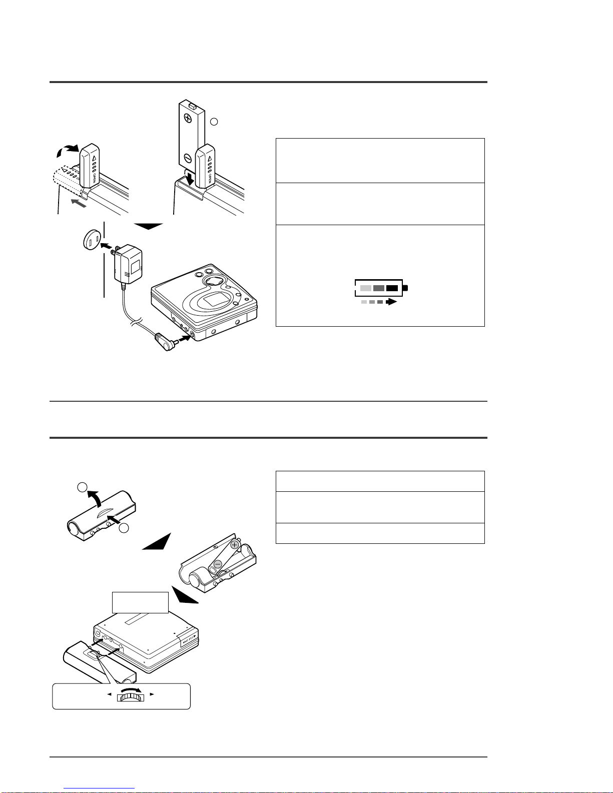
Check that the unit is connected to the stereo system.
Compruebe que el aparato esté conectado al sistema estéreo.
1
Press the REC button.
Pulse el botón REC.
2
Begin playback on the stereo system connected to this portable MD.
Inicie la reproducción en el sistema estéreo conectado a este MD portátil.
3
Press the REC LEVEL 55
55
5or 44
44
4button
to adjust the recording level.
Adjustthe recording levelso that themaximumsound volumefrom the source makes
the reading swing somewhere between –4 dB and 0 dB.
Pulse el botón REC LEVEL
55
55
5
o
44
44
4
para ajustar el nivel de grabación.
Ajuste el nivel de grabación de modo que el nivel máximo de volumen del sonido de la
fuente haga que la indicación oscile entre –4 dB y 0 dB.
This unit can adjust the digital recording level just the same as the analog recording.
Este aparato puede ajustar el nivel de grabación digital del mismo mode que en el caso
de la grabación analógica.
4
Press the PAUSE button on the stereo system to enter the playback pause mode.
Here you can search for the track to record.
Pulse el botón PAUSE del sistema estéreo para establecer el modo de pausa de
reproducción.
Aquí podrá buscar la pista a grabarse.
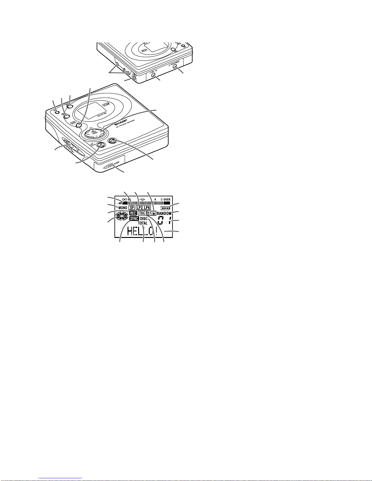
Level meter indicator
Indicador del medidor de nivel
6Press the ENTER/SYNC button.
Pulse el botón ENTER/SYNC.
7Press the MENU/CHRG button repeatedly to select recording mode.
Pulse repetidamente el botón MENU/CHRG para seleccionar el mode de grabación.
5Press the MENU/CHRG button repeatedly to select the "REC MODE".
Pulse repetidamente el botón MENU/CHRG para seleccionar "REC MODE".
8Press the ENTER/SYNC button.
The mode will be set automatically after 7 seconds even if the ENTER/SYNC
button is not pressed.
Pulse el botón ENTER/SYNC.
El mode se establecerá automáticamente después de 7 segundos aunque no se pulse el
botón ENTER/SYNC.
9Press the 0606
0606
06 button to start the MiniDisc unit recording.
Pulse el botón
0606
0606
06
para iniciar la grabación del aparato de MD.
10
Begin playback on the stereo system,and the output will be recorded.
Inicie la reproducción en el sistema estéreo, y se grabará la salida.
To stop recording
Press the :OFF/HOLD button.
When “TOC” appears, the MiniDisc
recorded contents have not yet been
updated.
Para detener la grabación
Pulse el botón :OFF/HOLD.
Mientras aparece “TOC”, aún no se habrá
actualizadoelcontenido grabadoen el MD.
To update the recorded contents
of the MiniDisc
Press the :OFF/HOLDbutton when
in the stop mode.
The power turns off after recorded
contents have been updated on the
MiniDisc.
Para actualizar el contenido
grabado del MD
Pulse el botón :OFF/HOLD mientras
esté en el modo de parada.
La alimentación se desconectará
después de haber actualizado el
contenido grabado en el MD.
TOC display
Visualización
TOC
■■
■
■
Playback /
Reproducción
1Insert the earphones plug into the PHONES jack.
Inserte la clavija de los auriculares en la toma PHONES.
2Insert a MiniDisc.
Inserte un MD.
3Press the 0606
0606
06 button.
Playback starts automatically with a playback only MiniDisc or a MiniDisc
which is protected against accidental erasure (Auto-play function).
Pulse el botón
0606
0606
06
.
La reproducción empezará automáticamente con un MD de sólo reproducción o un
MD que está protegido contra borrado accidental (Función de reproducción
automática).
To stop playback
Press the :OFF/HOLD button.
If the unit is not operated for at least 2
minutes when in the stop mode, the
power will shut off automatically.
To the PHONES jack
A la toma PHONES
Right
channel
Canal
derecho
Left
channel
Canal
izquierdo
Para detener la reproducción
Pulse el botón :OFF/HOLD.
Si el aparato no se utiliza durante un
mínimo de 2 minutos en el modo de
parada,laalimentación sedesconectará
automáticamente.
■■

– 9 –
MD-MT180
DISASSEMBLY
Cares before disassembling
When assembling the machine after disassembling or
repair, observe the following requirements so as to ensure
safety and performance.
1.Removethebatteriesfromthemachine,andtakeoutthe
mini-disc.
2. When assembling after repair, be sure to position the
wires in the same location.
Use the specified screws to fix the cabinet and the
mechanismunit. Theuseof thescrewswith lengthother
than specified may cause contact with the mechanism
unit resulting in malfunction.
3.Whenrepairing,paycloseattentionsonottodamagethe
IC from static electricity.
Caution:
Carefullyhandlethe main PWBand flexible PWB. Afterremoving the
flexiblePWB(*)fortheopticalpickupfromtheconnector,donottouch
directly the front end of flexible PWB with your hand so as to prevent
damage of optical pickup by static electricity.
(B1) x2
ø1.4 x2.5mm
(C1) x1
ø1.4 x2.5mm
(C1) x1
ø1.4 x2.5mm
(C1) x1
ø1.4 x2mm
(B2) x2
(C2) x1
*(C2) x1
Top Cabinet
EJECT SWITCH
Main PWB
Hook
(C3) x3
Pull
PullPullPull
Be careful not to break the EJECT
SWITCH when remove and attach
the bottom cabinet.
(D1) x1
ø1.4 x1.5mm
(D1) x1
ø1.4 x1.5mm Bracket
Mechanism Unit
1 Bottom Cabinet 1. Screw .....................(A1) x5 9-1
2. Open the Battery Door.
3. Hook .......................(A2) x1
2 Top Cabinet 1. Open the Top cabinet. 9-1
2. Screw .....................(B1) x2 9-2
3. Flexible PWB..........(B2) x2
3 Main PWB 1. Screw .................... (C1) x3 9-2
2. Flexible PWB......... (C2) x2
3. Hook ...................... (C3) x3
4 Mechanism Unit 1. Screw .................... (D1) x2 9-3
REMOVAL PROCEDURE
STEP FIGURE
Figure 9-1
Figure 9-2
Figure 9-3
(A1) x2
ø1.4 x4mm
(A1) x1
ø1.4 x4mm
(A1) x1
ø1.4 x2.5mm
(A1) x1
ø1.4 x2.5mm
Battery Door
Battery Terminal
Bottom Cabinet
Top Cabinet
Open Lever
1
2
Hook
(A2) x1
Pull

– 10 –
MD-MT180
REMOVING AND REINSTALLING THE MAIN PARTS
Removethemechanismaccordingtothedisassemblingmeth-
ods 1 to 4. (See Page 9.)
Howtoremovethemagnetichead(SeeFig.10-1.)
1. Remove the solder joints (A1) x 2 of the head flexible plate.
2. Remove the screws (A2) x 2 pcs. of the magnetic head.
Note:
Mount carefully so as not to damage the magnetic head.
How to remove the sled motor (See Fig. 10-3.)
1.Remove thestopwasher (C1)x1 pc.,andremove thedrive
gear (C2) x 1 pc.
2. Remove the solder joints (C3) x 3 of flexible PWB.
3. Remove the screws (C4) x 2 pcs., and remove the sled
motor and the left bracket.
4. Remove the screw (C5) x 1 pc., and remove the right
bracket.
Note:
Take care so that the motor gear is not damaged.
(If the gear is damaged, noise is caused.)
Howtoremove the spindlemotor(SeeFig. 10-2.)
1. Remove the solder joints (B1) x 4 of flexible PWB.
2. Remove the screws (B2) x 3 pcs., and remove the spindle
motor.
MD Mechanism
Spindle
Motor Solder Joints
(B1)x4
(B2) x3
ø1.4 x3mm
MD Mechanism
Solder Joints
(C3)x3
(C4) x2
ø1.4 x1.5mm
(C5) x1
ø1.7 x3.5mm
Stop Washer
(C1)x1
Drive Gear
(C2)x1
Right
Bracket
Left
Bracket
Cartridge Holder
Sled Motor
(A2) x2
ø1.4 x1.8mm
MD Mechanism
Magnetic Head
Solder Joints
(A1)x2
Figure 10-1
Figure 10-2
Figure 10-3

– 11 –
MD-MT180
How to reinstall the optical pickup
(See Fig. 11-2.)
1. Remove the screw (E1) x 1 pc., and remove the spring.
2. Slowly raise the optical pickup.
How to remove the Lift motor (See Fig. 11-1.)
1.Remove the solder joints (D1)x2 of the lift motorleadwire.
2. Remove the screw (D2) x 1 pc., and remove the lift motor.
Note:
Take care so that the motor gear is not damaged.
(If the gear is damaged, noise is caused.)
(D2) x1
ø1.4 x5mm
Lift Motor
SolderJoints
(D1)x2
Spring
Optical Pickup Unit (E1) x1
ø1.7 x3.5mm
Figure 11-1
Figure 11-2

MD-MT180
– 12 –
Entering the TEST mode
1. Setting at port (power nonconnected state)
(1) Set the port as follows.
TEST1 : "Low" (TP416)
TEST0 : "High"
(2) Turn the Power ON.
(3) Test Mode START [ T E S T _ ]
2. Setting by special button operation (in standby state)
(1) Holding down the MENU button and ENTER button, press the PLAY button.
(2) Normal mode setting initialization (BASS setting, VOL setting, etc.)
*Since the unit is changed to the setting for production line inspection , be sure to set it to the default setting state in the following default
setting procedure before returning it to the user.
(3) Test Mode START [ T E S T _ ]
(4) When the VOL.+button is pressed, indication of microcomputer version for one second [ Y 1 2 A c X ]
(5) When the VOL.–button is pressed, whole LCD lighting for 2 seconds
1 High reflection disc MMD-110 (TEAC Test MD) 88GMMD-110
2 Low reflection disc MMD-212 (TEAC Test MD) 74-minute disc 88GMMD-212
3 Low reflection disc MMD-213A (TEAC Test MD) 80-minute disc 88GMMD-213A
4 Low reflection disc Recording minidisc UDSKM0001AFZZ
ADJUSTMENT
Test disc
MD adjustment needs two types of disc, namely recording disc (low reflection disc) and playback-only disc (high
reflection disc).
Type Test disc Parts No.
Note: Use the low reflection disc on which music has been recorded.
Test Mode
1. AUTO 1 Mode • Perform preliminary automatic adjustment.
• If the combination of mechanism and pickup
PWB has been changed, be sure to start from
AUTO1.
2. AUTO 2 Mode
• Perform ATT (attenuator) automatic adjustment.
• Perform continuous playback (error rate display,
jump test)
3. TEST-PLAY Mode
• Continuous playback from the specified address
is performed.
• 1 line, 10 lines or 384 lines manual jump is
performed.
• C1 error rate display (pit section), ADIP error
rate display (groove section)
• The temperature correction is performed only when
servo start is performed, but the posture correction
is not performed during continuous playback.
4. TEST-REC Mode
• Continuous record from the specified address
is performed.
• Change of record laser output(servo gain is also
changed according to laser output).
• The temperature correction is performed only
when servo start is performed, but the posture
correction is not performed during continuous
recording.
5. MANUAL 1 Mode
• Temperature is displayed. (Updating in real time)
• Seeing the displayed adjustment value, perform
preliminary manual adjustment.
(Error rate indication, jump test)
6. MANUAL 2 Mode
• Temperature is displayed. (Updating in real time)
• Seeing the displayed adjustment value perform
manfully the preliminary adjustment.
(Error rate indication, jump test)
• Continuous playback is performed
(Error rate display, jump test).
7. RESULT 1 Mode
• The value adjusted in AUTO1 or MANUAL1 is
indicated.
• (Execution in servo "OFF" state").
8. RESULT 2 Mode
• The value adjusted in AUTO 2 or MANUAL 2 is
indicated.
• Adjustment value is changed manually.
(Error rate display, jump test).
9. DIGITAL INPUT Mode
• Digital input information is displayed.
10. ERROR INFORMATION
• Error information is displayed.
Mode • Error information is initialized
11. NORMAL Mode
• The mode is changed from the TEST mode to
the normal mode without adjustment.
• In the normal mode the internal operation mode,
memory capacity, etc. areindicated.
• In the normal mode both temperature correction
and posture correction are perfomed.
12. EEPROM Mode
• Factors of digital servo are changed manually.
(Each servo is turned on individually.)
• Cut-off frequency of BASS1, BASS2 and BASS3
is selected manually.
• Temperature detection terminal voltage is
measured, and the reference value is set.
• Defaults are selected and set.
• Setting of EEPROM protect area is updated.
(In case of protect releasing)
13.AUTO J Mode
•
AUTO 1/2, focus balance adjustment, TEST-
PLAY (ADIP/C1 error check), EEPROM are
updated sequentially.
EEPROM version
Destination
Microcomputer version
Leaving the TEST mode
(1) Press the STOP button in the TEST mode stop state.
Shipping setting method
Holding down simultaneously the VOLUME –Button and PLAY Button of the set unit without disc, supply the power from the DC IN plug.
After the indication "INIT" -> "BYE OK" disappears, release the power supply of DC IN.

MD-MT180
– 13 –
• Whenever the MENU button is pressed in the continuous
playback mode, the indication changes as follows.
* Pre-mastered disc
Continuous playback (SUBQ address indication)
[ S Q ]
Continuous playback (C1 error indication)
[ C E ]
Continuous playback (SUBQ address indication)
[ S Q ]
* Recordabl disc
Continuous playback (ADIP address indication)
[ A P ]
Continuous playback (C1 error indication)
[ C E ]
Continuous playback (ADIP error indication)
[ A E ]
Continuous playback (ADIP address indication)
[ A P ]
4. TEST-REC Mode
• When the STOP button is pressed while the TEST-REC
menu appears, or in the TEST-REC mode or continuous
record mode, the mode changes to the TEST mode stop
state.
•
When the PLAY button is pressed while the TEST-REC
menu appears, the continuous record is initiated from the
current pickup position.
• Whenever the MENU button is pressed in the TEST-REC
menu, the target address changes as follows.
0032 →03C0 →0700 →08A0 →0950 →0032 →........
When the PLAY
button is pressed while a target
address is displayed, continuous playback is performed
after searching that address.
• Whenever the ENTER button is pressed in the TEST-REC
mode target address is displayed, the digit which is
changed by the FAST FORWARD/FAST REVERSE /
button changes as follows.
0032 →0032 →0032 →0320 →........
• When the FAST FORWARD button Is pressed in the
TEST-REC mode target address is displayed, the digit of
address specified by the BASS button is set to +1h.
(0 to F)
• When the FAST REVERSE button is pressed in the
TEST-REC mode target address is displayed, the digit of
address specified by the BASS button is set to -1h.(0 to F)
*
When the FAST FORWARD/FAST REVERSE /
button is held down, the setting changes continuously,
one cycle being 100 ms.
Operation in each TEST mode
1. AUTO1 Mode
•WhentheSTOP button is pressed while the AUTO1 menu
appearsor during automatic adjustment, the mode changes
to the TEST mode stop state. At this time the adjustment
value is not output.
• Be sure to adjust, using the specified disc MMD-213A or
MMD-212.
Atthis timereleasethe EEPROM(IC402)protection. (Refer
to EEPROM write procedure.)
• Adjustment NG; Adjustment item out of range, focus ON
failure, and adjustment error
• When the PLAY button is pressed while ADJ. OK is
displayed, AUTO2 is executed.
2. AUTO2 Mode
•WhentheSTOP button is pressed while the AUTO2 menu
appearsor during automatic adjustment, the mode changes
to the TEST mode stop state. At this time the adjustment
value is not output.
• Adjustment NG; Adjustment item out of range, and adjust-
ment error.
• When the PLAY button is pressed while ADJ. OK is
displayed, TEST_PLAY is executed.
3. TEST-PLAY Mode
• When the STOP button is pressed while the TEST-PLAY
menu appears, or in TEST-PLAY or continuous playback
mode, the mode changes to the TEST mode stop state.
• When the PLAY button is pressed while the TEST-PLAY
menu appears, continuous playback is initiated from the
current pickup position.
• Whenever the MENU button is pressed in the TEST-PLAY
menu, the target address changes as follows.
0032 →03C0 →0700 →08A0 →0950 →0032 →........
When the PLAY button is pressed while a target address
isdisplayed,continuousplaybackisperformedaftersearch-
ing that address.
• Each time the ENTER button is pressed while the TEST-
PLAY mode target address is displayed, the digit which is
changedbypressingtheFASTFORWARD/FASTREVERSE
/ button is changed as follows.
0032 →0032 →0032 →0032 →........
• When the FAST FORWARD button is pressed in the
TEST-PLAY mode target address is displayed, the digit of
addressspecifiedbytheENTERbutton isset to+1h.(0toF)
• When the FAST REVERSE button is pressed in the
TEST-PLAY mode target address is displayed, the digit of
addressspecified by the ENTER buttonisset to -1h. (0 toF)
*
When the FAST FORWARD/FAST REVERSE /
button is held down, the setting changes continuously, one
cycle being 100 ms.
• When the BASS button is pressed in the continuous play-
back mode, the number of jump lines changes as follows.
1 →10 →384 →1 →........
* Afterthenumber of jumplinesis indicated foronesecond,
the address indication is restored [ T R _ ]
• When the FAST FORWARD button is pressed in the
continuous playback mode, the specified number of lines
is jumped in the FWD direction.
• When the FAST REVERSE button is pressed in the
continuous playback mode, the specified number of lines
is jumped in the REV direction.
* When the FAST FORWARD/FAST REVERSE
/
button is held down, jump is repeated every
approx. 100 ms.

MD-MT180
– 14 –
5. NORMAL Mode
• When the STOP button is pressed while the NORMAL
menu appears, the mode changes to the TEST mode stop
state.
• Indication during operation
Indication of memory capacity on main unit LCD
[ ] + Level meter
: Internal mode
: Address (Cluster section)
: Address (Sector section)
• Selection of sound volume, BASS, etc. is possible (without
indication)
• Recording is also possible.
• If the STOP button is pressed during operation in the
NORMAL mode, the NORMAL mode is canceled, and the
power is turned off.
6. Error data display Mode
• Reversing when FAST REVERSE button is pressed
• When the STOP button is pressed while the error data
indication menu appears or during error data indication, the
mode changes to the TEST mode stop state.
• Error data 0 is the latest error.
• Error which occurred in the TEST mode is also stored in the
memory.
• When the MENU button is pressed while the error data
indication menu appears, the error data is initialized.
[ C L E A R _ ]
• : Error Code
Explanation of error history code
13h :
Excessive number of retry to draw servo during its
adjustment.
16h : COUT detection time over during servo adjustment.
17h : The level of input signal from the RF amplifier is out of
the allowable range.
1Fh :Cannot clear the factor of ENDEC DINT.
21h : Cannot focus on the disc.
22h : Cannot start up the spindle.
23h : Track search time over.
32h : Cannot read P-TOC.
42h : Cannot read U-TOC.
44h : Cannot write U-TOC.
45h : Cannot perform write test of U-TOC.
52h : Cannot write SD. (Sound Data)
71h : Time over during initialization of the pickup position.
72h : Check sum error occurred when reading EEPROM.
73h :
Cannot operate the recording head (by using the EJECT
lever).
91h :
The ambient temperature is out of the allowable range.
7. Auto J Mode
•AUTO1/2,focusbalanceadjustment,TEST-PLAY(ADIP/C1
error check), EEPROM are updated sequentially.
• If the STOP button is pressed while processed, the same
operation as the normal STOP button operation will be
performed.

MD-MT180
– 15 –
EEPROM (IC402) writing procedure
1. Procedure to replace EEPROM and write initial
value of microcomputer in EEPROM
(1) Replace EEPROM.
(2) Refer to the latest EEPROM data list.
(3) Press the MENU button, ENTER button and Play
button to start the test mode.
(4) Press the VOL.+button, version display
[ V e r . ]
EEPROM version (c ~ z)
MicrocomputerROMversion
(5) Press the VOL.–button, the whole LCD lights.
(6) Test mode stop state.
[ T E S T ]
(7) Pressthe"BASS"button,andpress3timesthe"FAST
REVERSE " button.
[ E E P R O M ]
(8) Performtheoperationtodisplay"EEPROMSETTING
ENTER CHART", compare the EEPROM DATA LIST
with the display, and set according to the EEPROM
DATA LIST with the VOL.+or VOL.–button.
(9) Set the temperature reference. (Refer to the Tem-
perature Reference Setting Method.)
(10)
Set according to the EEPROM DATA LIST.
(11)
Press the Stop button.
[ T E S T ]
(12)
Press the Stop button.
(13)
After data is written in EEPROM, turn off power .
(14)
Restore protection of EEPROM.
2. Temperature reference setting method
[1] Measurement, calculation and setting procedure
(1) Set the TEST mode.
• Set TEST 1, 0 = '01', and turn on power
(or set PLAY ON in standby state).
(2) Press the MENU button, ENTER button and Play
button to start the test mode.
(3) Start the EEPROM mode 'Temp' menu.
• ButtonoperationinorderofBASS,FASTREVERSE
x 3 times, PLAY , PLAY in the test mode
STOP state.
• 'TM§§ ' is displayed. (§§= Temperature code,
= Temperature reference)
(4) Once press FAST FORWARD , and determine
the displayed microcomputer TEMP input AD value.
• 'TPin##' is displayed. (## = TEMP input AD value)
(5) At the ambient temperature, determine the tempera-
ture corrected value from the temperature measure-
ment value correction table.
(6) Determine the temperature reference, using the fol-
lowing formula.
• Temperature reference = Microcomputer TEMP
input AD value + Temperature corrected value
(7) Set the temperature reference value by button opera-
tion, and check whether the temperature code indica-
tion corresponds to "Temperature Code Identification
Table".
[2] Temperature measurement value correction table
[3] Temperature code identification
X
Ambient
temperature Temperature
correction Center
temperature
– 9oC ~ +10oC 08h + 0.5oC
+ 3oC ~ +21oC 07h + 12.5oC
+15oC ~ +33oC 06h + 23.6oC
+26oC ~ +43oC 05h + 35.0oC
Ambient
temperature Temperature
correction
+ 9oC ~ +11oC - 05h + 10.0oC
+12oC ~ +14oC - 04h + 12.7oC
+15oC ~ +16oC - 03h + 15.4oC
+17oC ~ +19oC - 02h + 18.2oC
+20oC ~ +22oC - 01h + 20.9oC
+23oC ~ +24oC±00h + 23.6oC
+25oC ~ +27oC + 01h + 26.3oC
+28oC ~ +30oC + 02h + 29.0oC
+31oC ~ +33oC + 03h + 31.8oC
Center
temperature

MD-MT180
– 16 –
C T 0 _ 0 2 H
C T 1 _ 0 1 H
C T 2 _ 3 2 H
C T 3 _ 5 0 H
T S A _ 2 0 H
U S A _ 1 8 H
P L E _ A 0 H
R C E _ 9 4 H
S D F _ 1 F H
F B 0 _ F C H
B H S _ 0 0 H
B S 0 _ 1 7 H
B S 1 _ 7 0 H
B U 0 _ 0 1 H
B D 0 _ 0 5 H
B D 1 _ D C H
B M K _ 1 E H
B E C _ 0 0 H
C S T _ 6 9 H
I J U _ 8 1 H
I J D _ 5 5 H
M C T _ A 1 H
E R C _ 5 A H
C V 0 _ 1 6 H
C V 1 _ 1 0 H
S S K _ B 9 H
A C T _ 6 3 H
C 1 E _ 5 2 H
A D E _ 0 0 H
F G 2 _ 7 0 H
T G 2 _ 2 A H
M F P _ ◊◊H
S P M _ ◊◊H
M S L _ ◊◊H
U S 0 _ ◊◊H
U S 1 _ ◊◊H
U S 2 _ ◊◊H
EEPROM DATA LIST (EEPROM version c)
TEMP setting
Item display Set values
T M _ _ Calculate values
Tracking setting
Item display Set values
T G 1 _ 1 4 H
T B o _ 2 0 H
T B t _ 1 2 H
T K o _ 2 0 H
T K t _ 0 D H
T D o _ 6 7 H
T D t _ 3 4 H
S C t _ 3 A H
C L p _ 2 4 H
C L r _ 3 0 H
J P I _ 0 E H
K 1 0 _ 6 5 H
T H P _ 0 2 H
T H G _ 0 2 H
T O P _ 0 0 H
T O G _ F 2 H
T 1 P _ 2 0 H
Spindle setting
Focus setting
F G 1 _ 4 0 H
F Z H _ E D H
F L n _ 0 9 H
F L p _ 0 6 H
F T s _ 1 8 H
F S B _ 4 0 H
F T B _ 2 8 H
T O 1 _ 5 0 H
T O R _ 5 8 H
Item display Set values
S P G _ 3 0 H
S P i _ 9 A H
S P m _ 6 2 H
S P o _ 4 F H
S D 1 _ 7 F H
S D 2 _ 7 F H
S P K _ E B H
S P W _ 0 F H
S P B _ 6 6 H
S R i _ C 0 H
S R m _ 9 A H
S R o _ 7 B H
S B R _ 6 0 H
O S L _ 1 4 H
P J G _ 4 6 H
Item display Set values
Sled setting
S K S _ 7 F H
S K L _ 7 F H
S L C _ 2 4 H
S T L _ 0 7 H
S T M _ 4 2 H
S T E _ A 6 H
S D V _ 6 0 H
S J P _ 0 3 H
W T m _ 1 8 H
S R V _ 5 4 H
S L T _ 5 C H
M V S _ 0 A H
S L S _ 2 8 H
Item display Set values
Sled setting (Continued)
Item display Set values
S K E _ 0 E H
S D E _ 1 C H
B P E _ 7 1 H
B P W _ 7 5 H
B P 1 _ 3 3 H
B R E _ 9 5 H
B R W _ 3 3 H
S R S _ 3 C H
ADJ. SET setting
Item display Set values
C O K _ 2 8 H
F A B _ 6 4 H
H S G _ 1 1 H
L S G _ 1 2 H
Bass setting Item display Set values
B 1 A _ 0 0 H
B 2 A _ 0 0 H
B 3 A _ 0 0 H
Control setting
Item display Set values
◊◊H : CHECK-SUM

MD-MT180
– 17 –
: Test Mode STOP
: Auto 1 & 2, Focus balance adjustment menu
: Pre-auto adjustment menu
: ATT auto adjustment menu
: Continuous record menu
: EEPROM setting menu
BASS
T E S T
Slide external
periphery move Slide internal
periphery move
Test Mode Menu
Test Mode Change Chart
A U T O J
A U T O 1
FAST FORWARD FAST REVERSE
FAST REVERSE
FAST FORWARD FAST REVERSE
T R E C
FAST FORWARD FAST REVERSE
: Continuous playback menu
T P L A Y
FAST FORWARD FAST REVERSE
: Digital input signal monitor menu
D i n M o n
FAST FORWARD FAST REVERSE
FAST FORWARD
FAST FORWARD
FAST REVERSE
FAST REVERSE
FAST FORWARD
* When the [STOP ] button is pressed in specific menu, the "TEST MODE STOP" state is set.
* When the [PLAY ] button operation is performed in the specific menu, the operation of this
menu is executed.
: Pre-adjustment value check menu
R S L T 1
: ATT adjustment value check menu
R S L T 2
: Pre-manual adjustment menu
M A N U 1
: ATT manual adjustment menu
M A N U 2
: Error history display menu
E D A T A
: Test mode normal playback menu
N O R M A L
E E P R O M
A U T O 2
: Preautomatic Adjustment menu
: Preadjustment error (adjustment value output)
: During preadjustment adjustment
Adjustment error
Normal end
: Preadjustment normal end (adjustment value output)
: During ATT automatic adjustment
PLAY
PLAY
A U T O 1
Preautomatic Adjustment
A D J . O K
A D J . N G
A T 2
A T 1
* When the [STOP ] button is pressed in specific menu, the "TEST MODE STOP" state is set.
* " " represent the adjustment number as follows.
0 0 : Innermost periphery move
0 2 : ABEF offset tentative measurement
0 4 : RF side focus gain coarse adjustment
0 5 : Focus ATT tentative setting
0 6 : RF side bit section tracking gain adjustment
0 7 : COUT level setting for pit section adjustment
0 8 : External periphery move
0 9 : RF side groove section tracking gain adjustment
1 0 : COUT level setting for groove section adjustment
1 1 : RF side TCRS gain adjustment
1 2 : Tracking ATT initial setting
1 3 : RF side focus gain minor adjustment
1 4 : Focus ATT initial setting
1 5 : S gain "High" ABEF offset measurement
1 6 : TCRS offset measurement
1 7 : S gain "Low" ABEF offset measurement

MD-MT180
– 18 –
: ATT auto adjustment menu
: ATT adjustment error (adjustment value output)
: During ATT auto adjustment
Adjustment error
Normal end
: ATT adjustment normal end (adjustment value output)
: Continuous playback (high reflection)
: Continuous playback (low reflection)
PLAY
ENTER
A U T O 2
ATT Auto Adjustment
A D J . O K
A D J . N G
S Q # # # #
A P # # # #
A T 2
* When the [STOP ] button is pressed in specific menu, the "TEST MODE STOP" state is set.
* " " represent the adjustment number as follows.
0 0 : Innermost periphery move
0 3 : Pit section tracking ATT setting
0 4 : Pit section focus ATT setting
0 6 : External periphery move (low reflection only)
0 7 : TCRS ATT setting (low reflection only)
0 8 : Groove section tracking ATT setting (low reflection only)
0 9 : Groove section focus ATT setting (low reflection only)
: Focus balance Adjustment mode
: Focus balance
# # # : Jitter error
PLAY
b # # #
: Continuous playback menu
: Continuous playback (pit section)
: Continuous playback (groove section)
# # # # : Address
: Continuous playback (pit section)
: Continuous playback (groove section)
# # # # : Address
PLAY
T P L A Y
Continuous Playback
S Q # # # #
A P # # # #
* When the [STOP ] button is pressed in specific menu, the "TEST MODE STOP" state is set.
* In the start address set state the start address changes as follows when the [MENU] button is pressed.
0 0 3 2 H(initial value) 0 3 C 0 H0 7 0 0 H0 8 A 0 H
A d 0 0 3 2 A d 0 3 C 0 A d 0 7 0 0
MENU
MENU
MENUMENU
A d 0 8 A 0
* In the start address setting state the start address change digit changes when the [ENTER] button is pressed.
1st digit (initial value) 2nd digit 3rd digit
A d 0 0 3 2 A d 0 0 3 2
ENTER ENTER
ENTER
A d 0 0 3 2
* In the continuous playback state the number of jump lines changes as follows shown
the [BASS] button is pressed.
1 (initial value) 10 384
1 T R 1 0 T R
BASS
BASS
3 8 4 T R
BASS
• Continuous playback from current pickup position
: Continuous playback menu
: Start address setting
MENU
T P L A Y
A d 0 0 3 2
PLAY
S Q # # # #
A P # # # #
• Continuous playback from any address
* In the start address set state the value of selection digit changes in the range of "0h to Fh"
when the [FAST FORWARD/REVERSE / ] button is pressed.
* When the [FAST FORWARD ] button is pressed in the continued playback mode, jump of specified
number of lines occurs in the external periphery direction.
If the key is held down jump occurs continuously (100 ms cycle).
* When the [FAST REVERSE ] button is pressed in the continuous playback mode, jump of
specified number of lines occurs in the internal periphery direction.
If the key is held down, jump occurs continuously (100 ms cycle).
A d 0 9 5 0 H
0 9 5 0 H

MD-MT180
– 19 –
: Continuous record menu
PLAY
T R E C
Continuous Rrecord
A P # # # #
* When the [STOP ] button is pressed in specific menu, the "TEST MODE STOP" state is set.
* In the start address set state the start address changes as follows when the [MENU] button is pressed.
• Continuous record from the current pickup position
: Continuous record menu
: Start address setting
: Continuous record
# # # #: Address
: Continuous record
# # # #: Address
PLAY
T R E C
A d 0 0 3 2
PLAY
A P # # # #
• Continuous record playback from any address
A d 0 0 3 2
0 0 3 2 H(initial value) 0 3 C 0 H0 7 0 0 H0 8 A 0 H
A d 0 3 c 0 A d 0 7 0 0
MENU
MENU
MENUMENU
A d 0 8 A 0
* In the start address setting state the start address change digit changes when the [ENTER] button is pressed.
A d 0 0 3 2
1st digit (initial value) 2nd digit 3rd digit
A d 0 0 3 2 A d 0 0 3 2
ENTER
ENTER
ENTER
A d 0 9 5 0
: TEST mode normal playback menu
: Continuous playback
@@@@@@: Mode and address display
PLAY
N O R M A L
Test Mode Normal Playback
@@@@@@
* When the [STOP ] button is pressed in specific menu, the "TEST MODE STOP" state is set.
* When the NORMAL mode is canceled, the power is turned off.

MD-MT180
– 20 –
: EEPROM setting menu
: Focus setting menu
: Spin setting menu
: Tracking setting menu
: Sled setting menu
: BASS setting menu
: TEMP setting menu
: Adjustment setting menu
: LSI setting menu
: Control setting menu
PLAY
E E P R O M
EEPROM Setting
F o c u s
S p i n
FAST FORWARD FAST REVERSE
T r a c k
FAST FORWARD FAST REVERSE
S l e d
FAST FORWARD FAST REVERSE
B a s s
FAST FORWARD FAST REVERSE
T e m p
FAST FORWARD FAST REVERSE
A D J S E T
FAST FORWARD FAST REVERSE
L S I _I F
C T R L
FAST FORWARD FAST REVERSE
FAST FORWARD
FAST REVERSE
* When the [STOP ] button is pressed in specific menu, the "TEST MODE STOP" state is set.
* When the [PLAY ] button operation is performed in the specific state, the specific setting menu is set.
: Error history display menu
: Error history 0 display
§ § : Error code
: Error history 1 display
§ § : Error code
: Error history 2 display
§ § : Error code
: Error history 3 display
§ § : Error code
: Error history 4 display
§ § : Error code
: Error history 5 display
§ § : Error code
: Error history 6 display
§ § : Error code
: Error history 7 display
§ § : Error code
: Error history 8 display
§ § : Error code
: Error history 9 display
§ § : Error code
PLAY
E D A T A
Error History Display
E 0 § §
E 1 § §
: Error history display menu
: Error history clear
MENU
E D A T A
C L E A R
FAST FORWARD FAST REVERSE
E 2 § §
FAST FORWARD FAST REVERSE
E 3 § §
FAST FORWARD FAST REVERSE
E 4 § §
FAST FORWARD FAST REVERSE
E 5 § §
FAST FORWARD FAST REVERSE
E 6 § §
FAST FORWARD FAST REVERSE
E 7 § §
FAST FORWARD FAST REVERSE
E 8 § §
FAST FORWARD FAST REVERSE
E 9 § §
FAST FORWARD FAST REVERSE
RC :
FAST FORWARD FAST REVERSE
• Error history clear
• Error history display
* When the [STOP ] button is pressed in specific menu, the "TEST MODE STOP" state is set.
: Total Recording Time
This manual suits for next models
1
Table of contents
Other Sharp CD Player manuals

Sharp
Sharp QT-CD80H Quick start guide

Sharp
Sharp MD-MT831H Quick start guide

Sharp
Sharp MD-S321H User manual

Sharp
Sharp MD-MT866H User manual

Sharp
Sharp MD-MS722H User manual

Sharp
Sharp MD-MT770 User manual

Sharp
Sharp MD-MT90W User manual

Sharp
Sharp CD-BK147V User manual

Sharp
Sharp MD-MT45H User manual

Sharp
Sharp MD-MT877 User manual

Sharp
Sharp MD-MS702MK User manual

Sharp
Sharp MD-MS721H User manual

Sharp
Sharp QT-CH88H User manual

Sharp
Sharp MD-MS701H User manual

Sharp
Sharp MD-MS701H(BL)2 User manual

Sharp
Sharp MD-MT18H User manual

Sharp
Sharp MD-MT877H User manual

Sharp
Sharp MD-MS722 User manual

Sharp
Sharp MD-MT821 User manual

Sharp
Sharp QT-CD170H User manual